Note: Descriptions are shown in the official language in which they were submitted.
P ~
- - s:6~4~ , 2 0 7 7 0 1 1
.; r~ ' MnnTTT.SiR MPnTrA~ T.~.T~ YS~rPM
~ I ,
- ~, I ...
~s
., ' ~ "'-~ .,
~ -Trr"'lTTND OF TTTP T~VFN~IrN
Fiel 1 of ~hn Inventlon
- ~ This invention pert_ins to ~ ' light systeTI for u6e in
hospiti~ls and heAlth 1~ 11t~n, Ihe llght syste~ includes An
~, .. ~.
~ ~ 1nA~1An light, ~n _rlbient light, ~ reGdinq light, Gnd G night
._ s ~ llght And is prQ~er~bly nounted in-the celllng,.
=: s~
. .
~ :' '~. Descrlntlon cr th.- Prior Art
~= , ~ ,
~ -'~ In hospitals Gnd siT~llGr heG~h cr T~edlcal ~A~-.11~t1~s~ lt iY
. ~ desiri~ble to provldo thc bedridde~ patient with four types of
lights -- the first i5 an Anbie~t light Which provldes
,~" : ..... :
-' ~' - bn~.}~iL~ , preferi~bly rcrlected, llght to _ lArge GreA
surrounding the bed; the second is ~ reAdlng light whirh provide~
- - direct llght to A portlon of the piYtlent's bed: thQ tblrd ls Gn
' r.;
- . ~ ~; cY~T~ln_tlon llght whlch dlrects G hi~h lntenslty llght to
lhC~An~1Ally the entlre GreG of ~the p~tlent~s bed: ~nd the
-~ fourth ls G night llght which hGs ~ ield GdjustGbly directed to
~, ~ eith~r the right or the le~t slde of the pGtlenT is bed. The
ss ~s Grblent light typloGlly hG~ Gn 1 l l llsss~1 nA1~1 rm V_lUQ of
_pproxln_t~ly 50 foot-cGndles while the re~dlng llght typiCGlly
-- hGs Gn ~ lrl~ ni~t 1 nr~ VGlUe or G~. a, 1 y ~O foot--cGndles Gnd
. ~ ~ ~.: the ~ n,l~ 1 sn light typiCGlly hG8 Gn ~ l l nllt~ rm VGlUQ of
G~I~L~h_Lrly 100 foot-cGndlQs. The night light typiCGlly hGs Gn
;~ ~ 111~1rl1n:~t1rsn value Or .rrrr~v1r~t~1y 30 to 40 foot-cGndles Gt G
" ' ''.2
; ~ 7 clipbo~rd--sized slreG (typicGlly G circul~r ~reG Gbout twQlvQ to
:~- Qighteen inches in diaT~teter) Gbout three to four fQet fror. tho
:- ; groun~ on the side o~ thQ patient's!.bed.
' ~i' .:. ~
".'' ' 'B
h -_,
'' f ' ' ' ' ', . .. .
: 5
~ ~ ' .. 2~770:~1
~, 'L: L ~
- ~ Ad~itionally, $t i5 desir~ble to provide A rer~ding light in
--~- uhich the p~tlent ~nd visitors ~re not exposed to rwny gl~re from
- I the fixture rQgardless of whethe~ the pntient is lying ~lat,
' sitting up in A re~ding positiol~, or reclining on the bed in Any
posltion in between the flat or ~.eading position.
Moreover, it is desir~ble to provido an ambient light
ww Wherein nn indirect light is bounced ~ron the wall to provide
4' ~-' light ~ppropriate for the patient tQ relax, w~toh television, or
'i,:7 ~ receive visitor~.
= ~ Similarly, it io desir~ble ta provide an ex~=in~tion li~ht
in ~ down-light module th~t ~ocuses light c~lh~ n~1~11y within
-- - ' the length of the bed ~or ~`'.~n.ti~`.l of the p~tient by the
medic~l staff. It is further de~ir~ble to provide such ~ light
within n module which c~n be used iidividu~lly or repe~ted as
m~ny times as necessary to 2~chieve thQ level of light ~ppropri~t-
~, for the type of c~re being given. When more th~n one module is
-. 'i. ~ .,.
~: ~ ~~ used, the modules could be switché~ se~r~tely-to provide
~; ~ dif~erent intensities o~ lignt. ~
-- Moreover, it is desir~ble to provide ~ nurso's night light
which focuses ~ n~rrow light to either side of the piltient's bea
~; 80 that a nurse is able rend t medicnl ch~rt, ~ clipboard or
-~*^ similar writing while at~nding beside the bed without ~ llrhin
T~ ~ ~ the sleeping piltient.
In the prior ~rt, these lights were typic~lly providea
- ~ ~ individually in a h~lph~zard way. ~)ifferent types of l~mps i~nd
~ - light fixtures were placed ~round the bed with numerous plugs
- competing with Dedic~l equipnent for ~v~ ble outlet sp~ce.
5Ç Moreover, such an wa8 unsightly ~nd could impede the
mobility of the patient, the p~tient's bed, or the S~lrro~-nr~in~
v -- medicnl .~- i .
a~ Wall-mounted fixtures allevi~tQd some of the nbove-
~ .
.! , . . . ,~'
7--.' '
,'
r ' ~' . ~_
7all
;f;P.I 5~fi^i~ P~I but Gtill lert much to be desired
l y and, more import~ntly, oould impede ~ccess to th-
'.. t
patient, and were e~sily d~naged by motor driven _ed l._a.ll,~.aL.I~.
dditionally, in tho prior ~Ft, medic~l light~ have not been
provided withln moduleG so th~t iirferent combinations o
'-7 ~A.~ re~ding, ~mbient, examin~tion and night lights could be
= ~? ~-
.`' ;~- in. ~L~ e.L~ into ~ single fixture.
~j ,^,p~TARCT~ ~ MMARV OF ~IIR IIlVRN'rTON
- 7 ~' It is therefore ~n objeot ot this invention to provide a
~i modular mediclll lighting ~y-~tem with ~ re~ding light module, ~n
. V, '~ ' ' ambient light module, lmd ~n ex~mination light module.
~- It is thererore 1~ rurther ob~ect Or this invention to
:7~ provide a modular modio~l lightinq ~ystem wherein the reading
. - liqht modulQ, the ambient light m_dule and the ox~min~tion light
~ ,.: , .
module o~m be combined within ~ lzod light rixture,
usod individu~llly, or combined i~to- p~irs.
It is thererore a rurthor o~oot Or this invontion to
provide a modul~r medical llghtlng ~ystem whoroln the roading
~. ~ :,~ light does not oxpo~e the p~tiont cr visitors to glr.r~ rog~rdlo~s
-- ~ Or whether the pationt i8 lying fl~t, ~ltting up in ~I ro~ding
position, or roolining on tho bed in zny ~osition in betweon the
k= rl-lt or reading position. . -
- 7~ ~ It is thorororo ^ still further. object oi; thi~ invention to
"~ ~ provide ~ modul~r medic~l lighting system includlng ~n amhient
.; light whorein ~n indirect light.is bounc-d from tho wall to
provide light ~ppropri~to for ~ho F~Pn~ to Fel~xr wAtch
television, or recoive visitors. .
. ~:
- ~: It is therororo ~ still rurthor ob~ ect Or this invontion to
.. . .
provide a modular De~ic~l lighting.~ system including zm
; . ,: ' ,
: ~ 3
.. ~,. ...
. ;;
Ji.; : . .
..
: s '~
6 ' , ,,, i . .
2~77~11
inn light in a down-llght uodule th~t focu~es light
h~tAn~A11y withln the length of the bed for ~ n~nr o~ the'
patient by tho redio~l stcf f .
'~ ' It is therefore a still further ob~ect of this invention to
/ - ~' ~ provide a modul2r medical lighting systeo wherein the examinztion
=~ light is provided within a rlodu}ë; which c~n be used individu~lly,
or repented ~s m~ny tlmes ~9 necess~ry to v~ry the level of
l ight . ;'
It is therefore a fin~l object o~ this inventlon to provide
`-~ '~ a modular medio~l lighting sy~te~: inoluding ~ night light th~t
~ ' focusec light to the side of tho l~ed cO that c nurse c~n read a
-, ~ ,' olipboard or medic~l ch~rts witho~'t d~ rh1n~ the patient.
These and other objeots ~re efectively attained by
providing ~ oeili~,,J m~Ju..~ nedio~} lighting system which
' includes four individunl d~d1r~t-.d r,odular light ~ixtures.
' '~ Preferably, one of eaoh of tl~e fbur rodules are oorbined to form
,~ '' ~ ~ a lighting fixture which is designëd to be plcced so that one o~
-- the shorter ends of the reotangïe ls plcced ~ ct~n~1A11y on the
5 ,~ ceiling-wall interf~ce directly over the hend o~ the pntient's
~, bed. ~ho bed is plcced so thnt the'~onger sides of th~ bed ~r~
parallel to the longer sides of t,he ror~-llns~ r light fixture.
' ~ ~ - ~, ' However, the modules c~n be used indiv~du~lly or corbined into
' ~ ~ ~` p~irs to provide c liDited number ~r the above-;d~n~ f~
- ~ .. s~ funotions.
~ ''= ;~ A first modul~r light fixture inoludes n fluorescent bulb
- ~nd a reflector designed to direct Iight tow~rd the rorw~rd
portion of the pntient ' 9 bed 80 ~8 to cllow a patient to read
' ~ comfortably. A second modular light flxture includes a
fluorescent bulb and a reflector cnsigned to direot light tow~rd
vertio~l w~ll cbutting the he~d'Of the p~tient'- bed 80 ns to
-- provide a reflected light over ~ ge s~rea ~round the p~tient's
"
'' ~ 4
:.,,. ~
,
h ~
~ , ~0770~ ~
,. - , . .
. bed. A third modul~r light fixtllre includes two to four
Fl l-~r sronl- bulbs which are orlented r~rron~ ~ r~ rly to the bcd.
- ~ The fluorescent bulbs hnve ~ ligbt distribution pnttern which is
;~? ~ e~.h~n~ lly oriented in the direction perp n~iirllAr to the
bulb. Therefore, the entire Are~i of thQ bed ls P~;ri~ntly
~-: ill n71t d providing an -~n~l~inn light. A ~ourth Dodular
- dS; light fixture includes ~ h~riinn~l~l h~logen bulb oriented ~bove
the ~mbient light fixture. A mirror reflects the light from th~
h~logen bulb downwardly. The po$ition or the mirror c~n be
d~usted to direct the light to thé ~,eft or right side of the
bed .
~ The fluorescent bulbs in the re~ding, ~mbient ~nd
- ~ ~. exnm~n~tion modul-s ~re prefemblX binx~ or other U-sh~ped bulbs.
The bulh in the night light module is prefenlbly ~ 120 volt,
~r medium base, narrow spot, 50-55 watt h~logen reflector ll~mp.
,.s ~ ''. '
` -=, ~ R~ .
? ~, .. ..
~"_'. '' ~' .
.. ..
. ~, , ~ ..
. .-'- ' .
,,. . ~, :-
. ~ ' 7
, . .,y., ~ . ,
*'
: ~ . '
~. " -? .
"'~' ~- ` .
~.. .:
~ !~ . '.
237~
' . . . .
p~TRF Ur.~~ 1 1 ~N OF l~TIF. rl~lrT~r-c
~s~ ~ Further objects and a.lv~ Or the invention will become
w*:
pp~lrent fron the following description ~nd clains, ~nd fron the
lng dr~wings, whcrein:
~~ Figure 1 is ~ sid- pl~m view; partly in cross section, o~
- ~- the nodular medical light system 0r tho present invention.
- ~ ~ Pigure 2 is ~ bottom plan view o~ the modul~r medical light
- ~ - ~ syste3 o~ the present invention ~ylth the shields ~round the
; :. ~ .
~s ~ F;gure 1 is a ide p1;n View, partl in cross section, o~
Y
the modular medical light system showing the ~rez~ of ;ll~min~tinn
of the re~ding light nodule.
~; ~ Figure 4 is a side plan view, p~rtly in cross section, o~
the re~ding llght module o~ the nodular nedical liqht syste=.
_ ~ Figure 5 i8 r side pl~n view, p~rtly in cross section, of
~; the modular nedical lighting system showing the ~rea of
., ~
~, ;11 in~t~n of the ~mbient light module.
Figure 5~ is ~ ~ront plnn view, p~rtly in cross section, o~
the nodulur nedic~l lighting systen showing the Are~ o~
~ ,s~ , .
~, ~w-w ill 'n~t;r~n of the night light notlule.
~,.:
~ ' Z~ Figure 6 is ~ side pl~n view;:p~rtly in cross section, o~
the ambient light nodule of the modul~r medical li ht 5 stem.
= ~ g Y
-- ~- Figure 7 is ~ side pl~n view; p~rtly in cross section, cr
'k-
-~ ~ the modular medic~1 lighting syst~rm. showing the aren or
. illumin~tion of the p~tient .. '~ n light nodule.
_ Figure 8 is ~ side pl~n view, p~rtly in cross seQtion, of
- ~ the p~tient ex~min~tion light modu1e o~ the nodul~r medio~l light
~ system. -.
- ~, Figure g is a sidQ pl~n view, p~rtly in cross section, ot
the re~lding light nodule and the ~ ' ' ~n light nodule.
s Figure 10 iB ~ Bide plim view' partly in cross section, cf
~'',
T
_ '~
. ~ ' ".
. . `' .
~~ i 20~70~1
the re~ding light modulo and the; lDatient oxamination light
rlodulo, with ~ ~lank modulo or an extondod pationt ~Tr-~n~nn
light module ~shown ln ph-mtoI) t~._L. ~ _ '
Figure 11 is ~I side pl~n viei- partly ln cros~ soction, Or
the ro~ding light module ~nd tho ~mbient light module (lncluding
~, ~ a night light nodule) of the modular medic~l light system.
.. ~ Figure 12 is ~ side plun view, plrtly in cross section, of
. , ~ ~,.,; .
g~ the ~r;oient light modul~ ~nd the patient ~T~m~ nn light module
Or the modular medical light systom:
Figure 11 is ~ side pl~n viet~i; pa~tly in cross ~iection, Or
^~ the night 1 ight module of the Dodular medic~l light systor
~a~
.1 . .
,. .
, ~ :
. ,',
'
,
-, ' ' ' ~
'' ~ '
;` 7
':
~' ' ;.
2~?~
nF~l~ATT~t~n U~ ~rlU~ o~ pRr~ ?~Fn !~
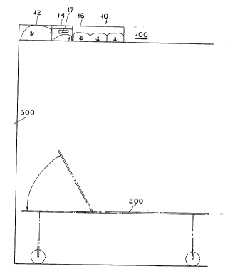
Rererring now to the drawings in detail wherein like
- ~ nuDerAls indic~te like ~leDents Li~:o~yllu~lL the sever~l view3,
Figure 1 is ~ side pl~n view, p~rtiy in cross section, of the
Dodular medical lighting system 10 o~ the present invention while
Figure 2 is Z! bottom pl~n view of modular medic~l lighting ~iyste=
10. Modular medic~-l lighting ~ystem lo i8 mounted in ceiling
;~ ~- 100, directly over ~ p4tient's bed 200, and preferAbly ~d~cent
; to wall 300. Pre~erably, ~odular Dedic~l liyhting is four feet
- long and two feet wide to conforD; to st~ndard lighting rixture
sizes .
~ odular Dedic~l lighting systeD 10, in its coDpletQ ~nd
preferred r~hor~;-^.^n~ includes rQ~ding light module 12, nDbient
- j ~ light DOdUle 14, rY~dn~inn light Dodule 16, ~nd night light
module 17 tover ambient light module 1.4~ . ~s di~closed in commonly
~, owne~ U.S.P~tent No.5,086,375,i~nued ~eb.4,1994, the re~ding light
module 12, the ~Dbient light Dodule 14, ~nd the ex~Dinition light
. Dodule 16 (and by in~erenoQ, night light Dodule 17~ D~y be
;nl ~7r~t~d into ~ single light ri~cture. However, these Dodules
~'~,~ ~_r, ~. Day also be provided sep~r~tely and placed within a hoUsing.
- ~ ~ lloreover, as shown in Figures 9-12, less than ~11 rour modules
m~y be pl~ced within the housing :~or ~ limited nuDber or
runctions to be provided.
Figure 3 shows the light distribut~on pattern o~ re~ding
light Dodule 12 in rel~tion to .the Jp~tient reposing upon bed 200.
As the light is directed ~t ~n ~Ltgi~ ~way ~roD wnll 300, the
light is not directed into the patient's eyes, re~J~.r~llr of
~ whether the position o~ the head o~ bed 200 is in ~ ~ully
-~6 reclining or p~rti~lly ~lev~ted ti.e.. ~ "sitting up" position).
8iDil~rly, ~8 the light ~lel r;h~tt;f~n pnttern of reading light
;~ ' '
~ 8 ~
.~ - '' .
- $
.'~'. ~ ~ ,""''.
,,~ . . . . .
'`j'f f '' .' . '' ' ' ' ,' ' ' '
':" ' ' ' .
207~011
module 12 is limited by non-refLective bnrrier 20, visitors und
other people etanding proxinatQ to bed 200 Are not exposed to
~= glare ~rom reading light nodul~ i2.
~" ., :
Figure 4 show~ reading light nodulQ 12 in more detail.
Reading light module 12 inolude~ hou6ing 13 which contuins
reflector 22. boUsing 13 is typically supported by a grid or
inverted T-rails 101. Additione~ly, housing 13 may be supported
by a frame or housing 98 ~8 shown in Figure3 10 und 11 and i'rume
or housing 98 supported by the grid of inverted T-rails 101.
Reflector 22 ~s highly æpecular a~d ~ n~1Ally ellipsoidul in
shupe with an ~xis 24 inclined 80 ~s to direct the light
distribution p~ttern nt an Angle away from ~djucent wall 300. U-
shaped bulb 26, prefer-lbly a bi~X~ cr similar bulb, is placed
with the centers of both legs 28, 30, ;n~ C~ct 1ng inclined ~xis
24 so that the light is directed principally nway from wall 300.
Seni-circular shield 32 is placed: around the lower leg 30 of U-
sh~ped bulb 26. Edge 34 of shie~d 32 is al$gned with the lower
edge 38 of non-re~lective b~rrier 20, as ~ t~t~d by line 400,
to prevent uncontrolled direct em~n~til~n or glare from bulb 26.
-.3,' ' .
~ ~ Edge 36 of shield 32 is sinilarly aligned with the lower ~dge 40
,, - of refleotor 22. As will be di~cus~ed with regard to Figure 13,
bl~rrier 20 mAy inolude an aperture through which light rrom night
. ~ - light module 17 is directed to a nirror oriented so as to direct
; - the light rrom night light nodule 17 to a side o~ bed 200.
Figure s shows the light ~1c'-rih~ n pattern of anbient
- light nodule 14 in relQtion to bed.200 ~Ind ad~acent wall 300.
The light is ~11F~r~hllt~ Ally evenly along ad~aoent wall
; . 300, pre~erably stopping short of the lowest portions o~ wall
~: 300, 80 that the light cun diffuse or "wash" fro~ wall 300
thereby providing indirect ~Imbie~t light to bed 200 and the
~UrroUnding area w$thout enanating ;Qny substantlQl glar~ to the
!' -~
i,i -`~:',
:, .
.:, '; - ' ` . . ,
;~
; 2~)7701~
p~tient or persons 6t~nd$ng in the iDD~di~te ~rQ~.
Figure Sa shows a view ~roD the head of bed 200 showing the
light distribution pattern- of night llght Dodulo 17 to either thc
lert or the right o~ bed 200.
Figure 6 shows aDblent light Dodule 14 in Dore detail.
Ambient light Dodule 14 includes housing 15 which contains highly
specul~r polished re~lectcr 46 . ADbient light Dodule 14 i3 typi-
cally supported by a grid of lnYerted T-rails lol. Additionally,
housing 15 may be supported by a ~ De or housing 98 Z~8 shown in
Figures 11 nnd 12 and ~r~De or hou3ing 98 supported by the grid
o~ inverted T-rails. !lighly specular polished reflector 46 i~
formed above and rearwardly ~roD inclined U-shaped bulb 48
(pre~er~bly a biax or siDilar buibj. The ~orward edgn 51 Or
..
reflector 46 joins forward vertic~l w~ll 50 which, in turn, ~oins
lower horizontal wall 52. Thc inberior of both vertioal wall 50
and horizontal wall 52 are prerer~bly highly re~lective whitQ
glossy enamel to eliminate hot spots ~nd striping o~ the
reflected light on wall 300 Elorizo tal wall 52 shields th
. n O
patient froD light directly ~roD bulb 48. SiDilarly, thQ
rearward edge 54 o~ hnr~nn~l wal~ 52 include3 upw~rdly
extending lip 56 to 3hield the p~tient from re~lected 1~DP
image3.
The position ~nd In~-lln~ 1nn of U-shaped bulb 48 provide
.
; - direct light on the uppermost PoFtiOn Or wall 300 wheroas the
~; In~rm~ t~3 portion of wall 300 i8 ~11 'n~t~d by light
' S
reflected ~roD reflector 46. As previously stated, prererably
the lowest portlon Or wall 300 i3 njot 111 n~I~5 by aDbient
ligh DO e 14
Figure 13 siDilarly disclo3es the aDbient light Dodule 14,
~md additionally disclo3e~ th~ night 1ight DOdUle 17 upwardly
~ adj~cent to aDbient light Dodule ii, liight light Dodule 17
: . , :.,.
: . ~
:,, ~ . ,: . . .
. .. -~ .
.,' . .
207701 1
:
includes horizontally oriented hplogen bulb 110 within channel
112. Channel 112 extends ~hr~ht~ tperturQ 114 [shown in ph_nton~
and into reading light module 12 t~here the light ~rom bulb llo
strike3 pecul tr Anodized ~tlunintn mirror 116. Nirror 116 is
oriented to dlrect the light dow w~trdiy. Addition~lly, mirror
116 i5 rot~tt~tble ~tbout ~t lnr~;t~t;r-l ~IXi8 of fixturo 10 50 ~ts to
allow the selection of the dlrection oi' the llght to be on elther
the lert or right sldo Or the bed 200 ~ts shown in Flgure ~a.
Plgure 7 shows thQ llght ~;~t1^ih~tt;m~ ptttern of ov~m;nAt ;nn
light module lG in relation to bed ioo ~tnd ~td~tcent w~tll 300.
FY~m;n~t~nn light module 16 prefe`rably includes three substan-
tially identicAl opticAl systems 60, 62, 64, but n~ty include Ony
nunber, includlng one, o~ optlcal systems. A plurAllty cf
optlcal systens ~tllcws the ;ll~m;r_~;nn intensity Or exanin~ttion
light nodule 16 to be vnried ~ts appropriate for the c~tre being
administered to the p~ttient.
Figure 8 shows the ex~tmin~ttion light module 16 in more
detall. ~ nAt;nn llght nodule 16 1ncludes housing 66
enclosing optlc~l systems 60, 62,: 64. FY~m;n~;n~t llght =odule
16 is typically supported by ~t gr1d Or inverted T-r~til- 101.
Addition~tlly, housing 66 m~ty be sLpported by a rrane or housing
98 And ~r~tme or housing 98 supported by the grid o~ inverted T-
rAils as shown in Figures 10 ~tnd ii. _~Ach optical systen 60, 62,
64 includes highly polished specu~:~r r-flector 67 with two
l l y ~ Al contours 68 70 ~orning ~tp~x 72
,~ . . . .
.. ~,j Ul_L~' U-shAped bulb 74, prererably ~t biAx or sinil~r
~ ~ - bulb, is p~c;t;nn~rl below Apex 72 t~th first leg 76 inmedicttely
over second leg 78. 8emi-circul~tr shietld 80 is rnc;~ under
ç second leg 78 with flrst ~tnd second edges 82, 84 vertically
~; Aligned wlth a central pcsiticn between rirst leg ~6 and second
leg 78 50 as c-~l~c~Ant ;:-l ly to elimi;ttA'çe the direct unreflected
i~ ' ~'' 11'''
,'~, ~ ' , .
,:,~ ,, ,
.:
''i' ~' :
: ' :
:~ ~ . 207~0~ 1
And uncontrolled emanation of llght from nntinn light modulo
r :, 16. Outward ends of -11 ir~ir~l qontours 68, 70 join vertical
-~ - non-reflective (preferably black)~rlsers 86, 8~.
~llipsoidal contours 68, 70 are rn~itinnor with respect to
-- bulb 74 so that the ~lrst foc~l point of both contour~ 68, 70
lntersect at point go i ; At~iy above first lcg 76 . The second
focal points 92, 94 of ~ll ircoidr~ contours 68, 70 occur immedi-
- ately below the lower edges 96, 9? of varticAl non-rerlective
risers 86, 88. Moreover, bulb 74 ~nd ~ll;rcnirl~l contours 68, 70
~re con~lgured to dlrect a beam within the ~ngular limits
., ~ .
generally of the p~tient's bed 200 as shown ln Figure 7.
Figure 9 discloses how a re~dirlg light =odule 12 ~nd ~
,~- p~tient ~n~tinn light module i6 c~n be separ~tely mounted to
' ",f ~ provide their respective reatures~.
Figure 10 discloses ~ re~ding light module 12 ~-nd a patient
examination light module 16 mounted o* framo or housing 98 wlth
blank module 99 or ~ddition~l rtic~ systems (shown in phantorl)
o~ min~tinn light module 16 betpeen =odules 12 And 16.
8imil~rly, Figure 11 dlsclQses ~ re~ding light modulo 12 ~nd
--= an ~Imbient light module 14 (~long ~ith night llght module 17) ln
~rame or houslng 98 and Flgure 12 ~4iscloscs an amblent llght
~- module 14 and ~n 'n~t;n~ ilght module 16 ln rr~me or housln~
98. Addltlonally, any of mod~lles i2, 14, 16 or 17 (17 typic~lly
~~ belng ln~ .,L~.. elLed ln 14) c-~n be provlded ~s ~ sep~rate fixture
for their respcctive ~
- Re~dlng llght modul~t 12 typlc~lly h~s ~n illu=lnation v~llue
- of ~pproxim~tely 70 foot-c~mdles while ambient light module 14
:~ typically has an ~ mlr~t;nn value of elU~L~Al~L~ly so foot-
c~ndles and ex~min~tion llght _odu~,e i6 typic~lly h~s ~n
I ~ ~11 'n/~t~r~n value of ~pproxim~taIy 100 foot-clmdles. Night
~ ~ llght module 17 typically has An il'l 'n-t~on v~lue cr 30 rcOt-
: ~ :
12
' :e
.~
-. ~s. 2~7701~
.'
' ~ ~ candles.
he nodular =edical lighting systen 10, whether prcvided
- ~ conplete system cr Assenbled frcsn individual nodules, is
:' .
recessed or surface nounted on ceiling 100. To use nodulAr
nedical lighting systen 10, the user typicAlly cperAtes An
integrAted switch nechAnism (not ,shown~ either cn wAll 300 or on
'~ ~ '~. a cord (not ~hcwn~ ~ hl e to the patient and/or nedicAl
.; ' 7'' personnel.
~s Thus the several ~.r~ oned objects And ~dv~ y-3 ArC
ncst effectively Attained. ~lthough A single preferred
ho~ 1 mPn~ of the invention hA5 b~een disclosed And described in
,* ~ detail herein, it should be, ~ nd thAt this invcntion is in
no sense linited thereby And lts ~cope is to be r~ rm1n~1 by
~: that of the appended clains.
,'', ~' ' ' .
.,,
'' " ' ,.';:
' '; ~ "
", :~... ;
, ~, ~e.
, ~ s ~*~;
4~ ' .
,S ,' : .
2,
. :
¢ ,^^ '
S ' , -"~
'h . ;. 13
.", .,~ ".
2~
. .
V X ' '
. ' I