Note: Descriptions are shown in the official language in which they were submitted.
`
I' .
Title: ALVMINUM WELDING PROCESS AND MIXTURE OF REACTANTS
FOR USE IN SUCH PROCESS
:.
I, ' 1.
TECHNICAL DISCLOSURE
This invention relates generally to the art of weld-
.ing. More particularly, the invention concerns a unique
welding process and a novel mixture of reaciants for use in
such process. SpecificaIly, the invention concerns a novel :~
,.
application of the thermite reaction to the welding of
aluminum.
.
~.
.:
'
.
BACKGROU~D OF INVENTION
The thermite reaction has been utilized for a long
. . "
period of time in order to provide weldments normally
associated with the railroad industry and in electric power
,' .
,. :
,'~
7~
.
--2--
transmission. The thermite reaction is comprised of a
reaction between aluminum ~Al) and a metal oxide wherein
the metal oxide is reduced providi~g a filler metal, i.e.,
the source of the filler metal is the oxide on reduction.
" ,
The "Goldschmidt" reaction is the basis of the application
of the process described in U.S. Patent No. 2,229,045 to
Charles A. Cadwell. This reaction is as follows:
Alu~inum ~ Iron Oxide = heat + Aluminum Oxide ~ Iron (filler metalj
. (~1) (Fe203) (A1203) (Fe)
' or
Aluminum ~ Copper Oxide = heat ~ Aluminum Oxide + Copper (filler me~al)
(Al) (CuO) (A1203) (CU)
The "Goldschmidt" reaction has been successfully
utilized over the years to weld or join metals such as iron
(Fe) and copper ~Cu). However, the process is not particu-
larly well adapted for use in jolning metals such as
aluminum ~Al) wherein the use of a copper (Cu) or iron (Fe)
'filler metal is generally unacceptable.
' U.S. Patent No. 3,020,610 to Rejdak discloses a met~od
~ welding aluminum ~Al) and other metals, and provides a
listing of varlous reactions which can be utilized to
produce reaction products which may be utilized to provide
a weldment. Unfortunately, in the method disclosed by
Rejdak the weld which is formed is not suitable for some
applications. More particularly, the weld metal formed by
the Rejdak method is not chemically pure enough for some
applications. For example, a weldment prvduced by the
Rejdak method in some environments may be susceptible to a
. .
,. :
--3--
high level of corrosion due to the presence of impurities
or unwanted elements in the resultant weldment.
U.S. Patent No. 2,569,956 to Schiltknecht discloses a
process whexein a thermite reaction is utilized to join
together a pair of non-ferrous metal pieces by melting a
sleeve about the metal pieces. This process is usually
referred to as the "Alusuisse Process" referring to a
,welding system produced by Swiss Aluminum Ltd. of Zurich.
Unfortunately, the "Alusuisse Process" is an indirect
welding process (i.e., the heat generated by the thermite
reaction does not produce a weld filler metal by chemical
reaction) and it is not suitable for use in some joining
applications.
SUMMARY OF THE INVENTION
The present invention provides a new and improved
method and means for producing molten weld metal for use in
welding or joining two or more metallic pieces or sections
which affords various distinct advantages over the prior
art. More particularly, the invention provides a direct
thermite welding process that is capahle of producing weld
metal that is substantially similar in chemical composition
to the metallic pieces being joined and is thus capable of
being used to join non-ferrous metals such as aluminum.
Additionally, the process provides for the use of a filler
metal in the mixture of reactants utilized to produce the
molten weld metal having a chemical composition substan-
.
'. ` , ' "': ' ' '
.
~ .
_4-
tially similar to that of the metallic pieces being joined.
This filler metal does not take part in the thermite
reaction and it serves to produce the resultant weld metal.
The invention thus allows for the use of coarser filler
metals (which are generally less expensive than the finer
metals required in prior art processes) and results in a
slower burning reaction that evolves fewer gases.
In general the process includes the steps of providing
a mixture of reactants comprising a reducin~ agent, a
metallic compound which is exothermically reduced by the
educing agent, and a filler metal that does not react with
the metallic compound. Upon exothermically reacting the
reducing agent and the metallic compound heat, a metal
dxide slag, evolving gases and molten weld metal are
produced.
As used herein this specification and the claims below
the term "weld metal" means the metal which is the resul~
.. .
tant product of the thermite reaction exclusive of any
slags or evolving gases produced by the reaction. The weld
metal serves to weld or hold together the metal pieces
being joined. The filler metal produces at least about
90 percent by weight of the resultant weld metal. Prefera-
bly, at least about 95 percent by weight, and more prefer-
ably at least about 97 percent by weight of the resultant
weld metal is produced by the filler metal.
At least about 90 percent by weight of the weld metal
has a chemical composition substantially similar to that of
,
': ~ ' . ~ ' ;'' :
. ,;, ~ , :
--5--
at least one of the metallic pieces being joined. Prefera-
bly, at least about 95 percent by weight, and more prefera-
bly at least about 97 percent by weight of the weld metal
has a chemical composition substantially similar to that of
at least about one of the metallic pieces being joined.
The process is particularly well suited for use with
joining two or more pieces of non-ferrous metal such as
aluminum (Al) or aluminum ~lloys. When aluminum (Al) or
aluminum alloy pieces are being joined the mixture of
~reactants may comprise from about 20 percent to about
50 percent by weight of a metal sulfate such as, for
example, magnesium sulfate (MgSO4), barium sulfate (BaSO4)
or calcium sulfate (CaSO4), from about 40 percent to about
70 percent by weight aluminum (Al), from about .1 percent
by weight to about 45 percent by weight silicon (Si), up to
about 10 percent by weight of a chloride salt such as, for
example, sodium chloride (NaCl) or calcium chloride (CaCl)
and up to 10 percent by weight of a suitable flux such as,
for example, calcium fluoride (CaF2~. Preferably, the
mixture of reactants comprises from about 30 percent by
~weight to about 45 percent by weight metal sulfate, from
about 42 percent by weight to about 60 percent by weight
aluminùm (Al), from about .2 percent by weight to about 9
percent by weight silicon (Si), from about 2 percent by
weight to about 7 percent by weight of a chloride salt and
from about 2 percent by weight to about 10 percent by
weight flux. More preferably, the mixture of reactants
.... .
. . . - . ~ , :,
.
,
comprises from about 35 percent by weight to about 42 per-
cent by weight metal sulfate, from about 45 percent by
weight to about 52 percent by weight aluminum (Al), from
about .2 percent by weight to about 9 percent by weight
silicon ~Si), from about 4 percent by weight to about 5
percent by weight of a chloride salt and from about 5 per-
cent by weight to about 7 percent by weight flux.
The foregoing and other features of the invention are
hereinafter more fully described and particularly pointed
out in the claims. The following descriptions setting
forth in detail certain illustrative embodiments of the
invention, these being indicative, however, of but a few of
- the various ways in which the principles of the invention
may be employed.
BRIEF DESCRIPTION OF DRAWING
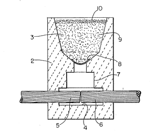
Figure 1 is a cross-sectional view of a welding
apparatus suitable for use in the present invention.
DETAILED DESCRIPTION
, In accordance with this invention it has been found
that a plurality of filler metals may be utilized via the
thermite reaction to produce weldments but without having
the filler metals actually enter into the reaction. Thus,
in accordance with this invention, a filler metal for use
in a weldment is provided into a mixture with a metallic
clompound which is exothermically reduced by the reducing
.. ..
:
~ ?~g~ ,3~
agent to produce heat to melt the filler metal which then
flows from the reactant and product mixture as weld metal
to provide a weldment. Other product components are left
behind in a slag with reaction gases released. The process
,is generally summarized as follows:
Reducing + filler + metallic = heat + weld + slag + gases
agent metal compound metal
In accordance with this invention it has been found
'with the above reaction that the reducing agent may be
selected from the group consisting of aluminum (Al),
magnesium (Mg), zirconium (Zr) and equivalent metals which
exhibit compounds which have a high thermodynamic heat of
formation with respect to the reaction product between the
metal and the metallic compound to be reduced. For exam-
ple, aluminum (Al) can reduce a metal oxide or sulfate'
forming aluminum oxide (Al2O3) which exhibits a heat of
1, ,
formation of 399 kcal/mole at 25- Celsius. Such a reaction
is highly exothermic providing sufficient heat to raise the
temperature of the filler metal beyond its melting point so
that the molten filler metal can be directed into a weld
'cavity, i.e., the mold, to affect the weld and join two or
more metallic pieces or sections.
The metallic compound may general,ly be selected from
the ~roup consisting of magnesium sulfate (MgSO4), calcium
sulfate ~CaSO4), and barium sulfat~, (BaSO4), fluoride
compounds, and equivalent materials which upon reduction
' contribute one or more elements to exothermically form a
: . .
., :~.. . .
--8--
compound with the reducing agent. Preferably, the metallic
aompound is utilized in an anhydrous form and preferably
all of the reactants are protected from moisture prior to
use. Moisture contamination may suppress the exothermic
reaction.
The reaction between aluminum (Al) and metal compounds
containing oxygen, such as oxides and sulfates, is particu-
larly useful because of the high amount of heat liberated
when aluminum oxide (A1~03) is formed. However, other
exothermic reactions may be employed such as the one
between ma~nesium (Mg) and polytetrafluoroethylene ~C2F4)n,
forming magnesium fluoride (MgF2) and providing heat to melt
the filler metal. Magnesium fluoride (MgF2) exhibits a heat
of formation of 264 kcal/mole at 25- Celsius. The metallic
compounds used in this invention generally do not, on
reduction via reaction with the reducing agent, provide for
a metallic phase which serves as the filler metal or
.. . . .
becomes a part o~ the resultant weld metal. In fact, the
metallic compounds of the present invention upon reduction
via reaction with the reducing agent usually form minerals
associated with the slag or oxide residual. This is in
contrast to the method disclosed in Cadwell U.S. Patent
No. 2,229,045 wherein the metallic compound (i.e., iron
oxide (Fe203)) provides a metallic phase on reduction to
become the filler metal or resultant weld metal (i.e., iron
(Fe)~.
I'
,
.' :
~ q~'7.~
The filler metal of the present invention may be any
metal which is desired to be utilized in a welding process.
Because of their use in electric transmission applications,
aluminum (Al) and copper (Cu) are particularly useful as
filler metals to weld aluminum (Al) or copper (Cu) articles
" ~ i
respectively. In the case of aluminum (Al) welds wherein
one or more sections of aluminum (Al) are being joined, the
filler metal and the reducing agent are both aluminum (A13.
Whereas, in the case of copper (Cu) welds where one or more
101 sections of copper (Cu) are being joined, mixtures or
alloys of copper (Cu) and aluminum (Al) can be used to
provide for the reduction process and to provide for the
filler metal. Additional filler metals may be selected
from the group consisting of iron ~Fe), iron alloys, non-
ferrous metals and alloys, solders and brazing filler
metals or others where the heat from the exothermic reac~
~tion is sufficient to raise the temperature of the filler
metal beyond its melting point and to provide additional
superheat to the filler metal such that it i5 useful in
producing a weld metal for joining metallic pieces.
The mixture of reactants may additionally include a
flux to lower the melting point of the mixture and prod-
ucts. Commonly utilized fluxes such as calcium fluoride
(CaF2), magnesium fluoride (MgF2), cryolite (Na3AlF6)~ and
other substances such as alkali compounds, particularly
alkali silicates and fluorosilicates, can be used to lower
the fusion point and increase the fluidity of the reaction
I . ,
~,
- 1 O-
products (i.e., "slag") such that the molten filler metal
can readily be separated from the slag and flow into the
mold cavity.
An unexpected advantage has been found with regard to
the particle sizes of reactants utilized in the process of
this invention. In the prior art of thermite welding, the
materials utilize aluminum (Al) at a particle size smaller
than 325 Mesh (i.e., less than 44 micrometers in diameter).
IThe metal oxide is normally utilized at a larger particle
size than 325 Mesh. In accordance with this invention,
when the reducing agent aluminum (Al) is employed it may be
utilized at a particle size of greater than 325 Mesh Ifor
greater than 90% of the aluminum (Al) by weight. This has
two unexpected advantages. This brings about a reaction
rate which exhibits a uniformly slow burning rate with low
gaseous emissions. A second advantage is that the coarser
aluminum (A1) is less expensive than the finer materials
normally required.
An additional unexpected advantage of this invention
I is that the filler metals can produce weld metal comprising
97% or greater of the desired element or alloy. There is
believed to be currently no direct thermite process in
existence for welding aluminum (Al) conductors providing
for this kind of purity in the weld metal. Since much of
the world's power transmission is accomplished with alumi-
num (Al) conductors, this means that the process Qf this
~invention is a more efective and efficient substitute for
..
': ,
- 1 1--
mechanical connectors which must be maintained or elimi-
nates the requirement for expensive TIG (gas tungsten-arc
welding~ or MIG (metal inert-gas welding) welding.
The process of this invention also helps to eliminate
segregation in the weld metal caused by limited solubility
of constituents such as aluminum (Al) and tin (Sn) as ~ound
in the prior art thermite process for welding aluminum (Al)
conductors. The process also helps to eliminate the
presence of elements causinq galvanic corrosion thus
providing outdoor connections for power transmission and
grounding. The process also eliminates additional steps or
equipment as required with the "Alusuisse Process" or
furnaces used in foundry welding operations.
! The process of this invention also allows for the use
of permanent steel molds when welding aluminum (Al) or its
alloys. The reactant mixtures of this invention require
, high temperatures for initiation of the reaction thus
helping to provide for safety in use.l The reactions are
slow and steady thus helping to prevent violence and the
slag materials should not present a disposal prablem.
The process of this invention is particularly well
adapted for use with the welding apparatus formed from two
graphite blocks or various other materials as shown in U.S.
Patent No. 3,020,610 to Rejdak. The entire disclosure of
the Rejdak U.S. Patent No. 3,020,610 is incorporated herein
by reference. Figure 1 is an example of a welding appara-
tus 1 which may be utilized with the present invention.
,.
, ~.
~ '
-12-
Welding apparatus 1 comprises a pair of blocks 2 which are
hollowed out to provide an upper crucible portion 3 and a
~mold cavity portion 4. Blocks 2 are releasably connected
or clamped using any one of a variety of means. Metallic
pieces, or more particularly, cable ends 5 and 6 are
clamped in the mold cavity portion 4 with their opposed
ends located substantially vertically below sprue 7 which
is closed by means of a small metal disc 8. The mixture of
` reactants 9 is then placed in the cruclble portion 3 and a
Istarting material 10 may then be placed on top of the
mixture of reactants 9. The starting material 10 may then
be ignited with a flint gun, which in turn ignites the
exothermically` reacting mixture of reactants 9 to produce
molten metal which melts through disc 8 and drops into mold
cavity portion 4 thereby contacting and joining the ends of
the cables 5 and 6. It will be appreciated that in addi-
tion to a flint gun alternative ignition means may be
employed such as an electrical ignition system as disclosed
in Amos et al. U.S. Patent No. 4,885,452. The disclosure
of the Amos et al. U.S. Patent No. 4,885,452 is incorpo-
rated herein by reference.
' Having generally described the process of this inven-
tion, the following specific Examples are given:
,.;
~: ';, ;`. '::
-13-
EXAMPLE 1
A thermite reaction per the teachings of this disclo-
sure was conducted as follows in a ceramic crucible set
over a steel mold which holds cables to be joined and
provides for a casting mold at the cable junction using the
' following thermite mixture:
ConstituentWeiqht Percent
Magnesium Sulfate (MgSO4) 38.6
Aluminum ~Al) Powder 57.6
Calcium Fluoride (CaF2)3.8
Particle Si e Distributions of Materials Used in Exam~les
MAGNESIUM SULFATE (MgSO4)
,~ . < 44 micron - 100%
ALUMINUM (Al) POWDER
+ 20 Mesh ~840 microns 100% (by wt.)
-20 + 40 Mesh 420-840 microns 5% Max
! . -40 + 50 Mesh 300-420 microns 1-10%
-50 + 80 Mesh 180-300 microns 15-30%
-80 + 140 Mesh 100-180 microns 35-50%
2~-140 + 325 Mesh 44-180 microns 25-45%
-325 Mesh < 44 microns 5~ Max
CALCIUM FLUORIDE (CaF2)
+ 50 Mesh >300 microns 2% Max ~by wt.)
-50 + 100 Mesh 150-300 microns 0-10
-100 + 140 Mesh 100-150 microns 5-20
-140 + 200 Mesh 74-100 microns 10-25
-200 + 325 Mesh 44- 74 microns 20-40%
-325 Mesh < 44 microns Balance
A weld metal nugget is subjected to chemical analysis
and the following welding metal composition was found
(weight percent):
, .
.
:: ,
:
2 ~ ~ 7
-14-
Aluminum (Al) Powder 97,2
Silicon (Si) 0.1
Magnesium (Mg) 0~2
Sulfur (S) 1.7
The weldments made by this process were further tested
by sequentially dipping them in simulated seawater (3.5%
sodium chloride (NaCl) in distilled water) followed by
drying. In a one month process, welds made by this method
~ do not exhibit signs of corrosion whereas those made per
existing technology and disclosed in Rejdak U.S. Patent,
No. 3,020,610 and containing tin (Sn) and copper (Cuj all
exhibit signs of corrosion.
EXAMPLE 2
Two pieces of 250 MCM aluminum (Al) cable (19 strand -,
diameter 0.575 in. were welded together using the process
'of Example 1.
. .
EXAMPLE 3
Two pieces of 2/0 aluminum (Al) cable ~7 strand -
,diameter 0.419 inches) were joined by the process of
Example 1 obtaining a resistance of 100 micro-ohms (note
that total resistance is greatly affected by the measuring
~technique with stranded cable and, therefore, comparative
, values are very important when a common technique has been
used.)
, ' . . ',. ',. ~ :. ~.:, :
-15-
EXAMPLE 4
Thermite reactions per the teaahings of this disclo-
sure were conducted in a graphite crucible and mold using
the following mixture to affect welds in 2/0 aluminum (Al)
cable segments:
ConstituentWeiqht Percent.
,. Calcium Sulfate ~CaSO4)35.67
Aluminum (Al) Powder57.49
Calcium Fluoride (CaF2) 6.84
Particle Size Distributions of Materials Used in ExamPles
CALCIUM SULFATE (CaSO4)
< 20 micron - 100% (by weight)
< 10 - 95%
< 5 - 63%
< 2 - 23%
< 1 - 9%
,. ,
ALUMINUM (Al) POWDER
+ 20 Mesh >840 microns100% (by wt.)
-20 + 40 Mesh 420-840 microns 5% Max
-40 ~ 50 Mesh 300-420 microns 1-10%
- -50 ~ 80 Mesh 180-300 microns 15-30
-80 + 140 Mesh 100-180 microns 35-50%
-140 + 325 Mesh 44-180 microns 25-45~
-325 Mesh < 44 microns5% Max
CALCIUM FLUORIDE (CaF2)
+ 50 Mesh >300 microns2~ Max (by w~.)
-50 + 100 Mesh 150-300 microns 0-10%
-100 ~ 140 Mesh 100-150 microns 5-20%
-140 ~ 200 Mesh 74-100 microns 10-25%
30-200 + 325 Mesh 44- 74 microns 20-40
-325 Mesh < 44 micronsBalance
'` The joined cables were tested for resistance and
'ultimate tensile strength. Duplicate welds were sectioned
: . '' '. . ~ :- :-
~' ' ~ ; ' ' :
, . : . . .
..,
~ A
-16-
to detect the presence of porosity and to evaluate fusion
of cable ends. Results were as follows:
A. Resistance and Tensile Strength
Resistance Tensile Str2ength
(micro-ohms, 12" gauge)(lb/in )
, Unsectioned Cable 139 6348
, Welded Cable 132-137 1670-2387
B. Porosity
Results ranged from no voids visible to the naked eye
to less than three voids located near the top of the
weld nugget.
C. Fusion of Cable Ends
Cable ends r including central strands, were fused to
the filler metal.
EXA~PLE 5
Thermite reactions per the teachinys of this disclo~
sure were conducted using a ceramic crucible set over a
graphite mold using the following thermite mixture to
affect welds in 2/0 aluminum (Al) cable:
Constituent Weiqht Percent
' I Barium Sul~ate tBaSO4)49.32%
; Aluminum (Al) Powder 44.46%
Calcium Fluoride (CaF2)6.22%
I .
Particle Size Distributions of Materials Used in ExamPle
BARIUM SULFATE (BaS0~)
- < 11 micron - 100% (by weight)
< 6 - 87
< 2 - 29
.
..
: ,,
..' ' ' ~: :
. ~ ,
J
- 1 7-
ALUMINUM POWDER (Al )
+ 20 Mesh >840 microns100~ (by wt.)
-20 ~ 40 Mesh 420-840 microns5% Max
-40 + 50 Mesh 300-420 microns1-10%
~-50 + 80 Mesh 180-300 microns 15-30%
: -80 + 140 Mesh 100-180 microns 35-50~
-140 + 3~5 Mesh 44-180 microns 25-45%
-325 Mesh < 44 microns5% Max
,'
CALCIUM F~UORIDE ( CaF2 )
:;
+ 50 Mesh >300 microns 2% Max (by wt.)
-50 ~ 100 Mesh150-300 microns 0-10
, ~ -100 ~ 140 Mesh 100-150 microns 5-20
-140 + 200 Mesh 74-100 microns 10-25%
-200 + 325 Mesh 44- 74 microns 20-40%
-325 Mesh < 44 microns Balance
.
Good quality welds were obtained with acceptable
~ . I
fusion of cable ends with a small amount of porosity in the
.~ weld cavity.
: , ,
. EXAMPLE 6
20, Weldments of 1/4" x 4" aluminum (Al) busbar in a
straight splice were made using the process disclosed in
Rejdak U.S. Patent No. 3,020,610, the method disclosed
above in EXAMPLE 4 and utilizing the ~ollowing formula:
. .
.-- .
,' , ' , I
'`........ . ~, . ~ ~ . .
`` ` ~' '` ' ' ~
2~1y~
' - 1 8-
Approximate Mean
ConstituentWeiqht Percent Particle Size
Calcium Sulfate 34.2 10 microns
tCaS04)
Aluminum (Al) 55.1 150 microns
Powder
Calcium Fluoride 6.6 20 microns
(CaF2)
Silicon ~Si) 4.2 150 microns
,: ,
Thus, the process o~ the present invention may be success-
fully utilized with an alloying element such as silicon
(Si) incorporated in the mixture of reactants.
I . ,
In some applications incorporating silicon into the
mixture of reactants can be highly desirable. Specifi-
cally, it has been found that the silicon provides a range
of temperatures over which the weld metal will solidify
thus allowing the molten weld metal to feed the solidifying
interface, substantially eliminating hot cracking, wetting
the pieces that are being joined and allowing gases to
escape during solidification thereby reducing porosity
especially in larger welds. Silicon also has the effect of
strengthening the weld metal.
When silicon is employed in the mixture of reactants
it has been found to be beneficial to also include a
chloride salt. The chloride salt appears to act as a
degassing agent, possibly combining with the hydrogen in
solutlon.
.
,
,. . . . .
:... , ~ ~ "
.
2~ s ~
- 1 9-
Either calcium chloride or sodium chloride can be
used. Sodium chloride is pre~erred because it is readily
available, inexpensive, is available in many different
particle size ranges, and is not hygroscopic. It is
believed that the sodium chloride breaks down in the
extreme heat of the reaction and the chlorine combines with
the hydrogen in the molten aluminum weld metal to form
minute amounts of hydrogen chloride gas, which bubbles
away.
I When silicon is utilized in the mixture of reactants
it has also been found that the particle size of the metal
sulfate is important. Specifically, it has been determined
through SEM analysis that the finer sulfate powders (less
than 3 ~m) tended to agglomerate the mixture of reactants.
When calcium sulfate of a finer particle size (average
1.4 ~m) was added to the mixture, it was seen that the
mlxture of reactants agglomerated into very fine spheroids
in the mixer, allowing the material to flow much better.
The flowability of the powder was determined to be very
important to the consistency of the welding process. When
. . Il
using a crucible and mold configuration similar to that
used in the process disclosed in Rejdak U.S. Patent No.
3,020,610, powder which does not flow in the crucible
results in inconsistent burning and "tunneling", where the
I . ,
material does not all react before the actual welding
begins. If the mixed powder does not flow well, air
pockets may be left in the crucible and this results in an
.
' '~
2~
-20-
uneven reaction of the material. This uneven reaction
results in "cold shuts", where weld metal drops/ solidi-
fies, and more metal drops over it, and also results in
poor weld metal/slag separation. It was also determined
that too much of the finer metal sulfate resultea in
reactions that were too violent and the weld metal tended
to blow out of the crucible rather than drop to make the
weld.
Additional Examples illustrating the use of silicon in
the mixture of reac~ants are set forth below. In each of
such Examples below, the particle sizes of the constituents
- " is as follows:
~ I .
' ' '. ' ' . ',' '-~: ~
.: ' ''''"'"""'' .. :.
. . .. .
,
-21-
Calcium Sulfate (CaSO4):
Type A Type B
-44 ~m 100% 99%
-20 ~m 100% 98%
-10 ~m 95% 95%
' I - 5 ~m 63% 79%
- 2 ~m 23% 60%
- 1 ~m 9~ 40%
average size (~m) 3.75-4.4 1.4
lO Aluminum (Al) Powder: Silicon (Si) -1% Iron (Fe):
-20 Mesh 100% +30 Mesh 1% max. ,
-20 +40 Mesh 95% min. -30 +40 Mesh 1% max.
-40 +50 Mesh 1-10% -40 +50 Mesh 1-10%
-50 +30 Mesh 15-30~ -50 +100 Mesh 45-75%
-80 +140 Mesh 35-50~ -100 +200 Mesh 20-45%
-140 +325 Mesh 25-45% -200 Mesh 5% max.
~325 Mesh 5~ max.
~ ' ` ,' '.
Z~?~
-22-
Calcium Fluoride (CaF2): Calcium Chloride (CaCl):
+50 Mesh 2% max. ~35 Mesh bal.
-50 +100 Mesh 10~ max. -35 ~50 Mesh 15%
-100 +140 Mesh 5-20% -50 +80 Mesh 12
-140 +200 Mesh 10-25% -80 ~100 ~esh 3%
-200 +325 Mesh 20-40~ -100 +140 Mesh 7
-325 Mesh bal. -140 +200 Mesh 7%
-200 +325 Mesh 9%
-325 Mesh 10
,Sodium Chloride (NaCl):
Type A Type B
+35 Mesh bal.1% max.
I
-35 +50 Mesh 67% 2%
-50 +80 Mesh 16% 67~
-80 +100 Mesh 1% 12%
-100 +140 Mesh 2% 15%
. . . .
, , -140 Mesh trace19%
,
EXAMPLE 7
Twenty weldments were made using the process described
in Rejdak U.S. Patent No. 3,020,610, welding two 1/4 x 4"
aluminum busbars in a straight splice with the following
formula:
.:
I' I ~.
~ .
--23--
:` Constituent Weiqht Percent
i ~Calcium sulfate (CaSO4) 34.6% - half Type A, half
Type B
Aluminum ~Al) powder 51.7~ ~ ;
.. .
Calcium ~luoride (CaF2) 5.2%
, Silicon tSi) 4.3% - (theoretically
' resulting in 12.2~ Si in the
resultant weld metal)
Sodium chloride (CaCl) 4.2~ - type A
II. ,
Six additional weldments welding two 1/4 x 4" aluminum
busbars in a straight splice were made using the process ' :~
described in Rejdak U.S. Patent No. 3,020,610 with the
following formula: `:
Constituent Weiqht Percent
Calcium sulfate (CaSO4) 35.7% - Type A
Aluminum (Al) powder 57.5
Calcium fluoride (CaF2) 6.8%
.; I' , ,
1. The average tensile load value of the twenty splices
. made above pursuant to the formula of section I was 15,040
pounds, and the sample standard deviation was 880 pounds.
The average of the six splices made pursuant to the formula
of section II was 6960 pounds and the sample standard
deviation was 2150 pounds.
,;,
~,
.
-: ~ :: :'
-24-
.
Six splices welding two 1/4 x 4" aluminum busbars into
a straight splice were also made using a prior art Rejdak
type formulation. The Rejdak type formulation resulted in
an average tensile load of 13,330 pounds and a sample
standard deviation of 1400 pounds. The details of the
Rejdak type formulation are as follows:
Constituent Weiqht Percent
Aluminum (Al) powder 42.8%
, Tin oxide (SnO2) 39.5
Copper oxide (Cu2O) 13.4%
Calcium Fluoride (CaF2) 4.3%
The particle size of the constituents is as follows:
Aluminum (Al) powder: Tin oxide (SnO2): ~-
-100 Mesh 100% 99% < 10 ~m
-100 +325 Mesh 80~ average size = 0.3 ~m
average size (~m) 19
Copper oxide (Cu2O): Calcium Fluoride (CaF2):
' ~ I-140 Mesh 100% +50 Mesh 2% max.
~ -5 +100 Mesh 10~ max.
-100 +140 Mesh 5-20%
-140 +200 Mesh 10-25%
-200 +3Z5 Mesh 20-40%
-325 Mesh bal.
,
:~,
.
.
2,r,q ,J~
EXAMPLE 8
Twenty 100 g reactions were made in a "pencil" mold
which is designed to accentuate porosity in the weld metal.
The reaction is made in an approp~iately sized crucible,,
and the molten weld metal drops into a 1/2l' diameter hole
set at a 25' angle. Ten reactions of each of ths formula-
tions from sections I and II of Example 7 were made. The
bulk density was calculated for each of the twenty pencils,
and that value was divided by the appropriate theoretical
density to obtain a value for the theoretical porosity.
The average theoretical porosity of the weld metal using
the formula from section I of Example 7 was 9.5% with a ,.
sample standard deviation of 1.0% and the reaction
appeared consistent. The average theoretical porosity of
the weld metal using the formula from section II of Example
7 was 12.1% (27% higher) with a sample standard deviation
of 1.1% and the reaction varied considerably.
,
EXAMPLE 9
Commercial 2/0 aluminum cable was welded in a straight
splice according to the process disclosed in Rejdak,U.S.
Patent No. 3,020,610 using the formulations shown in
sections I, II and III of Example 7. These welds were
tested for resistance to corrosion by exposing them to salt
spray for three months. The welds were visually examined
and tested in tension. The average strength of three welds
made using the f~rmulations of section III of Example 7,
~; :
' '
' . : ~. ,
-26-
section II of Example 7, and section I of Example 7 was 980
pounds, 1050 pounds and 1230 pounds respectively. After
three months in salt spray, the welds made using the
formulation of section III of Example 7 showed obvious
signs of corrosion at the interface between the weld and
the cable, whereas the other two (formulations of sections
I and II of Example 7) did not. The tensile strength of
welds made using the formulations of section III of Example
7, section II of Example 7 and section I of Example 7 after
three months were 820 pounds, 960 pounds and 1250 pounds
respectively A weld made using the formulation of section
III of Example 7 completely separated after six months in
salt spray.
EXAMPLE 10
Three straight splice weldments were made between
pieces of 1/4 x 4" aluminum busbar us.ing the following
composition:
Constituent Weiqht Percent
Calcium sulfate ~CaS04) 36.7~ - 75% Type A, 25
Type B
,Aluminum (Al) powder 44~5%
Calcium fluoride (CaF2) 7.4~
Silicon (Si) 8.3% (theoretically resulting
1 in 33% Si in the resultant
weld metal)
Sodium chloride (NaCl) 3.1%
,
All the bars were welded, and the average tensile
strength was 12,450 pounds. This shows that a weld can be
,.
.,
,
' ' ~
, ~ .
'r ~
-27-
made with a very high silicon content. After the welds
were pulled, each was hit with a hammer to see iE the weld
was brittle. Each deformed at the edges rather than
breaking.
I
EXAMPLE 11
Three more welds were made using the following
formula:
Constituent Weiqht Percent
Calcium sulfate (CaS04) 34.6% - 25~ Type A, 75%
Type B
Aluminum (Al) powder 43.4%
Calcium fluoride (CaF2) 6.9%
Silicon (Si) 10.0% (theoretically result-
ing in 40% Si in the resul-
tant weld metal~
Sodium chloride (NaCl) 5.0%
All the bars were welded, and the average tensile
strength was 10,860 pounds. However, the welds were
brittle and shattered when hit with a hammer.
EXAMPLE 12
Three straight-splice weldments were made between
pieces of 1/4 x 4" aluminum busbar using each of the two
following formulas:
.. . .
, .
.. . .
, , ~ , ~ ,: : .` ::.
.
:
~?',
--28--
I.
Constituent Weiaht Percent
Calcium sulfate (CaS04) 39.7% - half type A, half
Type B
Aluminum (Al) powder 49.9%
Calcium fluoride (CaF2) 6.0%
Silicon (Si) 0.9% (theoretically resulting
in 3% Si in the resultant
weld metal)
Sodium chloride (NaCl) 3.6%
II.
Constituent Weiqht Percent
Calcium sulfate (CaS04) 38.9% - half type A, half
Type B
Aluminum ~Al) powder 49.4
Calcium fluoride (CaF2) 5.8%
~Silicon (Si) 2.3% (theoretically resulting
in 8% Si in the resultant
weld metal)
Sodium chloride (~aCl) 5.0~
The welds made using the Eormulation of section I were
, tensile tested. The average tensile strength was 11,600
pounds. The average tensile strength using the formulation
of section II was 13,000 pounds. Although the formulation
of section I probably gave adequate strength, an examina-
tion of the fracture surface revealed that the bar was
incompletely welded and large gas bubbles had been trapped
in the weld. In the weld made with the formulation of
~: ,, .. ,~.. , ,:
., :
:
'"'` '~ ,
,
-29-
section II, the bubbles were substantially smaller and the
interface was completely welded. The interface is'critical
to the electrical properties of the weld.
It is thus seen that the process of this invention
provides a novel,process for producing weldments and a
novel process for the utilization of the thermite reaction
to produce weldments.
Although the invention has been shown and described
with respect to certain preferred embodiments, it is
obvious that equivalent alterations and modifications will
occur to others skilled in the art upon their reading and
understanding of this specification. The present invention
includes all such equivalent alterations and modifications,
and is limited only by the scope of the following claims.
. . .
. I ,
.
.. , . ; - . : . ::
.
:.
- , .~ : .. : -
; :: : ,: ~ :