Language selection

Search

Patent 2077303 Summary

Third-party information liability

Some of the information on this Web page has been provided by external sources. The Government of Canada is not responsible for the accuracy, reliability or currency of the information supplied by external sources. Users wishing to rely upon this information should consult directly with the source of the information. Content provided by external sources is not subject to official languages, privacy and accessibility requirements.

Claims and Abstract availability

Any discrepancies in the text and image of the Claims and Abstract are due to differing posting times. Text of the Claims and Abstract are posted:

  • At the time the application is open to public inspection;
  • At the time of issue of the patent (grant).
(12) Patent: (11) CA 2077303
(54) English Title: MOTOR AND COOLING MEANS THEREFOR
(54) French Title: MOTEUR ET MODE DE REFROIDISSEMENT DE CELUI-CI
Status: Deemed expired
Bibliographic Data
(51) International Patent Classification (IPC):
  • H02K 9/193 (2006.01)
  • F04D 13/06 (2006.01)
  • F04D 13/08 (2006.01)
  • F04D 29/58 (2006.01)
  • H02K 5/10 (2006.01)
  • H02K 5/20 (2006.01)
  • H02K 9/19 (2006.01)
(72) Inventors :
  • BRANDT, BENGT (Sweden)
(73) Owners :
  • ITT FLYGT AB (Sweden)
(71) Applicants :
(74) Agent: SMART & BIGGAR
(74) Associate agent:
(45) Issued: 1997-08-19
(22) Filed Date: 1992-09-01
(41) Open to Public Inspection: 1993-03-04
Examination requested: 1992-09-01
Availability of licence: N/A
(25) Language of filing: English

Patent Cooperation Treaty (PCT): No

(30) Application Priority Data:
Application No. Country/Territory Date
9102517-1 Sweden 1991-09-03

Abstracts

English Abstract


The stator housing of an electric motor
has its central, rotary axis offset from,
and parallel with, the longitudinal axis
of its enclosing casing. The housing and
casing define a cooling liquid chamber
therebetween which, due to the offset
axes, define the chamber of diverse
widths. A wall, of arcuate conformation,
is joined to the casing to render the
chamber of uniform width thereabout and
therealong, and to form a separate,
lateral compartment in which to confine
conduits for conducting cooling liquid
into the chamber.


French Abstract

e logement du stator d'un moteur électrique a son axe de rotation central décalé et parallèle par rapport à l'axe longitudinal de son carter. Le logement et le carter délimitent entre eux une chambre de liquide de refroidissement, ce qui, en raison des axes décalés, donne à la chambre diverses largeurs. Une paroi arquée est ajoutée au carter afin de donner à la chambre une largeur uniforme et constituer un compartiment latéral séparé dans lequel sont confinés des conduits pour acheminer le liquide de refroidissement à la chambre.

Claims

Note: Claims are shown in the official language in which they were submitted.


THE EMBODIMENTS OF THE INVENTION IN WHICH AN EXCLUSIVE
PROPERTY OR PRIVILEGE IS CLAIMED ARE DEFINED AS FOLLOWS:


1. A motor and cooling means therefor, comprising:
a water-proof electric motor;
a stator housing enclosing said motor, said housing
having a central, vertical axis;
a casing, substantially enclosing said motor and housing
therewithin, said casing having a central longitudinal axis
which is offset and parallel to said vertical axis; and
an arcuate wall segment joined to said casing and
interposed between said housing and a portion of said casing;
said housing, wall segment and casing cooperatively
define a uniform annular chamber therebetween; and
liquid pumping means for pumping liquid into said
chamber.


2. A motor and cooling means therefor, according to
claim 1, wherein;
said wall segment and said casing portion cooperatively
define a compartment therebetween; and
said liquid pumping means includes liquid conducting
means confined within said compartment for conducting cooling
liquid through said compartment.


3. A motor and cooling means therefor, according to
claim 2, wherein:
said liquid conducting means comprises at least one


- 5 -


conduit for introducing liquid into said chamber,;
and at least one conduit is included for discharging air
bubbles from said chamber.

4. A motor and cooling means therefor, according to
claim 3, wherein:
said conduits have terminations which (a) are in
penetration of said wail, and (b) open into fluid
communication with said chamber.

5. A motor and cooling means therefor, according to
said claim 4, wherein:
said annular chamber is unobstructed fully thereabout and
lengthwise thereof.


- 6 -

Description

Note: Descriptions are shown in the official language in which they were submitted.


B Brandt-8
2~7~Q3
A MCrOR AND COOLING MEANS THEREFOR

Background of the Invention
This invention pertains to submersible, electricJ~otor driven liquid pumps, and to
means for liquid-cooling of the electric motors thereof, and in particular to such
a motor and cooling means therefor which offers greatly improved motor coolant
circulation and cooling efficiency.

A common type of pump is the so-called submersible one in which the pump and theelectric motor therefor comprise a unit which is submersed in the pumped liquid.In this, the motor normally obtains its cooling directly from the surrounding,
pumped liquid. If, however, the level of the liquid decreases, so that the motor
is surrounded by air, the cooling of the motor may be insufficient. Consequently,
it is kncwn to provide an internal cooling system, for the motor, which uses thepumped liquid for the purpose. An example of such an internal cooling system isdisclosed in the Swedish patent No. 367 465.

As the pumped liquid often contains pollutants, said patent teaches the use of anarrow slot, aLL~I~ed between the impeller of the pump and the pump housing,
through which cu"~Latively clean liquid is conducted into the cooling water areabetween the pump and the motor. Ancillary vanes, formed atop the impeller, cause
the cooling water to circulate. The aforesaid slot prevents solid pollutants from
entering the aforesaid area and, consequently, diminishes the likelihood of a clogging
of cooling channels about the motor.

Further, the cited patent discloses the use of vanes, within the cooling jacket
which houses the motor, for directing the cooling liquid upwardly, along the motor,
to effect coollng of the entire motor.

~ecs~se of the developmRnt towards larger and more powerful motors, the demand for
good cooling of such has been increased. Yet, cooling therefor available by theknown means is not always adequate. This arises due to the fact that is is difficult
for the cooling liquid to reach upper portions of the motor as solid pollutants
accrete in the cooling-liquid passages. Additionally, motors are often operatedat slow speeds and, consequently, they can not effect a sufficient cooling liquid
circulation without large, energy-demanding ancillary vanes. To solve the problem

-- 1 --

20773 0 3

and provlsion enhanced, coollng llquld clrculatlon, lt has
been proposed to convey coollng llquld to the top of the
motor in separate, outwardly-arranged condults. By thls
arrangement, the coollng llquld wlll flow down, between the
stator houslng of the motor and the surroundlng coollng
~acket. The maln dlsadvantage wlth thls ls that these
external condults are expenslve and readlly sub~ect to damage
durlng rough handllng of the motor-pump.
An alternatlve solutlon, whlch has been tested, ls
to arrange the condults for the coollng llquld wlthln the
motor houslng. Then, to lnsure that the condults wlll not
dlsturb the clrcular flow about the motor stator houslng, the
latter ls provlded wlth longltudlnal rldges or recesses ln
whlch the condults are nested. Such rldges or recesses,
however, dlsturb the symmetry and requlre that the stator
houslng have conslderably thlcker and stronger wall materlal
to sustaln the pressure loadlng thereof. Tests have
establlshed that a stator houslng deslgned ln thls way demands
wall materlal three tlmes thlcker than that requlred by a
fully clrcular stator houslng, to be able to wlthstand a same,
lnternal pressure.


Summary of the Inventlon
It ls an ob~ect of thls lnventlon to set forth a
solutlon for the aforestated problem, whlch solutlon ls not
met wlth the deflclencles, noted ln the foregolng that attend
the prlor art solutlons.
Accordlng to a broad aspect, the present lnventlon


, ~ - 2 -

72432-72

~ao77~ 0 ~
-


provldes a motor and coollng means therefor, comprlslng: a
water-proof electrlc motor; a stator houslng encloslng sald
motor, sald houslng havlng a central, vertlcal axls; a caslng,
substantlally encloslng sald motor and houslng therewlthln,
sald caslng havlng a central longltudlnal axls whlch ls offset
and parallel to sald vertlcal axls; and an arcuate wall
segment ~olned to sald caslng and lnterposed between sald
houslng and a portlon of sald caslng; sald houslng, wall
segment and caslng cooperatlvely deflne a unlform annular
chamber therebetween; and llquld pumplng means for pumplng
llquld lnto sald chamber.


Brlef DescrlPtlon of the Drawlnqs
Further ob~ects of thls lnventlon, as well as the
novel features thereof, wlll become apparent by reference to
the followlng descrlptlon, taken ln con~unctlon wlth the
accompanylng flgures, ln whlch:
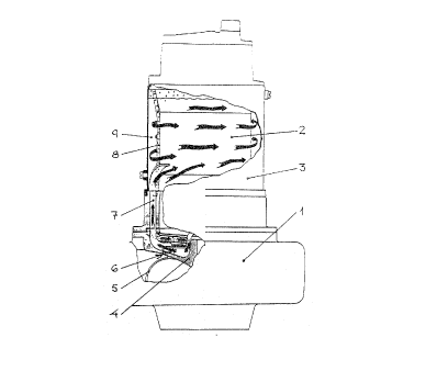
Flgure 1 ls a vertlcal deplctlon, partly cut away,
of a prlor art motor-drlven pump and coollng system therefor.


- 2a -
.-

72432-72

21~7~)3
Figure 2 is a cross-sectional view of the inventive motor and cooling
~ans therefor, according to an embodiment thereof, taken along section 2-2
of Figure S.
Figure 3 Ls a cross-sectional view of the embodiment of Figure 2, the
same taken along section 3-3 of Figure 5.
Figure 4 is a cross-sectional view of the embodiment of Figures 2 and 3, the
same taken along section 4-4 of Figure 5.
Figure 5 is a cross-sectional view of the aforesaid embodLment of the
invention, taken along section 5-5 of Figure 2.

Description of the Preferred Embodiment
The motor-driven pump and cooling system therefor, shown in Figure 1, comprises
that which is practiced in the prior art. The pump housing 1 ~ounts thereupon
a motor stator housing 2 and a casing 3. Housing 1 confines therewithin the
impeller 4 of a centrifugal pump which has main vanes 5 and ancillary vanes 6,
the latter formed atop the impeller 4. A conduit 7 conducts cooling liquid, p~mped
by vanes 6, into the casing 3 for cooling of the motor. An exhaust pipe 8 carries
air bubbles upwardly in the casing 3. The uniform spacing between the casing 3
and the housing 2 defines a annular chamber 9 through which the cooling liquid
cir~-l~tes about the housing 2.

In order to obtain an effective cooling of the motor, it is important that the
cham~er 9 be unobstructed, as protruding C~llpoll~llts would hinder an optimum flow
of the cooling liquid, and offer surfaces upon which solid pollutants could accrete.
The invention c~,~,ehe.~s the employment of con~uits for carrying the cooling
liquid well into the chamber 9 without obstructing the latter.

Figures 2 thrcugh 5 depict an embodiment of the invention in which there is provided
a compa.~ t in which to confine conduits, for cooling liquid flow, and air
bubble discharge, albeit the casing 3 is fully circular. Herein, the motor axis"Z" is offset from, and parallel with, the longitudinal axis "Z'" of the casing 3.
By this expedient, the annular chamber 9 has a given width '~r' at one side thereof,
and a greater width '~ "'at the opposite side thereof. A sheet metal wall 11, of
arcuate conformation, is coupled to the casing 3 to define, between the wall 11
and the casing 3, a separate C~"~L~ t 10. The wall 11 confonms the width at
the aforesaid opposite side of the chamber 9 to a uniformity with that of the
aforesaid one side. Consequently, fluid flow therewithin will be unifonm and

2Q~ 3
steady. Now, the compartment 10 provides a space in which to confine cooling
'quid conduits and coniuits for expelling air bubbles. As shown, then, con-
oits 7 and 7', are set within the compartment 10. The same are supplied coolingliqu1d from the ancillary vanes 6 of the impeller 4, and each has a termination
which penetrates the wall 11 and opens into fluid communication with the chamber 9.
A cooling liquid return port 12 is formed in the pump housing 1, in order that the
liquid can return to the impeller 4. The conduit 8 conducts air bubbles, which
collect in the upper portion of the casing 3, to the impeller 4.

According to the invention, the chamber 9 is wholly unobstructed, and as noted in
the foregoing, of unifonm width fully thereabout and therealong. The conduits 7and 7' efficiently carry the cooling lLquid into the chamber, and are confined
within the separately defined compartment 10. The casing 3 remains fully circular,
requiring no complicated, manufactured configuration.

While I have described my invention in connection with a specific embodiment
thereof, it is to be clearly understood that this is done only by way of exampleand not as a limitation to the scope of the invention, as set forth in the objects
thereof and in the appe,~ded claims.

Representative Drawing
A single figure which represents the drawing illustrating the invention.
Administrative Status

For a clearer understanding of the status of the application/patent presented on this page, the site Disclaimer , as well as the definitions for Patent , Administrative Status , Maintenance Fee  and Payment History  should be consulted.

Administrative Status

Title Date
Forecasted Issue Date 1997-08-19
(22) Filed 1992-09-01
Examination Requested 1992-09-01
(41) Open to Public Inspection 1993-03-04
(45) Issued 1997-08-19
Deemed Expired 2011-09-01

Abandonment History

There is no abandonment history.

Payment History

Fee Type Anniversary Year Due Date Amount Paid Paid Date
Application Fee $0.00 1992-09-01
Registration of a document - section 124 $0.00 1993-03-26
Maintenance Fee - Application - New Act 2 1994-09-01 $100.00 1994-08-15
Maintenance Fee - Application - New Act 3 1995-09-01 $100.00 1995-08-16
Maintenance Fee - Application - New Act 4 1996-09-02 $100.00 1996-08-16
Final Fee $300.00 1997-04-11
Maintenance Fee - Patent - New Act 5 1997-09-02 $150.00 1997-08-15
Maintenance Fee - Patent - New Act 6 1998-09-01 $150.00 1998-08-18
Maintenance Fee - Patent - New Act 7 1999-09-01 $150.00 1999-08-16
Maintenance Fee - Patent - New Act 8 2000-09-01 $150.00 2000-08-16
Maintenance Fee - Patent - New Act 9 2001-09-04 $150.00 2001-08-16
Maintenance Fee - Patent - New Act 10 2002-09-03 $200.00 2002-09-03
Maintenance Fee - Patent - New Act 11 2003-09-01 $200.00 2003-04-22
Maintenance Fee - Patent - New Act 12 2004-09-01 $250.00 2004-08-12
Maintenance Fee - Patent - New Act 13 2005-09-01 $250.00 2005-08-09
Maintenance Fee - Patent - New Act 14 2006-09-01 $250.00 2006-08-21
Maintenance Fee - Patent - New Act 15 2007-09-04 $450.00 2007-07-30
Maintenance Fee - Patent - New Act 16 2008-09-02 $450.00 2008-08-13
Maintenance Fee - Patent - New Act 17 2009-09-01 $650.00 2010-03-18
Owners on Record

Note: Records showing the ownership history in alphabetical order.

Current Owners on Record
ITT FLYGT AB
Past Owners on Record
BRANDT, BENGT
Past Owners that do not appear in the "Owners on Record" listing will appear in other documentation within the application.
Documents

To view selected files, please enter reCAPTCHA code :


To view images, click a link in the Document Description column. To download the documents, select one or more checkboxes in the first column and then click the "Download Selected in PDF format (Zip Archive)" or the "Download Selected as Single PDF" button.

List of published and non-published patent-specific documents on the CPD .

If you have any difficulty accessing content, you can call the Client Service Centre at 1-866-997-1936 or send them an e-mail at CIPO Client Service Centre.


Document
Description 
Date
(yyyy-mm-dd) 
Number of pages   Size of Image (KB) 
Description 1996-11-12 5 208
Description 1994-03-26 4 216
Claims 1994-03-26 2 68
Cover Page 1997-08-15 1 44
Cover Page 1994-03-26 1 23
Abstract 1994-03-26 1 19
Drawings 1994-03-26 5 177
Claims 1996-11-12 2 49
Representative Drawing 1997-08-15 1 11
PCT Correspondence 1997-04-11 1 27
Office Letter 1993-04-05 1 72
Prosecution Correspondence 1996-10-01 1 31
Prosecution Correspondence 1996-08-30 2 50
Examiner Requisition 1996-05-22 2 70
Fees 1996-08-16 1 45
Fees 1995-08-16 1 66
Fees 1994-08-15 1 46