Note: Descriptions are shown in the official language in which they were submitted.
2077333
MULTIPOSITION DETENTING HINGE APPARATUS
Field of the Invention
This invention relates generally to hinged housings
for miniature electronic equipment and more particularly
to foldable radiotelephones which utilize a detenting hinge
10 apparatus to locate the position of the folding portion.
Background of the Invention
Portable, cellular phones are increasingly utilized to
permit a user to communicate telephonically over a
wireless system at virtually any location. The portable
telephone transmits a low wattage, radio frequency signal
to a receiving station whereat connections are provided
2 0 with conventional telephone systems. Numerous receiving
stations are spaced apart at fixed locations in an area to
receive the signals transmitted by the portable telephone
as the portable telephone is relocated throughout the area.
Telephones utilizing two housing elements connected
with some type of hinging mechanism, are common in
wireline telephone sets and landline wireless extension
phones and have become more common in portable cellular
radiotelephones. This folding arrangement allows for the
telephone to be more compact when the two housings are
3 0 folded upon themselves.
Some radiotelephones which utilize this type of
design have most of the electronics within the larger of
the two housings. The smaller housing, which will be
called the flip element hereinafter, normally contains the
2 2077333
microphone and the ringing element. For good acoustical
performance, the flip element must be held in an optimum
position relative to the body of the radiotelephone. In
doing so, the microphone is positioned a desired distance
S from the user's mouth.
Other radiotelephones which utilize this type of
design have all the electronics within the larger of the
two housings. The flip element contains no electronics. A
flip element of this sort may have the capability of
10 producing an on-hook condition when the flip element is in
the "closed" position and an off-hook condition when the
flip element is rotated to its "opened" position. A
radiotelephone which employs the position of the flip
element for control purposes was described in U.S. Patent
15 No. 4,845,772. When the flip element is in its "closed"
position the radiotelephone is in a standby state ready to
receive an incoming call. The flip element covers at least
a portion of the keypad on the body of the radiotelephone
thereby shielding the keys to avoid accidental key
20 depression or contamination of the keys with foreign
material. When the flip element is in the "opened"
position, some background noise is shielded from the
microphone by the flip element.
A variety of techniques have been used to position
25 the flip element in the closed and open position. A
radiotelephone which holds the flip element in the closed
and open position using an enclosed cam element which
follows recesses in one shaft securing the hinge elements
was described in U.S. Patent No. 4,897,873. A cellular
30 telephone named "Pocket Commander" (TM) manufactured
by Fujitsu model no. F80P-171 utilizes a partially
cylindrical hinge shaft having two essentially planar
surfaces. The the plane of the each planar surface
intersects to form an acute angle. A U-shaped wire spring,
3 2077333
held in a fixed position, applies pressure to one planar
surface of the rectangular portion of the hinge shaft to
hold the flip element in its closed position. As the flip
element is rotated, the wire spring expands around the
S cylindrical surface portion of the hinge shaft until the
wire spring applies pressure to the other planar surface of
the rectangular hinge portion of the hinge shaft to hold the
flip element is then held in its open position. A cordless
radiotelephone manufactured by Panasonic model no. KX-
T3000H utilizes a helical spring having each end extended
beyond the helix forming a predetermined obtuse angle.
One end of the helical spring is attached to the flip
element. The other end of the helical spring is attached to
the body of the radiotelephone. In its closed position the
flip element is latched to the body of the radiotelephone.
When the latch is released the flip element springs away
from the body of the radiotelephone to its open position
determined by the obtuse angle formed by the ends of the
helical spring.
2 0 Such assemblies which predetermine the position of
the flip element, however, require a multiple-step process
in order to a fix the hinge assembly to the housing of the
radiotelephone. Such a process is time consuming and
additionally, is susceptible to assembly error and/or
subsequent failure during use of the assembly.
Furthermore, increased miniaturization of
radiotelephones allow the radio telephones to be packaged
in housing of even smaller dimensions. The hinge
assemblies described herein above are of dimensions
3 0 which limits further decrease in the housing size of the
radiotelephone.
Therefore, a new hinge assembly design is required
which is of simpler construction as well as of smaller
dimensions.
4 2077333
Summary of the Invention
A hinge apparatus for a foldable housing has a body
portion and a flip element portion. The hinge apparatus is
S capable of maintaining the flip portion in a first position
of rotation relative to the body portion. A cylindrical
hinge shaft, integrally formed with the flip element
portion and disposed within the body portion, rotatably
couples the flip element portion to the body portion. A
10 recess is disposed in a wall of the cylindrical hinge shaft.
A follower is disposed within the body portion essentially
opposite the cylindrical hinge shaft. A portion of the
follower contacts the recess when the flip element portion
is rotated to the first position to maintain the flip
15 element in the first position.
s 2077333
Brief Description of the Drawings
The present invention will be better understood when
read in light of the accompanying drawings in which:
S FIG. 1 is an perspective illustration of a cordless
radiotelephone unit constructed in accordance with the
present invention;
FIG. 2 is an exploded perspective illustration of the
cordless radiotelephone unit shown in FIG. 1;
FIG. 3A is a cross sectional illustration of the hinge
portion of the radiotelephone unit shown in FIG. 1 with the
flip element in its closed position;
FIG. 3B is a cross sectional illustration of the hinge
portion of the radiotelephone unit of FIG.1 with the flip
element in its open position ;
FIG. 4 is an end-view of one of the hinge shafts of
the flip element; and
FIG. 5 is a cross sectional view along the rotating
axis of the hinge assembly portion of the cordless
radiotelephone unit of FIG. 1 with the flip element in its
closed position.
6 2077333
Brief Description of the Preferred Embodiment
A portable radiotelephone adapted for use in a
cordless radiotelephone system is shown in FIG. 1. This
5 portable unit 100 consists basically of two readily
apparent portions, a body portion 101 and a flip element
portion 103. The drawing of FIG. 1 shows the flip element
in an "open" position such that a user of the portable unit
may listen via earpiece 105 and may speak into the
10 microphone 107. The keypad 109 consists of a plurality of
buttons numbered one through zero, #, and ~, in a familiar
telephone arrangement. The keypad 109 may also have
additional functions buttons such as channel select,
volume control, and other buttons associated with
15 telephone number recall. A charging contact 110 enables a
battery within the portable unit 100 to be recharged when
the charging contact 1 10 is mechanically coupled to a
mating contact on a base station (not shown). An antenna
113 enables wireless communication between the portable
20 unit and the base station.
When the flip element 103 is open as shown in FIG. 1,
the portable cordless telephone can be in a state of
answering or making a telephone call. Such a state is
commonly known as "off-hook". Upon completion of a
25 telephone call, the user may hang up the portable unit by
moving the flip element into a closed position. This
hanging-up may be accomplished by causing the flip
element 103 to rotate about the axis of the hinge portion
112 so that the flip element 103 rests against the keypad
3 0 109. This action activates a "hook-switch" which causes
the telephone call to be terminated. In the closed position
the portable unit is in a standby state ready to receive an
incoming call.
2077333
In the preferred embodiment, the flip element 103 is
held in the open or closed position by a combination of
elements shown in FIG. 2. A detent follower 201 is placed
within a hinge cavity 203 and forced against cylindrical
S hinged shafts 205 and 207 by a resilient medium such as a
spring 209. The design of the hinge shafts 205 and 207
allows the flip element 103 to be held against the keypad
109 in the on-hook or closed position and at an obtuse
angle (for example, ~ equals 150) in the off-hook or open
1 0 position.
A primary advantage of the preferred embodiment of
the present invention is that it can be easily assembled
along a common axis. The hinge portion 112 of the flip
element 103 is placed within the hinge cavity 203 of the
15 front housing 211 of the portable unit 100. Extension bars
237 and 238 connecting the hinge portion 112 to the flip
element 103 are positioned within slots 235 and 236,
respectively, in the hinge cavity 203 whereby the hinge
shafts 205 and 207 are axially located. A cylindrical pin
2 0 213 protrudes upward from the bottom of the hinge cavity
203 between hinge shafts 205 and 207. The detent
follower 201 is placed on the hinge shafts 205 and 207,
having its planar surface 215 facing upward such that the
cylindrical pin 213 protrudes partially into an aperture
25 217 extending through the detent follower 201. The
cylindrical pin 213 aligns the detent follower 201 with
the hinge shafts 205 and 207. The spring 209 is placed on
the planar surface 215 of the detent follower 201. The
spring 209 has an upward facing U-shaped bend and is
30 formed from spring steel type 1075. A retainer 219 having
three sides is placed over the spring 209 and the detent
follower 201 and pressed downward until latching tabs
221,223, and 224 interlock with the opposing notches
226,227, and 228 located in the hinge cavity 203 of the
8 2077333
front housing 211. When the retainer 219 is interlocked
with the front housing 211 the spring 209 is partially
compressed to provide a constant force on the detent
follower 201 against the hinge shafts 205 and 207 and to
securely locate the retainer 219 within the hinge cavity
203. The two end sides 240 and 242 of the retainer 219
and the hinge cavity 203 position the spring 209 on the
detent follower. To complete the assembly of the portable
unit 100 the keypad 109 and a printed circuit board 229
are captivated between the front housing 211 and a rear
housing 231.
The assembly of the detenting hinge apparatus is
performed along the single common axis 233 such that
each part is positioned or snapped into place along and
from the same direction. Additionally, few parts are used
to achieve the detenting hinge apparatus. The retainer
219, the spring 209 and the detent follower 201 are the
only discrete parts needed. The hinge shafts 205 and 207
are integrated into the hinge portion 112 of the flip
element 103. The notches 225 through 228 are integrated
into the hinge cavity 203 of the front housing 211. Thus,
the detenting hinge mechanism may be assembled very
quickly with little chance for assembly error and/or
subsequent failure during use of the assembly.
Furthermore, the detenting hinge apparatus takes up
very little space and, additionally, is confined to the hinge
cavity 203 of the front housing 211. For example, the
assembled distance between the top of the retainer 219 to
the bottom curved surface portion of the detent follower
201 pressing against the hinge shafts 205 and 207 is
approximately seven millimeters. The width of the
retainer 219, the spring 209 and the detent follower 201
assembled within the cavity 203 of the front housing 211
is approximately 5 millimeters.
9 2n77~33
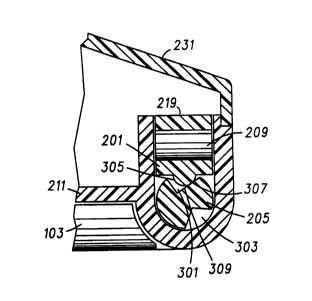
A more detailed view of the detenting hinge
apparatus is illustrated in FIG. 3A and FIG. 3B. FIG. 3A
illustrates the position of recesses 301 and 303 when the
flip element 103 is in the closed, on-hook position. FIG. 3B
illustrates the position of the recesses 301 and 303 when
the flip element is in the open, off-hook position. When
opening the flip element 103, the detent follower 201
moves out of recess 301 in the hinge shaft 205 and onto
the full diameter surface of` the shaft 205. The spring
209, captivated between the retainer 219 and the detent
follower 201, constantly forces the detent follower 201
against the hinge shaft 205. As the flip element continues
to rotate to the open or off-hook condition, the detent
follower cam 201 continues to push against the hinge
1 S shaft 205 and then forces itself into the recess 303. The
force of the detent follower cam 201 in the recess 303
holds the flip element 103 in the desired position.
Recesses 301 and 303 each have two essentially
planar surfaces in which the planes of the surfaces
intersect to form an angle. The detent follower 201 has a
curved surface 305 engaging the hinge shaft 205. When the
flip element is in the closed or on-hook position, a first
portion 307 on the curved surface of the detent follower
305 presses against one of the essentially planar surfaces
309 of the recess 301. The pressure of the detent
follower 201 against the one surface 309 of recess 301
preloads the flip element 103 against the front housing
211 of the portable unit 100. This novel approach of
applying a preloaded force causes the flip element 103 to
remain tight against the planar surface of the front
housing 211 without using any additional latching
mechanisms. When the flip element 103 is in the open or
off-hook position, the first portion 307 of the curved
surface 305 of the detent follower 201 contacts a first
lO 2077333
essentially planar surface 311 of recess 303. Likewise, a
second portion 308 of the curved surface 305 of the detent
follower 201 contacts a second essentially planar surface
313 of recess 303. The curved surface 305 of the detent
S follower 201 is assured of making contact with the recess
303 at two locations because the curved surface 305 seeks
to center itself within the angle formed by the essentially
planar surfaces 311 and 313 of the second recess 303.
Therefore, the flip element 103 is stabilized in its open,
1 0 off-hook, position without excessive play.
The design of the hinge shaft 205 allows the flip
element 103 to open or close without further user
assistance when it is within 45 of either position. It
should be noted that recesses 301 and 303 have an edge
1 5 radius at the corners where the planar surfaces intersect
with the full diameter surface which enables the curved
surface 305 of the detent follower 201 to smoothly move
from one recess 301 to the other recess 303 as the flip
element 103 is rotated from its closed to its open
2 0 position, respectively. The detent follower 201 is formed
of a flexible, plastic material such as, for example,
"Delrin" (TM), or some other such material having low
friction characteristics. The flip element also has the
ability to over travel the open position by an amount such
as 30, if forced, and return to the open position
automatically when the force is removed. The possibility
of breaking or jamming the positioning mechanism is
removed by having the entire detenting hinge apparatus
contained within the hinge cavity of the front housing.
FIG. 4 illustrates an end view of the hinge shaft 205
as part of the hinge portion 112 of the flip element 103.
Recesses 301 and 303 each have its essentially planar
surfaces intersecting at an angle ~, 90 for example.
Alternate embodiments may have recess 301 forming an
1 1 2077333
angle which is different from the angle produced by recess
303. Virtual radial lines 401 and 403 are drawn from the
center of the hinge shaft 205 through the vertex of recess
301 and 303, respectively. The virtual line 401 drawn
S through the vertex of recess 301 splits angle (P such that
the angle between the first surface 309 of recess 301 and
the virtual radial line 401 is somewhat less than half of
the full angle ~ represented by (~/2~. The offset angle,
(~/2~, (40o in the preferred embodiment where a= 5)
1 0 enables the portion 307 of the curved surface 305 of the
detent follower 201 to only engage the recess 301 at one
location on the first surface 309 such that the flip
element 103 is preloaded against the front housing in its
closed position. The virtual radial line 403 bisects angle
1 5 ~ in recess 303 which enables the first and second portion
307 and 308 of the symmetrical curve surface 305 of the
detent follower 201 to contact the first 311 and second
313 planar surfaces, respectively, to stabilize the flip
element in its open position. The angle ~3 between virtual
radial line 401 and 403 is predetermined to locate the
obtuse angle of the flip element with respect to the front
planar surface of the body of the radiotelephone when the
flip element 103 is in its open position. In the preferred
embodiment angle ~3 equals 150.
A cross sectional view of the hinge portion 112 of
the radiotelephone of FIG. 1 is illustrated in FIG. 5. The
stack up of the detenting hinge assembly along the common
axis 233 is clearly represented. Hinge shafts 205 and 207
of the flip element are positioned within the hinge cavity
203 such that they lie on opposite sides of the pin 213.
Hinge shaft 205 has recesses 301 and 303 as described in
the end views of the hinge shaft 205 in FlGs. 3A, 3B and 4.
Hinge shaft 207 has recesses 501 and 503 located in a
corresponding opposite position and having essentially the
1 2 2077333
same shape as recesses 301 and 303, respectively, on
hinge shaft 205. The detent follower 201 has the curved
surface 305 and a corresponding curved surface 505 having
essentially the same shape as curved surface 305 and
S located opposite the pin 213. The curved surfaces 305 and
505 of the detent follower follow the surface of hinge
shafts 205 and 207, respectively, as the flip element is
rotated. As the flip element is rotated from its closed to
a partially open position, the curved surfaces 305 and 505
1 0 slide up one side of the recesses 301 and 501,
respectively, onto the full surface diameter of the hinge
shafts 205 and 207 respectively, to fully compress the
spring 209. As the flip element is fully opened to its
desired obtuse angle to the plane of the front housing 211,
1 S the curved surfaces 305 and 505 slide down one side of the
recesses 303 and 503, respectively, from the full surface
diameter of the hinge shafts 205 and 207 respectively, to
release the full compression on the spring 209.
The retainer 219 captivates the spring 209 and
2 0 compresses the spring 209 against the detent follower
201 thereby causing the curved surfaces of the detent
follower 305 and 505 to press against the surfaces of the
hinge shafts 205 and 207, respectively. Note that when
the spring 209 is compressed and the curved surfaces 305
and 505 of the detent follower 201 are within recesses
301 and 501, respectively, the pin 213 only protrudes
through a portion of the detent follower 201. Therefore,
the detent follower 201 is slideably constrained as the
flip element rotates without contacting the spring 209.
3 0 Therefore, a detenting hinge apparatus of simple
construction as well as of smaller dimensions has been
disclosed. Novel elements of the preferred embodiment of
the present invention comprise hinge shafts having
recesses integral to the hinge portion of the flip element,
1 3 2~77333
convenient single common axis assembly of a few simple
parts, the detent follower preloading the flip element
against the body portion when the flip element is in the
closed position and the detent follower stabilizing the flip
5 element in its open position without excessive play.
What is claimed is: