Note: Descriptions are shown in the official language in which they were submitted.
2077390
POS~G STATION
TECHNICAL FBLD
The present invention relates to a phologl~)hic L~l~il studio, including a posing
station utilized in the por~ait studio.
S BACKGROUND OF THE INVENI~ON
Photographic studios typically are designed to be flexible in order to accommo~l~te
taking po,l,~ of entire f~milies, as well as smaller groups, individuals or babies.
While the type of elluip",enl and flexibility of various polll~il arrangements vary,
portrait studios typically have several things in common. The subject or subjects to be
photog,aphed are aesthetically po~itione~ on or around a chair, stool, or other posing
station, and a backdrop containing a selected background design is placed behind them.
Skobe lighting is used to propelly illumin~te the subjects, usually from at least two angles
to create the proper balance of light and shadows. After the equipment is readied, several
poses are usually taken.
The subjects wishing to have their pictures taken can range from a group or family
to a single individual or a baby. The posing area and overall porkait studio, therefore,
should be readily adaptable to the variety of potential subjects. Prior art posing st~tions,
however, such as the one depicted in U.S. Patent No. 4,166,687, are often designed for
2077390
~~nly one type of subject, such as infants or toddlers, thereby restricting the range of
subjects that can be phologl~hed.
Even those studios that are able to photogl~h di~eçel,t types of subjects have
signifi~nt drawbacks. For e~mple, babies are a frequent subject of photogrdl~hs and a
5 posing station must ensure the safety of the child while the photograph is being taken but
not distract from the picture by having safety fealules visible in the picture. The posing
station must also be able to acco.n...od~te groups of people where some people will
iti(?n~lly be ~t~n~ling and some sitting. Most prior art posing st~tion~ either are not
able to accommod~te both babies and large groups or else are convertible between the
10 different setups only with great difficulty.
To be profitable, poll-~l studios must operate quickly and efficiently. A studio
should be simple to operate and be easily adaptable to different photograrhic ~tting~.
Furthermore, the studio should be able to operate under a variety of con~itions and with
as few adj~lstm~nt~ as possible. Many of the prior art studios require the photographer to
15 reposition the backdrops, lighting and camera between each s~alale shot, all of which
leads to lost time and productivity, as well as increasing the likelihood of errors in the
photographs.
A need exists, therefore, for a self-suppolled portrait studio and related equipment
that can accommodate a large variety of pOllldil subjects in a quick and efficient manner,
20 and that can be properly adjusted with a minimum amount of mental or physical effort
from the photogldpher.
~ ~739~
,~
SUMMARY OF THE INVENTION
The invention provides a photoglaphic posing station which can be inte~;~dtGd into
an overall pOllldit studio. The posing station inGludes a st~tion~ry base and a removable
platform. The base and platform include positioning means for positionin~ the platform
on the base. The positioning means typically comprise pegs eYt~n~ing from the bottom of
the platform and cGllGsl)onding holes on the base. By placing the pegs into the holes, the
plafform can accu,dtely and quickly be placed in its proper oriPnt~tion on the base.
A span is movable betweGn a first eYtendçd position and a second stored position,
and is at least partially suppo~led by the platform in the e~t~nded position. The span
allows the posing station to easily adapt to a variety of photographic subjects. For
e~mple, if a baby is to be photographed, the span is eYtended and the baby is placed
approxim~t~ly in the center of the rather çYp~n~ive posing station surface. If, however, a
group is to be photographed, the span is retracted to its stored position and the group
members may be arranged so that some are sitting on the platform and some are st~n~ling
behind the platform.
In the pl~;Çelr~d embodiment, the base is ~tt~che~ to a frame to which is also
~tt~chçd at least one backdrop, the subject lighting, and preferably, the camera. In this
way, the distances between all the major studio components remain fixed and, once set,
require no further adjustmçnts
2û Also in the preferred embo lim~nt, the studio includes a central procescing unit
with data storage capacity. Any studio operations or variations, such as the sequencing
and preparation of pictures, is performed by the central proce~ing unit, thereby freeing
2077390
~he phologla~her of these tasks and helping to ensure that high quality photog~a~?hs are
con~ictently produced.
BRIEF DESCRIPTION OF l HI~ DRAWINGS
Figure 1 is a pe~pe~ e view of the po~ studio.
Figure 2 is a ~ ti~e view of the posing station with the span re~cte~.
Figure 3A is a pel~;ti-~e view of the posing station with one pldt~llll removed.Figure 3B is a p~ re view of the back of the platform showing the
positioning pegs.
Figure 4 is a partial cross~ tion~l view of the polllOit studio.
DETAILED DESCRIPTION OP ~ INVENTION
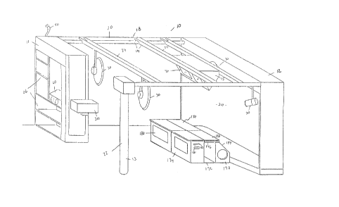
The photographic app~dlus comprising the integldled, self-s.ppolled pol~
studio, generally design~te~ 10 in Fig. 1, includes a frame 18, a camera 310, a backdrop
210, lighting 30, a posing station 170 and an optional video monitor 40.
The frame 18 offers support to the other co.l,ponents, defines the environment in
15 which the photog~dphs are taken, and spatially locates the various copollents with
relation to one another. The frame 18 is desirably made up of a pedestal unit 11, a
background unit 12, a post unit 13 and a rail system 14. These units define generally the
boundaries of the studio. The rail system 14 links the units together and acts as a conduit
for the electrical wires and supports the overhead subject lights 30 as well as the video
monitor cabinet 15. The studio's dimen~ions can vary and the post unit 13 and the
pedestal unit 11 can be used inte~hangeably. The rail system 14 is made up of
longit~din~l beams 20 which desirably link the background unit 12 to the pedestal unit 11
2077390
~-and the post unit 13, and lateral beams 24 which link the longihldin~l beams 20. The
beams can be made of tclescopic mPmbers, the smaller Ille.llbe ~ slidably residing within
the larger ones, which allow the studio to adapt to the size of the area in which it will be
tP~. In the pl~;r~ ed embodiment~ however, the lateral beams 24 are at a fixed length
S of 8 feet and the longit~din~l beams 20 are constructed of two sep~ate Ille,-lbe.~, each
con~isting of a pre-set length. In the pl~fe.,~d embo~1iment~ the overall dimPnsions of the
portrait studio are desirably 8' wide by 15' long by 8.5' high. These ~imPn~ions provide
ample area for most family settings while allowing the studio to be erected in a
reasonably small room.
The po~ studio desir~hly cont~inS one master column 22 constructed of a
suitable design and m~tPri~l. In the pr~_felled emb~imPnt the pe~est~l unit 11 con~in~
shelving 26 which allow the photogldpher to store equipment, inventory or props in a
convenient yet unobtrusive manner. The shelving 26 can also house a central pf~ces~;ng
unit 60. The pedestal unit 11 and the shelves 26 collt~ined therewith, do not need to be
15 uniform in size or shape and can be modular to allow for easy adaptation for storage of
different types of equipment.
As mentioned, the beams 20, 24 desirably link the units and lollgit-l~in~lly and
laterally traverse the studio 10. The subject lights 30 can be carried by either the
]ongitu~lin~l 20 or lateral beams 24. These lights ilhlmin~te the subjects on the posing
20 station 170. Two lights are typically employed for sufficient frontal li~hting and the
present invention is capable of supporting additional lights, such as background lights,
hair lights, side lights, etc. The number and wattage of the lights will be dictated by the
individual studio requirements and the particular photographer's needs.
- ~û 77 ~9~
A posing station 170 is sib)at~ on the floor of the studio between the camera 310
and the backdrop 210. The posing station 170 con~ of at least one platro,... 174 with
a span 176, a rear support 178 and a base 172 which is ~tt~h~ to the bac~ nd unit
12.
S The ~Irullll 174 and s.~ l 178 are located on the base 172. Any suitable
configuration and m~tPn~1 capable of s.,~pG,ting the co-..pone~,ts will suffice for the base
172. Preferably huw~i~r, it is forrned of Ple iglq~or imilar InqtPn~l) and is gener~11y
rectangular in shape.
T~ted on the rear of the base 172 is a support 178. The support is desirably
10 ~l~ nenlly affL~ed to the base 172 by a~p~pl~te ~tt~f~hm~nt means. In the pl~f~lled
embo~im~nt, the support 178 has a flat top surface 190 and a front surface 192 which is
preferably vertical. The back surface 194 slopes downwardly from the top 190 opp~;,ile
the front 192 and t~ ~. ;n~tes in a back vertical section which is parallel to the front
surface of the s.lppcll 178. In one ~fc.led embodim~nt, the height of the support 178
is desirably applo~ ely 21 3/4 inches while the length of the support 178 generally
co"ejponds to the length of the base 172.
In a preferred embodiment, the platform is comprised of two sep~te but virtually
identiç~l platforms 174 located on the end of ~e base 172 a set ~i~t~nce from the S.l~p
178. The platforms 174 sit ~djaç~-nt to each other and, like the support 178, dej~ably
20 extend the entire width of the base 172. ~lthough desirably two platforms are used (for
ease of moving, etc.), any suitable number of individual sections could be used. The
platforms 174 preferably are generally rectangular shaped, desirably 22 1i2 inches by 12
inches by 22 1/2 inches, although other suitable configurations or ~lim~.mior~ could also
be used.
~Trade-mark
A
2077390
. ..
tachPd to each of the platforms is a span 176 that allows the posing station to
~~~o~ lodale a wide variety of po~ subjects. The span 176 is preferably attached to
the platform 174 at the platform's u~ ".o~l edge on the side closest to the support 178.
Any suitable ~tt~hmP-nt means can be employed, however, in the pf~Ç~led embo~imPnt,
S the span 176 is ~tt~ch~ to the platform 174 Ihr~ugll the means of a hinge 188 (desirably
a piano hinge).
The span's length and width is similar to that of the top surface of the platform
174. Thus, when the hinge 188 is closed, the span 176 is capable of resting on the top of
the platform 174 with only a slight ovefl.ang as shown in Fig. 2. Conversely, with the
hinge 188 in its fully opened position, the span 176 extends oulw~dly away from the
platform 174 towards the rear of the base 172. ~ltern~tPly, the span might be stored
within a recess in the platform 174 and be slidably e~tend~hle oulwar~ from the back of
the platform 174.
The platforms 174 are placed a set ~lict~nce away from the support 178 so that an
aisle exists between them. The width of the aisle between the platforms 174 and the
support 178 is desirably such that the spans 176 rests upon the top surface of the support
190 when they are fully extended from the platform 174. The flat configuration of the
s.l~poll's top surface 190 ensures that the spans 176 remain level when extended from the
platforms 174.
~ In the p~fe,fed embodim~nt~ the back vertical surface of the platforms 174 do not
extend all the way down to the base 172. Tncte~d, a gap of approximately 4 inches is
provided in the platform's base so that the toes of people standing in the aisle can
comfortably be placed under the plalÇol",s 174.
- - 20 77 3gO~ ~
"_
The two positions of the spans 176 (e~t~nded across the aisle and resting on top of
the platrol-l- 174) aUow the posing station to acco.. ~l~t~ a range of po~ ,l subjects.
Group phologl~hs can be taken by having part of the group stand in the aisle behind
others sitting on the pl ~ rv~ ...c Conversely, e~tPn~lin~ the spans 176 to bridge the aisle
S produces a rather c-l~n~;ve surface on which individuals, babies and small children can
be l)hotog.~h~d.
The ~ nC;ve area created by the top of the pl~,ro~ 174 and the ë~t~-nd~ spans
176 can de~ir~bly be co~i~ by a soft ~n~t~n~l or ~lding~ such as a foam rubber pad,
~l~ling or the like, to provide a col,lfolt~ble yet p~tecliv-e surface for the ~lll~l
10 subjects that wiU sit or lay upon it. In the lllcf~lcd embo~iment, a pliant high density
foam mat 198 (e.g., of the type used in athletic mats) of ap~lo~ lely 1 1/2-inch
thi~ ness is placed over the l ~s~ surface. The mat 198 desirably extends partiaUy
beyond each of the edges of the surface so that the platlol.n's corners are not ~_,.yos~.
The mat 198 can be- secured to the surface in any suitable ~--am~r, but in the plefe,lcd
15 embo lim~nt, four VELCRO-type hook and loop strips, two on each side of the hinge
188, are ~tt~ h~ to the c;-l)03~d surface while colrcsponding StlipS are ~tl;.~l-~ to the
underside of the mat 198. By placing the strips in a symmetri~l pattern in relation to the
hinge 188, the mat 198 can be placed on the surface without conce... for its ori~nt~til?n
A second protective cover can also be placed on top of the mat. The cover should
20 desirably be comfortable to lay or sit upon yet also look attractive in a photograph. In
~e pl~f~ed embodiment, a soft velvet cloth is used. The cloth may include a
friction-inducing bottom surface that prevents it from slipping with respect to the mat
198.
~Trade-mark
2077390
The underside of the spans 176 can also be cove~ed with p~ ing so that when the
spans 176 are rel.~cl~, people sitting on them will be ccl--fclt~ble. Any suitable
matçri~l will suffice and in the preÇehed embo~iiment~ a resilient foam-filled pad covered
by durable vinyl is used~
In the prerelled embodimçnt the platforms 174 are capable of being removed and
then replaced in precisely the same loc~tion on the base 172 through use of positioning
pegs 184 located on the bottom of the plalÇulnls 174, and co,les~ 1ing receptacles 186
located in the base 172. The pegs 184 plef~ably are located on the platform in an
asymmet iç~l pattern with respect to at least one of the platform's axes. This ensures that
a platform 174 can be position~d with respect to the base 172 in only one way and that,
therefore, the photogl~her cannot ~ident~lly replace a ~lalÇol.ll 174 backwards.poSitioning the platforms 174 on the base 172 in a consi~tçnt "lann~ ensures that the
spans 176 and storage colllp~ll.lents, ~is-uss~ below, are always coli~lly oriented.
The pegs 184 and co~responding receptacles 186 can be arranged in any pattern that
achieves the above results. Similarly, any suitable number of pegs 184 and receptacles
186 can be used. In the prerell~d embo iim~nt, four pegs are positioned on the platforms
as shown in Fig. 3B.
The shape of the positioning pegs and receptacles is not limited to those shown in
Figs. 3A and 3B. There are numerous varieties of peg and receptacle arrangements that
would achieve the desired results. In the preferred embodiment the pegs 184 consist of
pan head screws threaded into the bottom of the platforms with their heads e~ten~ing
about l/8n - 1/4". The receptacles 186 are shaped accordingly to receive the pegs 184,
and consist of round holes drilled into the base 172. Obviously the pegs 184 could
aIternately be carried by the base 172 with the receptacles 186 being located in the
2~77390
l~latrol"ls 174, or other equivalent means for locating the pla~Ço~n,s 174 on the base 172
could be utili7~d.
The vertical surfaces of the platÇol."s 174 are desirably l~c~ to forrn cavitieswhich may be used as storage co",p~ll"ents 180 where equipment or props can be kept.
S The cûlll~ lnen~ 180 are particularly helpful when a pulLI~it of an infant or toddler is
being taken. During such times, the photoglapller will typically work in front of the
child and use props such as hand puppets or stuffed ~nim~l~ in an attempt to get the child
to smile. By having storage cû"~p~l~"ents in the front of the plalÇol"~s, the phologlapher
can conveniently reach the toys (which are otherwise out of sight of the child) while
~ ining attentive to the child.
As a further convenience, in the plefelred embodiment, facial tissues are
ible from a holder 181 in the sides of the platforms 174. Additional storage
co",~l",ents can also be located on the platrol,ns 174 for other objects or ~uip",ent.
Simil~rly, the support 178 is desirably hollow for the storage of equipment and, as
descnbed below, a background light. ~ndl~s 182, which aid in the po~itioning andh~n~ling of the platforms 174 on the base 172, may also be provided on the two lateral
sides of the platforms 174 near the platforrn's top.
In a preferred configuration, a background light 150 is mounted within the support
178. The light 150 c~n be ~tt~ch~d to the support 178 in any suitable manner but should
desirably allow the light 150 to illuminate the central portion of the backdrop 210. The
background light 150 may also include an automatic or manual gel changer 151 fortering the color of the light used to ill~lmin~te the backdrop 210.
In a preferred embodiment, nine gels of different colors and densities are
connected end to end to form one continuous roll. Rollers are placed at opposite ends of
~ 77 3~
the bacLglound light surface and the gel roll is wound up upon the two rollers and over
the bac~r~nd light 150 to forrn a scroll. By rotating the rollers, any of the gels in the
roll can be positionf~l over the bac~l-,und light lS0. The rollers can be rotated m~n~ y
or they can be . .oto.;,~ Any s~lit~hle . oto.;~ method will suffice inr1~1rting the
S use of a stepper or ~nchr~no.~s motor. However, in the pfe~lled embodim~nt~ a DC
gear head motor is employed.
Also in the plef~,l~ e,llbo t;...f ~, the ch~nei~ of the gels is ~lolllaled by
Iinking the motor to a central ~lw~ unit 60 or co~ ul~r. The gels are ~lo~ly
po~;l;on&~ by means of a sensor and/or det~tinn e~lui~ll,ent. ~ the pl~f~ d
10 embo timent, bar codes or patches are placed on the individual gels and a sensor capable
of reading the bar codes or patcl e s is linked to the col"~uler and placed acco~ingly near
the gel changer. In ~1te.~ ;ve enlbod;lllpnt~t a ...~h~nir~1 sensor is used with a stepper
motor or an optical scann~ is used with a synchronous motor. The nulne ~us gels and
bac~r~ps available can be used in combil~tion to providé a wide variety of poll,~il
15 back~roulld colors.
The plalro~llls 174, spans 176 and support 178 should all be constructed of a
lightweight yet strong m~teri~1 It is i~l,pol~nt that the platforms 174 be lightweight so
that they can be easily moved, yet they must m~int~in the strength to support the weight
of the children and adults who will be positioned on top of them. Furthermore, all of the
2~ above components should desirably have smooth surfaces and rounded or otherwise
protected edges to reduce the possibility of injury. In the plerel~d embodim~nt, the
components are made of plywood, particle board, or similar material, desirably covered
with ~el~min~(or similar smooth, durable material) which is l~min~t~1 to the plywood.
~Trade-mark
2077390
~.,.
The backdrop 210 is positil)n~ within the background unit 12. On the backdrop
210 can be painted or ~tt~rh~d various color arrangen,ellts which serve as backgrounds
for the ~~ s that are produced in the studio. The backdrop 210 desirably incl~des a
stabilizer or steering ~ ~h~ m to ensure that the bacl~lr~s are plopelly po~itioned
5 behind the posing station 110.
To façilit~tç the positioning of the ~ it subjects, a focus positioning light 37
can be ~tt~ched to the studio above the posing station 110. The focus posiboning light 37
projects the image of its fil~mPnt upon the posing station 110 desirably at a predetermined
focal point. This allows the operator to continuously prop~lly position the subjects on the
posing station 110. The video monitor 40 also desirably assists in the positionin~ of the
subjects. In the pl~fe,led emb~iment, the image seen by the camera 310, is displayed
by the video monitor 40. The photogla~her can then adjust the camera 310 and/or the
subjects to the proper positions for the phologlaph. Also in the pref~r~;d emb~limPnt,
the video monitor cabinet 15 includes both a hori7Ont~l and vertical color monitor. The
camera 310, of the type typically found in the art for taking ~lllails, is desirably
operatively connected to both the video monitor 40 and the subject lighting 30 through
a~pf~liate electrical means. The camera 310 also desirably incl~ldes a remote control to
enable the photographer to walk about the studio and/or stand or kneel adjacent the posing
station 110 (particularly for small children) as well as to raise and lower the camera 310,
move the camera 310 from side to side and zoom the camera 310. Additionally, the
remote control could allow the phologl~pher to focus the camera 310 if such a function is
desired.
The polll~it studio 10 is a relatively compact system which can easily be installed
in a short time. To construct the portrait studio, the frame 18 is first erected by
~ 7~ 3~0 ~:~
-
posihon;ng the pedestal unit 11, post unit 13 and bac~und unit 12 and ~tt~hing the
rail system 14 to these units. The subject lighhng 30 and video ...on;l~r cabinet 15 can
then be ~tt~thed to the overhead bearns 20, 24 at the desired lo~tion~.
The posing station 170 is assembled by col~nP~ g the base 172 to the bacl~r~ui~d
S unit 12. The bac~r~und light 150 may be suitably ~h~d within the suppo l 178 and
the support 178 in turn secured to the base 172. The plalroi,..s 174, with their span 176,
can then be posihion~ on the base 172 by ins~ g the po~itin~in~ pegs 184 on the
bottom of the pL~ lllS 174 into the l~ptacles 186 located on the base 172.
After the posing station 170 is set up, the camera 310 and lights 30 are el~tri~1ly
10 cor~n~d to each other and a central et~-tri~l circuit 50 ~w~ g through the frame 18.
Along with the camera 310 and video .~.on;lJ~r 40, the elçctn~l circuit 50 of the pOl~
studio 110 dçsir~hly inCludçs the ov~l-ead subject lights 30, the bacL~lou..d light 150 and
gel changer 151 and any motoli~d bacL~r~ps ~at may be intcluded in the studio. The
el~ t circuit S0 is desirably in~e~.~t~ into a single circuit l~---n~l;ng in a
convention~1 110V plug that can be inserted into a standard el~ri~l wall outlet,
~lpplying all the power needed to run the entire portrait studio 110. Furthermore, the
individual co~ )onellts of the poll~ studio 110 desirably have the capacity to be linked
with a centraI p~ ing unit 60 which can coor~ ate their operation, function, and
Sync~ 7~l ;nn .
Once the po.l,~l studio 110 has been readied, the taking of photographs is a
simple and convenient procedure for the photog.~ph~r. In the pr~fe -t;d embo lim~nt, a
gray card 25 is sit~l~ted behind the video monitor 40 so that, when lowered, it hangs
above the posing station 110. The gray card 25 can be used by the photographer to
gather a reading of the light conditions within the portrait studio l lO and thus standardize
2077390
~-.he photographic con~itions. A~~ d, the gray card 25, can be replaced unobtrusively
behind the video monitor 40.
The subjects are arranged on the posing station 110 in a manner that is
a~sth~ti~lly pleasing considçring the size of the group and ages of the subjects. The
S position of the span 176 with respect to the platforms 174 will depend upon who the
il subjects are. If a baby or a small child is to be photog,~phcd, the spans 176 are
~Yt~-n~ed to cover the aisle between the platforms 179 and the s.lppoll 178, and the baby
is placed in the middle of the eYp~n~e~d surface. The photogl~)her typically will be
positioned in front of the child but below the level of the camera lens and can control the
10 camera with the remote control device, preferably zooming the camera 310 in and out and
snapping the picture. The photog,~pher may employ the use of props, such as hand
~u~peLs or stuffed ~nim~l~, to get the child to smile for the camera 310. These props can
be conveniently stored in the col~-palL"~ents 180 located in the front of the platforms 174
where they are easily ~cessible.
I5 If a group photograph is desired, the span 176 may be retracted to reside on or
within the platforms 174, thereby eYposing the aisle. Taller individuals can then stand in
the aisle while the other members of the group can sit on the platforms 174. This creates
a typical two-level effect whereby all the subjects' faces can easily be seen. The
plaL~ol",s 174 may also be removed from the base 172 if a wider space is needed (such as
20 for photographs with large props or to be acces~ible to wheel chairs). Once the subjects
are collbclly posed, the photographer takes the picture.
While a preferred embodiment of the present invention has been described, it
should be understood that various changes, adaptations and modifications may be made
14
2077390
~erein without departing from the spirit of the invention and the scope of the appended
claims.