Note: Descriptions are shown in the official language in which they were submitted.
WO 91/13733 P(."T%US91/01569
1 9 r~ ~..~~ ~c
SLITTING hPPARATUS FOR CORRUGATED
PAPERBOARD AND THE T.IhE
Background of the Invention
The present invention relates to an apparatus
for slitting a traveling corrugated paperboard sheet
and, in particular, to a thin rotary blade slitting
apparatus for substantially improving the quality of
the slit.
Apparatus for longitudinally slitting a
continuous traveling sheet or web of corrugated
paperboard is well known in the art. Such apparatus is
often combined with a ~aechanism for simultaneously
providing longitudinal score lines to the advancing
sheet, which score lines facilitate subsequent folding
l~ in the construction of boxes or the like. Thus, a
combined "slitter-scorer" .utilizes pairs of rotatable
cutting tools and scoring tools disposed in the path of
the advancing sheet, with one tool of.~ each pair
disposed on an oppos_te side of the sheet.' T~-pica.lly,
rultiple slitting tools are. mounted coaxially and
laterally spaced across the width of the sheet and,
likewise, aultiple scoring tools are also coaxialiy
mounted and spaced across the sheet width.
Tn the prior art, earn pair of upper and lower
5 slitting tools is cisposed with overlapping radial
cutting edges between which the advancing paperooard
sheet is roved to provide a continuous cut. Although
the operation is car.~aonly referred to as "slitting",
the cutting tools in fact shear the roving sheet
=~ causing a relative vertical cisplacerent o~ the cut
edges fron one ano~her. As the thickness of the
corrugated board being processed increases, the c~,:ts
tend to bacorae morn ragged, the edges ten: to be
crushed, and the cut quality tends to degrade
2~ significantly. Another problem commonly associated
WO 91/13733 ~ ~~ ~ r.,, ~ PCT/US91/01569
a a __
~, ~: _2_
with rotary shear cutting of corrugated board is the
generation of dust. Fine paper dust is a very serious
problem which nay result in clogged filters on air
handling systems, hazardous air quality for workers,
contamination of electronic and other equipment, and
even explosion or fire hazards.
Other methods and apparatus for cutting
corrugated paperboard have been developed to eliminate
or alleviate some of the problems associated with
rotary shear cutting. Thus, it is known to utilize ~~
high pressure water jets to cut paperboard. ~aater jets
provide high quality cuts, but the equipment k~as an
extremely high initial cost and requires costly
maintenance.
U.S. Patent 4,627,214 shows a slitter-scorer
apparatus of one prior art construction in which the
board is sheared by passage between the, overlapping
edges of a pair of rotary cutting knives. Even when
such cutting knives are properly adjusted and main-
tained in a sharpened condition, their use to slit
heavier double and triple wall board has been less than
satisfactory. l -
There is a head, therefore, for an apparatus
which will provide a~ clean, dust-free cut in an
efficient and econamical manner.
Summary of the Invention
In accordance with tire present invention,
corrugated paperboard is cut with a true slittin5
technique in an apparatus in which the advancing sheet
or web of paperboard is advanced through a sharp, thi.~.
circular Made running in the same direct_on as the
paperboard sheet but at a much higher speed, with the
aoard supported below the blade by rollers on bhe
underside.
WO 91/13733 ~ ~ ( ~ '~ ~ ~ PGT/US91/01569
_3_
In its basic embodiment, an upper tool head is
mounted over the sheet and is laterally translatable
across the width of the sheet to position the tool head
on the desired cut line. An annular cutting blade is
rotatably attached to the tool head such that the
peripheral cutting edge of the blade extends downwardly .
beyond the opposite side of the board sheet. A lower
tool head or counterhead is mounted on the underside of
the sheet and is also laterally translatable across the
width of the sheet on a line parallel to the line of
lateral translation of the upper tool head. Roller
means are rotatably attached to the counterhead and
present a cylindrical outer surface which is positioned
to make tangent contact with and support the underside
1~ of the sheet. The roller means are provided with an
annular circumferential slot in the outer surface,
which slot has a width slightly greater than the width
of the blade and is positioned to receive. the rotating
blade edge therein. Thus, the overlapping blade and
roller means form a nip into which the moving sheet is
fed for slitting. Drive r.~eans are provided to rotate
the slitting blade edge in the direc~ion of movement of
the sheet and at a speed greater than the speed of the
moving sheet. fieans are also provided for applying a
lubricant to the cutting edge of the blade which
prevents a build-up on the blade of starch fron the
glue used to hold the components of the corrugated
board together.
Preferably, the supporting roller means is
formed fron a pair of coaxially maunted rollers which
are axially spaced such that their adjacent interior
faces define the annular circumf=rential slot for
receipt of the slitting blade. Tne rotational axis of
the rollers is preferaaly offse~ in the upstrean
3a direction, witn respect. to movement of the sheet, from
WO 91/13733 ~ , ~~ ~;. PCT/US91/01569
_4_ _
the rotational axis of the blade. ~.7.so, the dianeter
of the rollers is less tnan the diameter of the
slitting olade and the offset position of the rollers
is established such that the line of tangent contact of
the rollers with the underside of the sheet defines a
line which is normal and tangent to the blade edge
where it exits the lower surface of the sheet.
The adjacent interior faces of the supporting
rollers defining the circumferential slot preferaoly
diverge in a radially inward direction. Alternately,
the adjacent interior faces of the rollers nay be
recessed to define open interior portions: In either
embodiment, the rollers are relatively more open in a
radially inward direction to provide space for the
accumulation of paper scraps, dust and the like.
Preferably, a stripper bar is attached to the roller-
supporting counterhead and extends through the
circumferential slot to present an edge defining an
acute angle with respect to the plane of the sheet and
to diverge therefrom in the downstream direction of
a~ sheet novement. The combined rotary movement of the
blade and rollers tends to cause accumulating paper
scrap and the like to move along the stripper bar and
out of the slot between the rollers.
~n the preferred embodiment, the lubricant
applying. means comprises a wick nolcie= which is
attached to the upper tool head and presents a pair of
spaced generally parallel legs positioned to straddle
the cutting edge of the glade. A wick is mounted on
the inside of the legs of the wick holder to maintain
contact with the blade edge while the blade is rotating
anc metered.amounts of a lubricant are suppliec to the
wick. The wick holder a pivotally attached to the
tool head for movement between the operative
lubricating position and an inoperative position spaced
WO 91/13733 PCT/US91/U1569
-5-
radially beyond the blade edge to facilitate blade
changing.
The slitting apparatus oz the preferred
embodiment also includes means for sharpening the blade
edge on the fly or while the blade is rotating. The
sharpening means includes a bracket attached to the
upper tool head, a rotary sharpening tool pivotally
attached to the bracket for movement between an
operative position is contact with the cutting edge of
the blade and an inoperative position out of contact
therewith, means for moving the tool between its
operative and inoperative positions,' and neans for
rotating the tool when it is in its operative position
in contact with the blade.
. The longitudinal slitting apparatus of the
preferred embodiment is utilized on a slitting appara-
tus of the prior art type in which a plurality of slits
are provided spaced across the width of a traveling
sheet or web. Thus, an upper support structure is
positioned to overlie the advancing sheet,and has an
upper guide means defining a linear path across the
width of the sheet. A plurality of upper too l heads
are mounted on the upper guide means such that each of
the .upper toal heaas may be individually moved along
:,he linear path across the sheet. A olade holder is
~rotatably attached to each upper tool head an;:
positioned for rotation an a comaon axis. A drive
shaft is positioned on the common axis of the blade
holders to simultaneously drive the same and to support
the tool holders and uppar tool aeads for :,iovenent
along the upper guide means. A th_n annular slitting
blade is carried on each of the blade holders, each
blade pr'seriting a downwardly depending circular
cutting edge which extends below the bottom face of the
sheet, as previously described. A lower suppor~
WO 91/1 ~7,~3h ~ ~ ~ ~ PCT/US91/01569
G.~ ,, ~
-6-
structure is disposed under the sheet anc includes
lower guide means defining a lower linear path across
the width of the sheet and parallel to the uppar linear
path. A plurality of lower tool heads are n~unted on
the lower guide means with each of said lower tool
heads individually movable on the guide means along the
dower linear path. Roller means are rotatably attached
to each of the lower tool heads, in a manner previously .
described, with the outer surface of the roller posi-
tioned to make tangent contact with the underside of
the sheet. An annular circumferential slot is provided
in the outer surf ace of the roller means, the slot
having a width sufficient to receive therein the
portion of the blade edge extending below the sheet.
Means are providing for advancing the sheet over the
roller means. and into the blade cutting edges, for
rotating the drive shaft to move the blade cutting
edges at a speed greater than the speed of the roving
shee , and far applying a lubricant to the blade
cutxing edges.
Preferably, each upper tool head includes
separate positioning ~aeans~for moving the tool head
along the upper guide means and for carrying therewith
its'corresponding lower tool head along the lower guide
ZS means. In its most simple embodiment, the lower tool
head is carried ov virtue of contact between the
slitting blade anc the roller means. To provide a
greater gearing surface for carrying contact between w
the blade and the roller means, each of the roller
neaps nay be pivotally attached to a lower tool head on
a pivot axis aarallel to the axis of rotation of the
roller Zeans to increase the amount of the olada edge
which is received :.n the circuaferential slat in the
roller means.
WO 91/13733 PGT/U891/01569
°7- ~ ~ ~'; :3 y
Rotation of the slitting olades at a speed
substantially in excess of the speed of the moving
paperooard sheet, e.g. two or more times faster,
provides a clean razor slit which is virtuGlly dust
S free, thereby substantially eliminating all of the .
dust-related problems of prior art rotary shear cutting
apparatus. On the fly blade lubrication and sharpening
provide. respectively, elimination of starca build-up
on the blades and the ability to rsaintain sharg cutting
edges for extended periods of operation without
shutdown.
Hrief Description of the Drawings
The drawings illustrate the best mode
presently contemplated of carrying out the invention.
In the drawings:
FIG. 1 is a side .elevation, partly in section
of the rotary slitting apparatus. of the present
invention;
FIG. 2 is an end elevation of the rotary
ZO slitting apparatus shown in FIG. 1;
FIG. 3 is a vertical section taken on line 3-3
i
of FIG. 2;
FIG. 4 is an end elevation of a =oiler
assembly of an alternate embodiment;
'-5 FIG. 5 is a detailed view of a portion of
FIG. 4;
FIG. 6 is a side elevation o:, an alternate
embodiment of the roller bracket assembl;/;
FIGS. 7 and ~ are detail views of the rotary
blade sharpening, apparatus. '
Detailed Description of the Preferred Embodi.-..ants
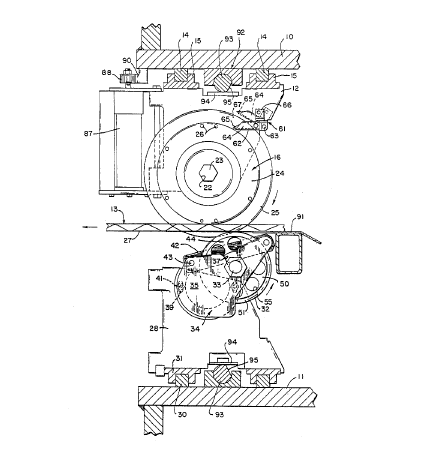
The main supporting framework =or the sl'_tting
apparatus of the aresent invention includes a horizon-
tal upper beam 10 and a parallel lower beam 11. The
3S beams l0 and ll extend across the width of the slitting
WO 91/13733 PGT/US91/01569
r y
_8_
;',.~
apparatus and are somewhat longer than the naxir.,u:"
width of a continuous moving web or sheet 13 oy corru-
gated paperboard or the like which moves between the '~
beams and the attached components of the slitting
apparatus to be hereinafter described. A plurality of
upper tool heads 12 are attached to the underside of
the upper beam 10 for individual movemen:. across the
width of the sheet 13 on a pair of linear ways 14
attached to the beam 10. Each upper tool head 12 has a
pair of linear bearing pads 15 attached to its upper
edge,..which bearing pans connect the tool head to the
linear ways 14 for positioning movement to set the tool
head in the position where a longitudinal slit in the
sheet 13 is desired.
A rotary tool holder 16 is attached to each
upper tool head 12. The~tool holder l6 includes an
inner hub 17 which fornns the inner race of a rotary
bearing 18. The outer race 20 of the rotary bearing 18
is secured in an annular boss 21 in the tool head 12.
The inner hub 17 of the tool halder 16 has' an axial
through bore 22 having a non-circular cross section,
such as the hexagonal shape si~own. The throucn bores
22 of the tool holders 16 mounted on the plurality of
tool heads 12 lie on a'common axis. A drive shaft 23
having a hexagonal cross sec~ion is mounted to e:.v.~nd
through the bores 22 in each ~.lurality of coaxialiy
mounted tool holders 16. T:~e crive waft 23 extends
across the full width of the apparatus and is connected
at one end to suitable drive means, whe=eby its driving ,
rotation causes tool holders 16 to rotate in bearincs
18 with respect to the tool neacs 12. Also, the drive ~~
shaft 23 provides support for the commo:.ly mounted tool
~.
holders 16 and tool heads :2 far movement along the
lin~a~ ways 14. Each tool hoide= to includes a:. outer
35' hub 24 to which a thin annular slitting blade 25 is
WO 91/13733 PGT/US91/01569
~~~~:1~
demountably attached, as with a series or machine
screws 26 disposed in a circular pattern. The blades
25 depend downwardly from their respective tool heads
such that the circular cutting edge extends below the
underside 27 of the corrugated paperboard sheet 13. .
A plurality of lower tool heads 28 are
supported for individual sliding movement along a pair
of lower linear ways 3U which are, in turn, attached to
the upper surface of the lower beam 11. Each lower
tool head 28 is supported for movement along the linear
ways 30 by a pair of bearing pads 31 similar to the
pads 15 on the upper tool heads 12. A pair of identi-
cal rollers 32 are coaxially mounted on each lower tool
head 28 for rotation on an axis parallel to the axis of
the upper drive shaft 23. The rollers 32 are mounted
with suitable bearings on a roller shaft 33 which is,
in turn, supported in a roller amounting. bracket 34.
The roller mounting bracket comprises a pair of
vertical side plates 35 interconnected at their lower
edges by a cross piece 36. mach of the side plates
includes an upwardly opening mounting slot 37 in its
.upper edge for receipt of the roller shaft 33. The
roller mounting bracket 34 is adjusta5ly attached to
one face of the lower tool head 28 by a pair of locking
screws 41. Vertical adjustment of the rollers 32 is
provided with a pair of diametrically opposite adjust-
ment sloLS 39 in the side plat. 35 adJacent the caller
mounting bracket 34. In this manner, the vertical
position o~ the rollers 32 may be varied at the tine o~ w
mach:.ne set-up to obtain accurate vertical position'_ng.
The roller mounting bracxet is locked .n position wits.
the ~.ocki. g screws 41 extend=ng trroug:~ the slot] 39
and into suitably tapped holes in the lower tool heat
28.
WO 91/13733 ., PCT/US91/01569
~' '.~y
;:~ y~~ '~' :'i '~ -10-
The rollers 32 are maintained axially spaced
on the roller shaft 33, as by the use of suitable
shins, to define therebetween an annular circumferen-
tial slot 44 having a width slightly greater than the
width of the blade 25. The roller mounting bracket 34
and attached rollers 32 are positioned to make tangent .
contact with the lower surface of the moving sheet 13
anc to allow a portion of the downwar3ly depending edge
of the blade 25 to be received in the circumferential
slot 44 between the rollers. The blade 25 is rotated
in a clockwise direction as viewed in Fig. 1 and the
moving sheet 13 is directed over the rollers 32 and
into the nip formed by the rollers and the blade in the
direction of rotation thereof, i.e. fram right to left
as viewed in Fig. 1. The drive shaft 23 is driven at a
speed sufficient to impart an edge speed to the blade
which is substantially greater than the linear speed
of the sheet. For example, the edge speed of the blade w
may be as much as three times the speed of the sheet or
20 greater. By utilizing a very thin blade, in the range
for example of .035 inches, and maintaining the cutting
~ edge thereof in a sharpened condition, the sheet 13 oz '
co=rugated paperboard or the like is provided witn a
virtually dust-free and extremely clean cut.
25 The rollers 32 are preferable substantially
smaller in diameter than the blade 25. The rollers may
have a diameter in the range of five to seven inches,
whereas the maximum diameter of the blade may be as
mucas approximately twelve inches. The axis of the
roller s.~aft 33 is affset horizontally in an upstrear"
direction frog the axis of the drive shaft 23 for the
blade 25. Preferably, the rollers 32 are positioned so
that th,e' line .af tangent contact between the rollers
and''the underside of the sheet 13 coincides with a line
nonaal to the Mane of the blade 25 and tangent to the f
WO 91!13733 PCT/U591/01569
-11-
-a..
~ ~ ~.j s ~3 ~:, ~~
blade edge. In this manner, the rollers provide
adequate support for the sheet against the downward
force of the rapidly rotating blade, resulting in the
characteristic clean cut.
As is best shown in Fig. 2, the rollers 32 in
one embodiment are machined or otherwise formed from
metal with large open annular recesses 53 on either
side of a central web 50. The central web SO inter
connects an outer cylindrical rim al and an inner hub
52, with the hub supported on bearings 54 for rotation
on the roller shaft 33. The circumferential slot 44
between adjacent rollers is defined by the axially
adjacent interior faces 45 thereof. In the Fig. 2
embodiment of the rollers, the width of the slot 44 is
defined by adjacent outer-radial edge portions 46 of
the cylindrical rims 51. The slot may have a naming!
width of approximately .045 inch. It is important that
the axially ad3acent interior faces of the rollers 32
define open interior portions, such as are provided by
the annular recesses 53. This allows paper scraps or
accumulated dust and the like to move radially inwardly
away from the slot 44 so as to prevent a build-up at -.
the slot/blade interface and possible jamming which
would adversely affect the quality of the slit. To
further prevent such a buila-up and jamming, the roller
mounting bracket 34 also supports a stripper bar 42
within the slot 44. The stripper bar is attached at
its ends beyond the outer surfaces of the rallars oy a
pair of mounting pins 43 extending between the side
plates 35 of the mounting bracket. Thus, the stripper
bar extends completely through the slot anc has an
upper edge disposed at an acute angle with raspect to
- the plane of the sheet and diverges therefran i:: the
downstream direction. The stripper bar 42 tencs to
prevent a build-up of accumulated dearis in the slat 44
WO 91/13733 PCT/US91/01569
..; '
r1 ,<!~ --12-
~~ a
and its inclined angle tenas to allow loose material to
be swept out of the slot. Ia addition, the central
webs 50 of the rollers 32 may be proviaed with a number
of circumferentially spaced openings 55 to allow
accumulated debris to be periodically removed from the
annular recesses 53.
The most severe wear on the rollers 32 occurs
at the axially adjacent radial edge portions 46
defining the slot 44. Aorasive wear from even small
amounts of board dust ana starca from the board
aahesive created during slitting causes an eventual
rounding of the edge portions 46 and eventually a
widening of the slot 44. Should the slot be worn to an
excessive width, shims between the bearings 54.may be
moved to the axial outer faces of the rollers and the
slot 44 returned to its original preferred width. It
should also be noted that the construction of the
rollers 32 of the Fig. 2 embodiment is such that they
are axially syzuaetrical and may, therefore, be reversed
to present new radial edge portions 46.
In Fig. 4, there is shown an alternate emboli-
ment of the rollers 32. In this embodiment, each
roller 56 comprises a substantially solic roller body
57, preferably constructed of a .tough plastic material
such as tdylatron or sltrahigh molecular weight poly-
ethylene. The axial interior .-'.aces 58 of the caller
bodies 57 are constructed to diverge in a radially
inward direction to define a slot 60 having its
narrowest width at the outer surf ace of the rollers
56, This is also to allow loose paper reaterial and the
like to move away from the racial outer edge of the
slot near the '_nterfacs with the moving Glade 25 and
into the more open interior. otherwise, the mounting
asse~ly and stripper bar utilized with the alternate
WO 91/13733 PCT%US91/01569
-13-
~~'~~~;~
rollers 56 is identical to the preferred embodiment
utilizing rollers 32.
Conventional corrugated paperboar~ is
typically fabricated with a starch-based glue which, in
prior art board slitting devices, has been found to
result in.a starch build-up on the cutting blades. In
the apparatus of the present invention, starch build-up
on the blade is even more critical because o= its
direct adverse effect on the normally extremely high
slit quality. In particular, the high speed at which
the slitting blades 25 of the present invention are
operated generates more heat which results in a f aster
build-up of starch. Eventually, the starch build-up
aay become great enough to result in extremely ragged
cuts and tearing or crushing of the cut edges such that
the clean razor slit characteristic of the present
invention is completely lost. To prevent a build-up of
. starch an the blade surfaces ad,acent 'the cutting
edges, a blade lubricator 61 provides a continuous thin
coating of a light lubricant to the blade while the
blade is in slitting operation. The blade lubricator
61 includes a generally U-shaped wick holder 62
pivotally attached at its closed end to the upper tool
head 12 by a mounting halt 63. The wick holder has a
pair of spaced, generally parallel lags 64 operatively
positioned to straddle the cutting edge of the blade
25. A piece of wick material is inserted in the wick
holder and secured to the inside faces of the legs
64. With the wick holder disposed in its operative
full line position shown in Fig. 1, the wick 65 is in w .
continuous contact with the blade surfaces adjacent the
cutting edge. Smal~ raeterea amounts of a light licuid
lsbricant, such as a thin penetrating oil, are supp~iea
to the wic)c holder and onto the wicx 6S by 'a posi~ive
displacem~ht injector 66 attached to the tool heat 12
WO 91/13733 PCT/US91/01569
-14-
.a ~-\ za
;; ~;' y1
r~ ~J
and receiving lubricant from a conmon source (not
shown). Only very small amounts of lubricant are
necessary to coat the blade edge witn a tnin layer that
prevents starch from sticking to the blade, thereby
precluding any starch build-up. For example, the
positive displacement injector 66 may provide about 0.2
cc of lubricant to the wick on timed pulses every eight
seconas. Obviously, the amount of starch available to
build-up on a blade is greatly dependent on the
'10 upstream gluing process and variations in the volume of
lubricant supplied and the timing of the infection
pulses may be suitably provided. To facilitate
changing or repositioning of the blade 25, the
lubricator 61 is pivotable about the mounting bolt 63
to an inoperative~~dashed line position shown in Fig. 1
in which the wick holder ~62 and attached wick 65 are
spaced radially beyond the blade edge.
Each of the slitting blades 25, as previously
indicated, may have a thickness of approximately .035
inch and is preferably made of a high quality steel.
The cutting edge 67 of the blade as shown in the
sectional view of the blade in Fig. 7 is provided with
a double bevel. The outer beve l at the cutting edge
may nave, for example, an included angle of 37°. In
order to maintain the high quality slit, the blade nust
not only be kept free from the buila-up of starch, but
the cutting edge must be maintained in a razor sharp
condition.
To maintain the necessary snare cutting edge,
the slitting apparatus includes a olade sharpener 68
adapted to sharpen one face of the outer blade edge
bevel while the blade is rotating . The blade sharaener
6~ is attached to an angled mounting bracket 7U mounted
by its vertical leg 71 to tha face of the upper tool
head 12 such that the horizontal leg 72 extends over
WO 91/13733 PCT/US91/01569
-15- N ~ ~ ~ ,'~, ~y r~
the upper edge of the blade 25. :~ rotary sharpening
tool 73 is attached to the horizontal leg 7= of the
mounting bracket and depends downwardly there=rom. The
sharpening tool includes a circular sharpening head 74
having a flat outer abrasive face 75. The head is
rotatably attached to a small air motor 76 attached to .
one end of a tool body 77 such that the abrasive face
75 is disposed at the saiae angle as the adjacent face
of the blade edge bevel. The tool body 77 is pivotally
attached at its end opposite the air motor to the
underside .of the horizontal ley 72 of the mounting
bracket 70. Specifically, the end of the tool body 77
is provided with a cylindrical recess 78 providing the
outer race for a ball bearing assembly 80, the inner
race of which is attached to the end of a stub shaf t 80
attached to and extending down from the mounting
bracket 70. A torsion spring 82 surrounds .the stub
shaft 8l with its ends in engagement with~ahe mounting
bracket and the tool body 77 to bias the latter to an
inoperative position in which the aarasive face 75 is
out of engage~aent with the blade edge. A small single
acting air' cylinder 83 is attached to the mounting
bracket 70 with the rod end 84 of the cylinder in
contact with the surface of the tool body 77. When
compressed air is supplied to the air cylinder inlet
fitting 85 fron an external source (not shown), the rod w
end~84 will be extended and tha tool body and attached
sharpening head 74 will be rotated aDOUt the stub shaft
81, against the bias of the tarsion spring 82, until
the abrasive face 75 makes light contact wyth the
beveled edge of the blade 25. air cylinder 83 operates
at very low pressure such that the abrasive face 75
makes light surface contact.witn the blade edge. The
air motor 76 which drives the rotary sharpening heat 74
is also supplied with corapresseo air via a f'oting 8u
WO 91/13733 .. ".= 1. PCT/US91/01569
~. ,: :..
,,
-1a- _
y'~ J
to drive the air motor whenever the tool bony is
rotated into operative sharpening position n,;
activation of the air cylinder 83. The air aotor 70
preferably operates at relatively high speed, for
example, about 5,000 rpm.
Under substantially continuous operating
conditions, if the blades 25 are made of a high quality
tool steel, it has been found that the blades need only
be sharpened a few times per week. The sharpena.rg tool
73 is operated so that the sharpening head 74 applies
only a very light force of not more than about three
pounds to the f ace of the bevel. Sharpening contact
need be maintained for only a short period of time to
remove approximately .001-.002 inch of material from
the blade edge. Periodically, the blade may be removed
from the tool holder 16. and reversed so that the
opposite face of the edge bevel may be sharpened to
maintain an overall balance in the cutting~eage of the
blade. ~ The slitting blades of the present invention
are tolerant to a substantial reduction in overall
blade diameter as a result of sharpening without
' adversely affecting the quality of the slit. Also,
little adjustment, if._any, of the blade position is
necessary over its useful life.
As indicated previously, in a typical slitter
apparatus, a plurality of upper tool heads 12 anc
slitting blades 25 are mounted on a common ,rive shaft
23 for individual movement and selective positionia7
along the linear ways 14 to provide a plurality oy
longitudinal slits in the advancing sheet 13 at an~~
selected positions across the wicth of the sheet. To
incividually position each upper tool neac i2, an
electric servomotor 87 is mounted on each tool head anc
drives a pinion gear 88 positioned to engage a linear
toothed rack 90 attached to the underside o~ the upper
WO 91/13733 PCT%US91/01569
-17- ~~~ i yr-y
beam 10, in a nahner well known in the art. It is also
known to utilize a similar motor-driven rack and pinion
assembly to position the lower tool hears 28. In
accordance with the present invention, however, it has
been found that both the upper and lower tool headsnaay
be simultaneously moved and repositioned with a single
upper servomotor 87 and its related gear 88 and rack 90
in a manner in which the overlapping portion of the
cutting blade 25 within the slot 44 between the rollers
32 (or 56) bears on the axial inner face of the roller
and carries the roller assembly and lower tool~head 28
along with the moving upper head assembly. In some
instances, however, it is recognized that the
blade/roller overlap, the strength of the blade
material, or the speed or thrust of the servomotor
assembly may be such that the bearing force between the,
blade edge and the rollers may break or otherwise
damage the blade. Thus, in Fig. 6, there is shown a
modified assembly in which the entire roller mounting
bracket 34 and attached rollers 32 may be pivoted
upwardly so that a much, larger portion of the blade
edge is received within the slot 44 to enhance the
bearing contact surface therebetween and distribute the
load imposed by repositioning over a greater portion of
the blade edge. Repositioning of the upper ann lower
tool heads is, of course, undertaken between board runs
and, therefore, at a time when there is no sheet
present to interfere with the substantial upward
movement of the rollers and roller mounting bracket
assembly.
As previously indicated, the rollers 32 (ar
56) support the advancing sneet at the point where the
slitting blade passes through the sheet. Supplemental
support ,of the sheet 13 is also preferably provided
just upstream of the rollers and slitting knife by an
WO 91/13733 ' ,."~ ;.'; ~ ;~ PCT/US91/01569 .-
i~l.~ ~ _18_
appropriate sheet suprorting surface 91, as shown in
Fig. 1. The continuous street 13 or web i3 otherwise
driven by appropriate weans external of the slitting '
apparatus, as is also well known in the art. As is
also known in the prior art, each of the plurality of
upper tool, heads 12 mounted on the common drive shaft
23 and linear ways 14 ar.e simultaneously locked in
their selected slitting positions with a common
lockdown apparatus 92. In the embodiment shown, the
lockdown apparatus comprises a long cylindrical cam
extending across the full width of the apparatus and
supported for rotation on its axis between a locking
.position with its cylindrical outer surface in locking
engagement with a locking pad 94 on each tool head and
an unlocked position in which an axial flat surf ace 9S
on the cam 93 is positioned directly adjacent and
spaced from the locking pad 94. In , the latter
position, the tool heads are unlocked for reposition
ing: Similarly, the rlurality of lower tool heaas 28
.are also locked in operating position with an identical
lockdown apparatus 92 including all components
identical- to those used for the upper looking
mechanism.
WO 91/13733 PCf/US91/Q1569
_lg_ ~~~~r7 D'.~
Various nodes. of carrying out the invention
are conteaplated as being within.the scope of the
following claims particularly pointing out and
distinctly claiming the subject caatter which is
regarded as the;invention ,