Note: Descriptions are shown in the official language in which they were submitted.
WO 91il4395 PCI`/US91/01853
. ,A
~ ,~ 7 ~
s
- GUIDEWIRE WITH FLEXIBLE DISTAL TIP
Description
. ' '
Technical Field
The present invention relates to a catheter
guidewire, and in particular, to a guidewire having a
flexible distal tip, and to a method of making the guide-
wire.
:~
Backqround ~af the Invention
Catheters are being used increasingly as a means
for delivering diagnostic or therapeutic agents to
internal target sites that can be accessed through the
circulatory system. Often the site which one wishes to
access by catheter is buried within a soft tissue, such as
brain or liver, and is only reached by a tortuous route
through small vessels or ducts--typically less than about
3 mm lumen diameter--in the tissue.
In one general method for accessing a deep-organ
target site alon~ a tortuous-path vessel, a torqueable
guide wire and catheter are directed as a unit from a body
access site to a tissue region containing a target`site.
The guide wire is bent at its distal end and may be guided
by alternately rotating ~nd advancing the wire along a
tortuous, small-vessel pathway, to the target site.
Typically the guide wire and catheter are advanced by
alternately advancing the wire along a region of the
pathway, then advancing the catheter axially over the
advanced wire portion.
:
: ~.', '',' ' ''' ',, ' "' : ', ' . :: '' , -
, '~ ~: ' , , . ' . ' , ' :
.. ' i , ,~ . ,
W091/1439~ ~ -2- PCT/US91~01853
Q ~
The difficulty in accessing such target body
regions is that the catheter and guidewire must be quite
flexible in order to follow the tortuous path into the
tissue~ and at the same time, stiff enough to allow the
distal end of the catheter to be manipula~ed from an
external access site, which may be as much as a ~eter or
more from the tissue site.
Heretofore, catheter guidewires for use in
guiding a catheter along a tortuous path have employed a
variable-flexibility construction in which the distal end
section of the wire is tapered along its length to allow
qreater flexlbility at the wire~s distal end region, where
the sharpest wire turns are encountered. The tapered ~-
section of the wire is encased in a wire coil, such as a
platinum coil, to increase the column strength of the
tapered wire section without significant loss of
flexibility in this region. Such guide wire constructions
are disclosed, for example, in U.S. Patents, No.
3,789,841, 4,545,390, and 4,619,274.
The tapered guidewire construction just
described is prepared, typically, by forming a fine-wire
coil, cutting the coil to a desired lengthr and fastening
the coil to the tapered distal end section of the
guidewire, typically by soldering. This method of
construction is relatively time consuming and costly in
manufacture. Furtherr the solder attachment of the coil
to the guidewire tip may crack during use, presenting the
danger of having the coil separate from the wire within a
vessel in the patient. Another limitation of the prior
art construction is that the distal end section of the
wire tends to kink on bending if the coil loses its
relatively tight pitchr e.g., by being irreversibly
stretched during lse.
, .,: '. . .. :, . - , ., . .: : :
,, ., ., . .. ~ ,^ .. ~ .; .
: ., ' ' ': ' ' ', ,' ' , : .", . ,, ,; " ' ' ., ',
.. . . .. . . .. . .
WO91/1439~ _3_ PCT/US91/01853
,; 2~77~
Disclosure of the Invention
~ .
It is a general object of the invention to
provide a guidewire which overcomes limitations or reduces
above-noted problems associated with prior art flexible
tip guidewires.
The guidewire of the invention includes an
- elongate wire having a proximal section and a flexible
distal end section which is at least about 3 cm long. The
distal end section is encased in an elongate polymeric
sleeve having, along the length of the sleeve, (a) a
continuous polymer expanse, and (b) axially spaced grooves
which are effective to increase the bending flexibility of
the sleeve and encased distal end section in substantially
any bending direction, over the bending flexibility in the
absence of the groove.
The sleeve may have inner and outer sleeve
portions formed of polymer materials having different
flexibilities, such as a low-density polyethylene or latex
forming the inner sleeve portion, and a Teflon~,
high-density polyethylene, or polyurethane forming the
outer sleeve portion. Alternatively, or in addition, the
polymer material forming the sleeve may have a relatively
greater flexibility progressing in a proximal-to-distal
direction.
The grooves or helical groove formed in the
cuter sleeve portion may be dimensioned to provide greater
flexibility on progressing toward the distal end of the
sleeve. This can be accomplished by increasing the radial
depth and/or the axial width of the groove(s) on
progressing toward the sleeve~s distal end.
In another aspect, the invention includes a
method of increasing the column strength in the tapered,
reduced- diameter distal end section of a catheter
guidewire. The method includes encasing the end section
in an elongate polymeric sleeve having, along the length
of the sleeve, (a) a continuous polymer expanse, and
. ~ :
,
:,: , . .: : -
,
WO91/14395 ~ J _4_ PCT/US91/01853
'; J `' ~
(b) axially spaced grooves which are effective to increase
the bending flexibility of the sleeve and encased distal
end section in substantially any bending direction, over
the bending flexibility in the absence of the groove.
Also disclosed is a ca~heter apparatus composed
of the guide wire and a thin-walled catheter designed to ~`
be advanced along the guidewire through a tortuous vessel
path, for positioning at a target site.
Brief DescriPtion of the Drawinqs .
Figure l shows a catheter apparatus, including a
flexible- tip guidewire constructed according to the
present invention; ~ ::
Figure 2 is an enlarged fragmentary distal-end
por~ion, shown partially in sectional view, of an
embodiment of the guidewire of the in~ention having a
helical groove formed in ~he outer sleeve portion of the
guidewire; ~.
Figure 3 illustrates how the grooves in the
outer sleeve portion of the guidewire, such as the Fig~re
3 guidewire, accommodate bending;
Figure 4 is a view like that in Figure 2, -~.
illustrating an emhodiment of the guidewire having formed
in the outer sleeve portion of the wire, a series of
axially spaced grooves whose depths increa~e on
progressing toward the distal end of the guidewire; ~ :
Figure 5 is a view like Figure 2, illustrating a :
guidewire embodiment with a coaxial-sleeve construction; :m
Figure 6 is a view like Figure 2, illustrating :~
an embodiment of the invention in which material forming
the sleeve in the guidewire has a single-step flexibiIity `:
gradient along its length; :~
Figure ' is a view like Figure 2, illustrating
an embodiment of the invention having a series of axially
35 spaced non-circumferential grooves formed in its outer ~:
sleeve portion; .
.
; ` ' ~ '
:
~, . " ., . ,, . , , , , , . , : . . ,
WO 91/14395 _5- ~ CTtUS91/0l853
Figure 8 is a view like Figure 2, illustrating
an embodiment of the invention in which grooves are formed
on the inner wall of the sleeve;
Figure 9 is a schematic view of a method of
producing a guidewire of the type illustrated in Figure 2;
Figure lO is a schematic view of a method of
- producing a guidewire of the type illustrated in Figure 4;
and
Figure 11 is a schematic view of a method of
producing an extruded polymer sleeve with an accordion
outer surface portion.
Detailed Description of the Invention
A. Guidewire Construction
Figure 1 shows a catheter device or apparatus 10
designed for accessing an internal target site in a body
along a tortuous vessel path. The device generally
includes a catheter 12 and a guidewire 14 constructed
20 according to the pre~ent invention, as detailed below. ;~
With continued reference to Figure 1, the cathe-
ter is composed of an elongate tubular member 16 having -~
proximal and distal ends 18, 20, respectively. The
tubular member is preferably between about 50-300 cm in
length, typically between about 100-200 cm in length. The
tubular member is preferably composed of a relatively
stiff proximal section, indicated at 22, which extends - ~ ~-
along a major portion of the catheter length, and one or ;~
more relatively flexibIe distal sections, such as section
24, which provide greater ability of the catheter to track
the guidewire through sharp bends and turns which may be ~ ;
encountered as the catheter is advanced along a tortuous ~ -~
path. The construction of a catheter ha~ing differential
- flexibility along its length is described in U.S. Patent
No. 4,739,768.
An inner lumen 26, indicated by the dashed
lines, extends between the two ends of the catheter. The
,. ... , . . ;
, ' ' '
.
WO91/14395 ~ 6- PCT/US91/01853
~ ,.
lumen may have a substantially uniform cross-sectional
area along its length, or may vary along the catheter
length, for example, in a distal end taper. It will be
appreciated that the tapered construction may require a
similar taper in the diameter of the guidewire, to
maintain suitable clearance between the guidewire and
catheter.
The catheter has an end fitting 28 through which
the guidewire is received, and through which fluid
material can be introduced into the catheter lumen. One
standard fitting which is suitable has an axially
extending port 30 through which the guidewire can be
received and rotated (torqued) and advanced or retracted
axially within the catheter, during a catheter placement
operation. An external port 34 may be used to deliver
fluid material through the catheter at the target site, ;
after removal of the guidewire.
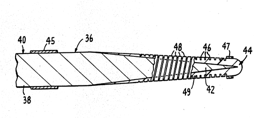
Figure 2 shows an enlarged, partially cross- -
sectional view of a distal end section of a guidewire 36
constructed accordin~ to one embodiment of the present
invention. The wire includes an elongate wire core 38
having a relativaly stiff proximal section 40 which
extends along a major portion of the guidewire, and a more -
flexible distal section 42 which is preferably tapered
along its length as shown.
The wire core is formed of a flexible,
torqueable wire filament material, such as stainless
steel, and has a total length typically between about ~
50-300 cm. The proximal section 40 preferably has a -~ :
30 unifo~m diameter thickness along its length of between `
about 8-30 mils (thousandths of an inch). The relatively . -
more flexible section extends along the distal 3-30 cm or `
more of the wire core. The taper in the core wire may be
continuous, as shown, or stepwise over one or more reduced
diameter steps. The minimum diameter of the core at its
distal end is preferably between about 1-5 mlls. ~` ! . '`' '
'`, ~'.-i.'
' , . ' ', `
.'' '`,~';
.
::
, :' .' , . ' .' .. :. . ' '` . ' '. , ,` ,' , " ' . . ' , ' ~ ~: . . ' ' ' : ,
.: ' ; , ' ' ' ! ' ' ` ' `
.. . . , '; .-. ,' , . :,,
.', ` ' `: ' " ' "' `' ~ ' .`. '` ' ' ` ' ' ` ` ' ' ', " ` ` . ' ," j ' , ' , ` . ' ' . . '
'"; ' ,' ' ""' `. ` '.`, ' ."' ' ''"'. ''' "". ' " "`' ' "','` :
WO91/14395 _7_ 2 ~ 7 7 PCT/U91/01853
In one embodiment, the dlstal end portion of the
wire core is coated with a gold or other radio-opaque
plating material, to allow this portion of the wire to be
visualized by fluoroscopy. The plating may be applied by
S electroplating, sputtering, or other metal plating
methods. The thickness of the plating is preferably
between about 0.2 to 0.5 mils.
The distal region of the wire core, i.e., at
least about a 3-cm distal end section of the core, is
encased in an elongate polymeric sleeve 44. The length of
the sleeve is preferably about 3-25 cm, and the wall
thickness is preferably between about 2-l0 mils.
The material forming the sleeve includes at
least an inner or outer sleeve portion which is relatively
non-elastic under axial compression or extension.
Preferred polymers include Teflon~, a high-density
polyolefin (e.g., polyethylene), or polyurethane which can
be bonded or otherwise tightly affixed to the core wire,
and which itself has a low-friction surface, as is the
case for Teflon~, or whose surface can be coated wi.th a
low-friction surface. Other suitable coatings include
virtually any polymer having exposed hydrogens, such as
polyester, polycarbonate, polyvinylchloride, latex or
silicone rubber, polystyrene, and a surface coating formed
of a highly hydrophilic, low-friction polymer such as
polyvinylpy.rrolidone,polyethyleneoxide, or
polyhydroxyethylmethacrylate or copolymers thereof.
The sleeve can be formed conventionally, such as `~
by extrusion, or molding, dip coating. In the former
30 case, the extruded sleeve can be attached to the wire core .~
by friction fit, adhesives, or heat-shrinkage. In the ~ :
case of a molded sleeve, the polymer material is ~
preferably molded directly on the distal end region of the -
wire core. The sleeve-encased portion of the wire may be
surface roughened, such as by chemical treatment, prior to
molding. Forming the sleeve by dip coating is done by :
.. , , : :, .;
. .
., : : . , -
W~91/14395 ~0`~ -8- PCT/US91/01853
successive dipping of the core distal region in a suitable
polymer solution, according to conventional methods of
polymer coat build-up. As will be seen below, the sleeve
may be composed of two or more different polymer materials
which differ in flexibility along either the axis or
radial dimension of the sle~ve.
With continued reference to Figure 2, sleeve 44
has a helical groove 46 (referred ~o hereinbelow as
axially spaced grooves or groove means) extending along a
major portion of its length. The grooves, which can be
formed according to the method described below with
reference to Figure 8, have a uniform depth and helical
pitch substantially along the length of the sleeve. The
depth of the grooves is preferably at least about 50
percent of the a~erage radial dimension of the sIeeve.
The pitch of the groove is preferably about 5-50 mils.
The width of the grooves is preferably about 10-40~ of the
width of the pitch, e.g., 2-10 mils. The grooves in the
sleeve form helical strands or windings 48 which are
formed integrally with and encircle an inner portion 49 of
the sleeve. In the embodiment shown in Figure 2, the
groove is formed by cutting with a blade, as described in
Section B below.
The g1~idewire is provided with a pair of
radio-opaque bands 45, 47 located adjacent opposite ends
of the sleeve, as shown, for use in visualizing the
guidewire fluoroscopically (if the distal section of the
wire core is not plated with a raclio-opaque material). ~
The sleeve portion of the bands is formed of gold, -
platinum or the like and clamped to the guidewire.
Figure 3 shows the distal end region of the
Figure 2 wire in a bent configuration, illustrating how
the helical groov~s in the sleeve contribute to greater
flexibility in the distal end of the guidewire. It is
known that the force required for bending a tube is
related to the wall thickness of the ~ube, the tube's
. ', , ',
.. , : ': , : , . : ~ : . -
.. , . . , - - , .
. . . :: . ~:. :... . . . . .
" , .. . . . . .. ..
,.:. :: :.: ;, , . ,, . :
,, , , . , :, . . . , .. : .
.. ,, ', .,,,. . , , ,' ',' , ,~ ~, ,
,. ,. , ~ ,
WO9l/l4395 _9_ ~ ~rlrl~i 8 PCT/U~91/018~3
outer diameter, and the bending modulus of the material
forming the tube. In the present case, the helical
windings in the outer portion of the sleeve effectively
reduce the outer diameter of the outer portion of the
sleeve by the depth of the groove, typically greater than
half the sleeve wall thickness. This substantially
- reduces the effective bending modulus of the material (by
reducing the thickness of the wall which undergoes bend-
ing). On the inner side of the arc, the windings can
accommodate bending by a slight radial displacement, as
indicated, also reducing the effective bending modulus by
reducing the radius of the inner wall of the tube.
Also as seen in Figure 3, when the guidewire is
in a bent condition, the helical windings on the inner
side of the bending arc are brought into contact with one
another, and at a suf f icient bending angle, become ~`~
compressed against one another. This contact and
compression increases the effective cross sectional
thickness and resistance to axial compression in the
guidewire, thus incrPasing the column strength of the
guidewire in the region of the bend.
Also, the radial sliding movement of the -
windings under compression, noted above, relieves
localized compression in the region of the turn, and thus ~ :
reduces the tendency of the wire to buckle under axial
compression in a region of sharp turn.
Figure 4 shows an enlarged, partially cross
sectional view of the distal end region of a guidewire 50
constructed according to another embodiment of the
invention. The wire core and polymer sleeve forming the
distal end portion of the guidewire are indicated at 52, ;
54, respectively. The invention differs from the Figure 2
embodiment in two respects. First, the sleeve, when
placed on the tapered portion of the wire core, has a
substantially uniform diametex along its length,
corresponding approximately ~o the outer diameter of the
. ~ ~ ~; .: : :, . , : . . .
. " . ,~ '. .,.., .' . . ;: . ~.
:: .: .' . ~ :
. . .
WO~1/1439s ''J -10- PCT/US91/01853
core wire. The sleeve can be formed, for example, by
molding the sleeve on the tapered end section of the wire
core, or by dip coating to produce progressively greater
sleeve thic~ness on progressing toward the distal end of
the sleeve.
Secondly, the groove means in the sleeve
includes a plurality of axially spaced circumferential
grooves, such as grooves 56 extending through an outer
portion 58 of the sleeve, with increasing groove depth on
progressing toward the distal end of the sleeve. As seen,
the depth of the grooves is such as to define a
substantially uniform-thickness inner portion 60 extending
along the length of the sleeve, in contact with the
tapered portion of the core. The depth of the grooves
increases from about 10~ to about 80~ of the radial
thickness of the sleeve, on progressing distally. The
axial spacing between grooves is similar to the pitch of -
the helical groove in the Figure 2 embodiment.
The grooves form a plurality of axially spaced ;
rings, such as rings 62, with uniform outer diameters and
decreasing inner diameters progressing distally along the ~ ~ `
sleeve. The grooves may be formed, for example, by the ~ ;
method described below with reference to Figure 10. The -
functioning of the rings to produce flexibility along the
length of the distal portion of the guidewire, and reduce
the tendency of the wire to buckle is substantially as ::,
described with reference to Figure 3. In particular, the :
relatively deeper grooves in the sleeve in the distal
direction provide a small, substantially uniform effective
wall thickness along the outer arc of the entire sleeve
length on bending.
It will be appreciated that the guidewire
construction shown in Figure 4 provides greater column
strength than the Figure 2 construction on bending, due to
the greater effective thickness of the sleeve in a bent
condition in which the rings of the sleeve are in contact
.. , . : . :. . : .: ."
,, .. ::. : . .
.~ . . .
, ., . , , , , ;
, :. . : , , : ~ ~ .
: ~ ,: . :. , . : .
. :..... . ::, : .
, .: . :., : ..
WO 91/14395 ~ .'' & PCI~US91tO1853
~ :, .*;
and are compressed against one another along the inner arc
of the tuxn.
Guidewire 50, as well as th0 guidewires
illustrated in Figures 5-7, are provided with radio-opaque
bands, such as bands 55, 57 shown in Figure 4.
Figure 5 shows an embodiment of a guidewire 64
constructed according to a third embodiment of the
invention. Guidewire 64 differs ~rom guidewire 36 shown
in Figure 2 in that the sleeve, here indicated at 66, is
composed of an inner, elastomeric tube 68, and an outer,
relatively non-elastic tube 70 encasing the inner tube.
The two tubes may be formed togsther by fusing them
chemically or by heat, by an adhesive, or by heat
shrinking the outer tube over the inner one. Typically
the inner tube is formed of latex or other flexible
elastomer, and the outer tube, of polypropylene,
high-density polyethylene, or Teflon~. ~
The groove means formed in sleeve 66 includes ~ ;
axially spaced circumferential grooves 72 which extend
through outer tube 70 only. Preferably the width of the
grooves is sufficiently small, e.g., less than about a
mil, so that the rings formed by the grooves in the outer
portion of the sleeve are in contact with one another in -
the straight condition of the wire.
The column flexibility of the distal end portion
of the wire is provided by the elastomeric inner sleeve
portion, which allows the relatively incompressible rings
formed in the outer slseve portion to spread apart in the
outer arc of a bend. That is, the resistance to bending
contributed by the sleeve is the resistance of the
elastomeric sleeve itself to bending plus the distortion ~ -
in the elastomeric sleeve produced by the spreading apart
of the rings in ths outer arc of the bend. It can be
appreciated that this resistance can be made quite small.
At the same time, the stacking of the rings
against one another, either in a straight- or bent-wire
W09l/l4395 ~ 12- PCT/VS91/~18S3
confi~ù~ation adds significantly to the column strength of
the wire's distal end region, since compressing the rings
in an axial direction requires an axial distortion along
the entire length of the sleeve.
Another embodimen~ of the invention is shown at
74 in Figure 6. Here the guidewire sleeve, indicated at
76, is composed of a proximal sleeve section 78 formed of '
a polymer having a selected flexibility, and a distal
sleeve section 79 formed of a more flexible polymer
material. By way of example, the proximal and distal
sections may be formed of high- and low-density poly- ~
ethylene, respectively. ~ -
The groove means formed in sleeve 76 includes a
series of axial grooves, such as grooves 80 in the
15 proximal sleeve section, and grooves 82 formed in the ;~
distal sleeve section. As seen, the latter grooves have
increasing axial widths on progressing dis~ally, allowing ~ -
increasing flexibility through this section of the guide- -~
wire. This feature is gained at the expense of reduced
column strength in the distal section, since the rings
formed by the grooves do not support column compression
except when the guidewire is bent to bring the rings into
contact at the inner arc of the bend. This embodiment ~ -
further illustrates the ability to selectively vary flexi-
25 bility and column s~rength properties along the length of `~
the distal region of the guidewire by varying (a) flexibi-
lity of the material forming the sleeve, (b) thickness of
the sleeve, and (c) depth and width of th~a grooves formed
in the sleeve.
Figure 7 shows a guidewire 84 formed in
accordance with another embodiment of the invention, and
composed of a wire-core 86 and a sleeve 88. The groove
means in the sleeve includes a plurality of axially spaced
grooves, such as grooves 90, which (a) extend about only a ;~-;
portion of the sleeve cir~umference, (b) are axially
misaligned, so that the circumference of the sleeve is not
~. : : . . . . - : .:. ~ ::
: -
.
WO91/l439~ -13~ l J ~ .;F~VS91/01853
continuously cut at any axial location, and (c) extend a
selected depth through the sleeve, and may be through the
entire thickness of the sleeve.
The grooves in the guidewire increase the flexi-
bility of the distal end region for the reasons discussed.
At the same time, the continuity of sleeve material in an
axial direction, which substantially prevents stretching
or compression of the sleeve, adds column strength to the
wire core.
Yet another embodiment of the invention is shown
at 92 in Figure 8. A sleeve 94 in this embodiment has
inner-surfacegrooves, such as grooves 96, forming a series
of inner, axially spaced rinss, such as rings 97, which
are attached to the wire core, indicated at 98, as by
adhesives. The sleeve may be prepared for example by
forming an extruded tube about a threaded mandrel, and
'unwinding" the mandrel from the tube after hardening.
When the sleeve portion of the guide wire is
bent, the inner rings of the sleeve accommodate bending by
localized deformation due to compression or stretching in
a radial direction. This has the effect of reducing the
effective bending modulus of the sleeve by reducing the
thickness of the sleeve which undergoes bending. At the
same time, the ungrooved outer po:rtion of the sleeve
25 contributes to the column strength of the wire in both a ~ ~
straight or bent-wire configuration. ~ :
In e~ch of the guidewires described above, the
polymer sleeve encasing the wire core includes a sleeve
which has (a) a continuous or unbroken polymer expanse,
30 and (b) axially spaced grooves which ~re effective to -~
increase the bending flexibility of the sleeve. The ;
continuous polymer expanse in the Figure 2-6 embodiments
is the inner, unsrooved sleeve portion which forms a
continuous expanse in contact with the wire core; in the ~'
Figure 7 embodiment, the ungrooved portion of the sleeve;
. ....
WO91~1~39~ 14- PCT/VS91/01853
and in the Figure 8 embodiment, the outer, ungrooved
portion of the sleeve.
In each embodiment, the continuous polymer
expanse provides a relatively incompressible expanse
5 effective to increase the column strength of the encased ~`
distal end portion of the wire core (Figures 2, 4, and
6-8), or a flexible substrate on which a relatively
incompressible grooved portion of the sleeve i5 mounted,
for producing the requisite column strength (Figure 5).
B. Guidewire Method '- -
In another aspect the invention includes a ;~ !
method of increasing the column strength in the tapered, ~ ~`
reduced diameter distal end section of a catheter guide-
wire wire core. The method includes encasing the distal
end section of the core in a polymeric sleeve having (a) a
substantially continuous planar expanse along its length,
and (b) axially spaced grooves disposed along the length
of the sleeve for increasing the bending flexibility of
20 the sleeve and encased distal end section in substantially ~
any bending direction, substantially along the length of ~ -
the sleeve, over the bending flexibility in the absence of ~-~
the grooves.
A variety o~ polymer sleeves suitable for use in
practicing the invention have been described in Section A
above. The sleeve may be secured to a wire core~s distal
end region by adhesives, heat shrinking the slee~e on the
wire core, or by chemical bonding to a chemically treated ~-
core coated surface. Alternatively, the sleeve may be ;
formed on the wire core by dip coating.
The grooves in the sleeve may be formed before
or after attachment of the sleeve to the core wire. In a
generally preferred method, the sleeve is attached to the
core prior to grooving the sleeve.
Figure 9 illustrates, in schematic view, a
method for forming a helical groove in a sleeve lO0 ~ ;
,, - ,. ,:, - , ~ , : - ~ . , .
:,, , ,:; . : '............... , '
,', '' .' ' ' . ' ' ' ' '., :' ': '
WO91/14395 -15~ 7 !~ PCT/US9t/01853
encasing a wire core 102. ~ machine having a pair of
motor-driven chucks which are (a) rotated synchronously,
and (b) biased under tension away from one another (in the
direction of arrows 105, 107) is suitable for use in the
Figure 9 method. The opposite ends of the distal end
section of the wire core are supported in the chucks,
under tension, and the chuclcs arerotated at a selected
rotational speed, preferably between about 10 and 50 rpm.
The direction of rotation is indicated by arrow 106 in the
figure.
The sleeve is grooved by a blade 108 which can
be positioned (in the direction of arrow 112) a selected
distance from the guidewire to a desired depth of cut in ~;
the sleeve~ The blade, which is also referred to as a
cutting tool, is mounted on a carriage 114 for shifting at
a selected speed along the axis of the guidewire, as the
wire is rotated. The speed of shifting (in the direction
of arrow 116) is adjusted to achieve a desired helical
pitch in the sleeve. The method of forming a helical
groove in a sleeve is suitable for forming the guidewire
illustrated in Figure 2.
If a sleeve 119 with an outer portion having
axially spaced circumferential grooves of constant depth `~
formed in the sleeve, a cutting configuration like that
shown in Figure 10 can be used. The distal end section of
a guide wire is supported in synchronously rotating
chucks, as described above. A multiple-blade cutting tool
118 having a plurality of blades, such as blades 120, is
mounted adjacent the rotating guidewire for shifting in
the direction of arrow 122 to a selected cutting depth in
the guide wire sleeve. The cutting tool is preferably
moved toward the rotating wire incrementally, such that
the maximum groove depth is reached only after several
guidewire revolutions. The spacing between adjacent
blades is adjusted to produce a desired spacing between
adjacent grooves in the sleeve.
. :,: , : , . .: , : . .
. . , ~ ,.
", ~ , , . . ~ ,
:.... . .. . .. .
W091/l4395 ~` -16~ PCT/US91/01853
c~,~................. ..' ~ ' '.
A method of forming an outer sleeve portion
having a bellows-like construction is illustrated in `
Figure 11. The figure shows the extrusion tip 126 of a
polymer-tube extrusion device 128 having an annulus 130
through which polymer material is extruded ln molten form.
The tip is modified, in accordance with the present ~-
application, to include an oscillatory element 132 which
oscillates in the direction of arrow 134 as the polymer
material is extruded. This oscillation causes extruded
material to be alternately and repeatedly comprassed and
extended, forming the accordion-like surface feature of
the tube which is indicated in the figure. After the tube
is formed, it is cut into sections and attached ~o a
guidewire core, e.g., by heat shrinking. ~-
From the foregoing it can be seen how the
various objectives of the present invention can be met.
The polymeric expanse in the sleeve is effective to give
the tapered wire core region of the guidewire added column -~
strength for advancing the wire through a tortuous path
vessel region. When the sleeve is bent, compression of
the rings or windings in the sleeve provides continued
column strength. -
The grooves in the sleeve significantly reduce
the bending force required to form sharp bends in the
distal region of the wire, by (a) effectively reducing the
outer diameter of the sleeve on the outer arc of the turn,
and (b) accommodating compression on the inner arc of the
turn by radial sliding movement. The tendency of the
guidewire to buckle in a region of sharp turn is also
reduced by the shifting the windings or turns in the inner
arc of the turn to reduce localized compression in the
sleeve.
The guidewire can be readily formed from
inexpensive polymer tube materials, and the composition of
the polymer and groove pattern, depth, and axial width can
be selected to achieve desired bending and column strength
:; . . . ....... . - ~ . ,,: . ~ ~ ,
: , , . :
, . ,
,
WO~1/143~5 -17- ,'~ J~ (3P~T/us9l/ol853
properties along the length of the sleeve portion of the
guidewire.
The distal end region of the guidewire can be
adapted readily for visualization, e.g., in a fluoroscopic
procedure, by radio-opaque bands adjacent opposite ends of
the guidewire sleeve.
.~,
- ;
~ ' '
.
''-~
,
~` -
~' , ;
'~ '''~,,'.
.-. . ., , ;' ': , ' . , . ' ~ ~ :
.. ~' ,,:, ,,
,''' ' ' , ' ,. ,,'~, ', ~ '
,. ' , . , ' '