Note: Descriptions are shown in the official language in which they were submitted.
CA 02077871 1999-03-19
A FOIL AS A COVRRTNG FOR AN IMPRESSION CYLTNn~R IN
ROTARY OFFSET PERFECTING PRESSES
The invention relates to a foil as a covering for an
impression cylinder of a rotary offset perfecting press.
Such a foil is known from the European Patent EP 0 017 776.
Accordingly, nickel, chromium-nickel-steel, or a plastic
material of high elasticity have been used as a backing
layer, and a chromium coating is applied to this backing
layer for evening out the microroughness. The backing
layer has a surface known from German Patent DE 24 46 188,
which comprises statistically uniform but irregularly
distributed convex and concave structural elements, said
concave structural elements being formed as spherical
calottes, so that a sheet is supported by the poles of
these spherical calottes. With such a foil applied to an
impression cylinder, frequently called anti-smudge foil,
the ink transfer behavior of the outer cylindrical surface
of the sheet-guiding impression cylinder is markedly
improved as compared with the known prior developments.
The foil not only prevents the occurrence of smudging in
face printing after sheet reversal, but it also improves
the print quality of backside printing. In connection with
the material of the backing layer, this improvement has
mainly been attributed to the structure of the sheet-
supporting surfaces as spherical calottes, because the
spherical form facilitates the transfer of accepted ink.
The chrome-plating of the foil results in good ink transfer
CA 0207787l l999-03-l9
2 --
behavior already in the start-up phase and can be washed
easier than the formerly somewhat rougher backing layer.
The very hard chromium layer prolongs the durability of the
sheet-guiding foil, so that a good ink transfer behavior of
5 the foil is practically maintained beyond its life time.
Other disclosures of improvement of the ink transfer
behavior of an impression cylinder in a rotary offset
perfecting press could not achieve the results obtained
with the foil according to European Patent EP 0 017 776 Bl.
From German Patent DE 28 20 549 Al it is known to apply a
thin nickel layer with a hard-nickel-coating to the
sandblasted surface of a backing layer consisting of
aluminium or copper. According to DE 12 58 873, there is
15 applied a chromium layer in place of the nickel layer.
However, this does not have the improving effect on the ink
transfer behavior as could be reached with the foil
according to EP 0 017 776.
From a pamphlet issued by Minnesota Mining & Manufacturing
Co. GmbH, Dusseldorf, Germany, there is known a cover sheet
for the impression cylinder of a web-fed printing press,
which consists of a strong hemp-fiber packing having a
coating of synthetic resin mixed with a powder of
25 microscopically tiny glass pellets. With this arrangement
another attempt is made in face printing and backside
printing of webs to attain results with a surface structure
of spherical calottes which come close to the results
achieved with a foil according to EP 0 017 776 Bl.
From the French Patent FR-A 2 283 995 there is known a
sheet-guiding foil, consisting of nickel, as a covering for
the impression cylinder of a rotary offset perfecting
press, the one surface of said covering being smooth and
35 the opposite surface thereof being provided with
statistically uniformly distributed spherical calottes of
equal height. This metal foil is made according to the
method of galvanoplastic molding with the aid of a
W
.
CA 02077871 1999-03-19
...._
negative-mold consisting of nickel. The first ones of the
foils formed in such a negative-mold are relatively smooth.
However, the more foils are formed, the stronger is the
microroughness appearing on the structured surface. On the
other hand, it was observed that such foils showed a
reduced ink transfer behavior after being used in the
start-up phase. Only after longer use of the foil in the
machine the optimal ink transfer behavior was reached.
It is the object of the invention to improve the print-
technical properties of a foil with respect to quality
improvement of the printing result in perfecting,
particularly in multi-color printing and in printing with a
low screen count, while maintaining all the known
advantages.
The foil, according to the present invention, has a
structural surface statistically uniformly distributed
convex and concave structural elements thereon. A
microroughness reducing chromium layer disposed on the
rigid support layer and forming a sheet guiding outer
surface of an impression cylinder. The convex structural
elements have curved upper support surface supports by
upwardly tapering, steeply inclined side walls which merge
with the concave structural elements. This arrangement
reduces the spacing between convex structural elements.
Thereby, the ink transfer behavior is benefitted to a
degree that a quality improvement of the print is clearly
noticeable, especially on dull-finish papers, thin papers,
and in the case of low screen counts in the range 80 to 100
lines per cm. The new structure of the foil provides
narrower spaces between sheet-supporting points while the
pressure area remains unchanged, so that the specific
pressure per point is reduced. By grinding the foil on its
backside, very precise thicknesses with a minimal tolerance
range can be achieved, so that the foil also is suitable
CA 02077871 1999-03-19
..._
for double-size impression cylinders in perfecting presses
without a drying facility.
A clearly perceptible increase in quality of the printed
image in perfecting and with eight-color printing presses
in a 4/4 operation - which are much in demand nowadays -
can be achieved after sheet reversal in connection with a
collective fine-adjustment of the pressure in the printing
nip through an electronic computer control system,
depending on paper quality and print forme.
The shape of the tops of the egg-like convex structural
elements which are all of the same height, allows close
placement of the convex structural elements, thereby
effecting a precise and differentiated ink transfer
behavior. It is advantageous that the support points can
be arranged in greater density than before, so that they
are situated closer to each other than the spherical
calottes and that, while the same pressure area is
provided, less area pressure can be worked with.
A special embodiment of the features of this invention,
therefore, provides that the convex elements of the
calotte-type structure, in optical enlargement, have the
shape of the top of an egg.
At any rate, the known and utilized advantages of foils
consisting of a backing layer, for example, of nickel and a
chromium coating, are maintained, particularly the
possibility of replacement of the foil, so that there can
take place an advance adjustment to the quality of the
printing paper and to the print forme through the selection
of a foil with a different thickness or a different
structure of naps. Also, the option of replacing a
conventional foil is maintained, for example, replacement
of the foil for carrying out printing orders based on a
different screen count, like up to 120 lines per cm.
.
CA 0207787l l999-03-l9
__ -- 5
The structurally suitable foil for a printing order can be
applied quickly and most effective by means of an automatic
foil replacement device.
5 The making of the mold for the galvanic molding of the
surface structure or foil according to the invention can
take place by applying galvanic techniques, or etching, or
through laser-type engraving. The method of producing the
foil will not be influenced by the features of this
invention.
The present invention will be best understood from the
following description of specific embodiments when read in
15 connection with the accompanying drawings, in which:
Fig. 1 is cross-section on an enlarged scale of an ink-
carrying foil according to the invention;
20 Fig. 2 iS a cross-section of the ink-carrying foil
according to Fig. 1 and of the foil without
carrying ink according to the invention.
Fig. 3 is a plan view of a section of the foil
according to Fig. 2 with a structured surface;
and
Fig. 4 is a schematic view showing the arrangement of
the foil on the impression cylinder of a rotary
offset perfecting press on a more reduced scale
than that of the foregoing figures.
The foil 1 guiding or carrying a sheet on the circumference
of an impression cylinder of a printing press consists of
nickel, chromium-nickel-steel, or plastic material. The
foil has a thickness of approximately 0.2 to 0.4 mm. The
surface of the foil 1 is composed of statistically
uniformly distributed convex and concave structural
.
CA 02077871 1999-03-19
elements, with the convex structural elements 2 being
formed as domes, the poles of which being at the same
height. The sheets on the impression cylinder are
supported by these poles of the domes 2. The height of the
dome 2 with respect to the concave structure amounts to
approximately 0.03 to 0.04 mm. In Fig. 1, in the left-hand
part of the drawing, the ink separation is symbolically
illustrated while the sheet is lifted off from a dome 2.
The circles 3 drawn in Fig. 1 illustrate the form of the
spherical calottes of known developments, in order to point
out the differences of the structure according to the
invention as opposed to the state of the art. The convex
structural elements 2 according to the invention allow more
space for receiving ink than the known spherical calottes.
This advantageous space distribution also facilitates the
removal of ink deposits, which means that the latter can be
washed from the foil easier and faster.
Fig. 2 shows the same foil 1, however without ink. The
convex structural elements 2 have an oval shape, with the
radius of curvature from the pole 4 to the passage 5 into
the concave structural elements 6 becoming gradually
larger. This takes on the shape of an egg 7 in the
respective exemplary embodiment, as indicated in Fig. 2 in
optical enlargement only for illustration, especially the
shape of a hen's egg, the size of which being defined by
the top of the pole 4 and the backside 8 of the foil.
Consequently, the radius of curvature of the convex
structural elements 2 which are defined by the egg top
becomes gradually larger from pole 4 to passage 5 into the
concave structural elements 6.
In this arrangement, too, the tops of the poles 4 of the
convex structural elements 2 have the same height. The
structural elements 2 are statistically rather uniformly
distributed in known manner, even though they are
irregularly arranged. In the preferred embodiment the
convex structural elements 2 change over directly into the
CA 02077871 1999-03-19
._
concave structural elements 6, so that the convex
structural elements 2 are closer to each other than in the
known arrangement according to Fig. 1. The relatively
narrow-spaced arrangement of the convex structural elements
resulting therefrom is illustrated in Fig. 3. In departing
from the present concept that a spherical form of the
structural elements facilitates the ink separation while
the sheet is lifted off from the impression cylinder, it
has been found out that the inventive oval form with the
curvature radius towards the pole tops of the convex
structural elements gradually becoming smaller results in
an essential improvement in ink separation and thereby in a
perceptible improvement in print quality. Through the
smaller support surface provided by the domes 2, as opposed
to the spherical calottes, the ink feed is reduced, so that
the successive sheet has less ink to take away. Thereby,
the ink transport can become more stable.
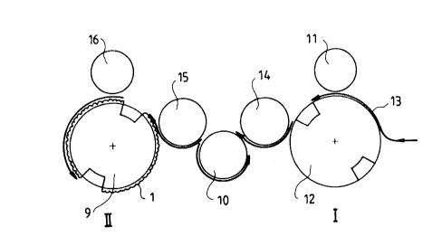
In Fig. 4 the arrangement of a foil 1 is shown on a double-
size impression cylinder 9 of a rotary offset perfecting
press after sheet reversal through cylinders 10 and 15, as
described above. The sheet 13, having been face-printed in
the nip between the blanket cylinder 11 and a double-size
impression cylinder 12, is fed to the storage cylinder 10
by the transport cylinder 14 and then turned by the
perfecting cylinder 15 to enter the nip between the blanket
cylinder 16 and the impression cylinder 9 for backside
printing.