Note: Descriptions are shown in the official language in which they were submitted.
,.~ ,r ~~."..j ~.~ ~~~ ' 1
~.~'..~ ; I ~..,.i w
SPECIFICATION
TITLE OF THE INVENTION Disc Cartridge Having Mistaken
Recording .inhibiting Mechanism
BACKGROUND OF THE INVENTION
Field of the Invention
This invention relates to a mistaken recording inhibiting
mechanism for a disc cartridge accommodating a disc capable of
re-recording information signals, such as a magneto-optical disc.
Description of the Prior Art
There has hitherto been used a disc, such as a magnetic disc
or a magneto-optical disc, in which information signals once
recorded thereon may be erased to permit recording of new
information signals.
A disc cartridge accommodating a disc of this type is
provided with a mistaken recording inhibiting mechanism for
preventing mistaken erasure of information signals once recorded
on the disc.
It is possible with the mistaken recording inhibiting
mechanism to make a selection between the state permitting re-
recording of the information signals and the state inhibiting
erasure of the information signals once recorded on the disc.
Fig.1 shows a typical arrangement of a mistaken recording
inhibiting mechanism for a disc cartridge which is adapted for _.
making a selection between the re-recordable state and the
mistaken recording inhibiting state.
1
w?~~r~,. or,~~ s;,.-
W ~.. 9 a ...f ;'r a
The mistaken recording inhibiting mechanism includes
mistaken recording inhibiting member 3 which is movably mounted
on a lower half 1 of the cartridge main body for opening or
closing a detection hole 2 bored at a corner of the lower half
1.
The mistaken recording inhibiting member 3 is formed by
molding synthetic resin and has a closure web 4 of a size large
enough to.close the detecting hole 2 bored in the lower half 1
and first and second resilient arms 5, 6 extended from both ends
of the closure web 4 for facing each other.
A slide guide T for guiding the sliding direction of the
mistaken recording inhibiting member 3 is formed upright on the
inner surface of the lower half 1. This slide guide 7 is formed
substantially parallel to an upright peripheral wall B of the
lower half 1 constituting the outer wall on the rear side of the
cartridge main body.
The surface ~of the slide guide 7 opposite to the upright
peripheral wall 8 is formed with first and second engaging
recesses 10, 11 adapted for being engaged in a retention bead 9
formed on an outer lateral surface of the distal end of one of
the resilient arms 5 of the mistaken recording inhibiting member
3. These first and second engaging recesses 10, 11 are formed
at such positions that the retention beads 9 may be engaged with
the rib 9 when the mistaken recording inhibiting member 3 has
been moved to a position of closing and opening the detecting
2
~.,~ ' a
l~.o '~.., a J ~ , ) r
hole 2, respectively.
The upright peripheral wall 8 formed as one with the lower
half 1 is formed with an opening 13 for exposing a movement
actuating member 12 formed on the outer lateral surface on the
distal end of the other resilient arm 6 of the mistaken recording
inhibiting member 3 to outside of the cartridge main body. The
opening 13 is of such an extent as to permit the mistaken
recording.inhibiting member 3 to be moved between a position of
closing the detection hole 2 and the position of opening the
detection hole 2.
A barrier wall 14 is formed upright within the lower half
1 for facing the opening 13.
Referring to Fig.2, the mistaken recording inhibiting member
3 is arranged within ,the lower half 1, with the closure web 4
positioned facing tie detecting hole 2 and with the resilient
arms 5, 7 extending between the slide guide 7 and the upstanding
peripheral wall 8.~
Meanwhile, a width Wl between the resilient arms 5 and 6 is
selected to be wider than a distance Wz between the slide guide
7 and the upstanding peripheral wall 8, so that, when the
resilient arms 5, 6 are extended between the slide guide 7 and
the upstanding peripheral wall 8, the resilient arms 5, 6 are
resiliently deflected in a direction approaching towards each
other for being pressed against the slide guide 7 and the
upstanding peripheral wall 8.
3
,~w ~r~..-a,~ p °?
l~.rl .i.. : ~ ~...~ L.9 ~a
The movement actuating member 12 formed on the other
resilient arm 6 of the mistaken recording inhibiting member 3
provided within the lower half 1 ins exposed to outside the
cartridge main body.
By acting on and sliding the movement actuating member 12
formed on the other resilient arm 6 exposed to outside of the
cartridge main body via opening 13, the mistaken recording
inhibiting member 3 mounted within the lower half 1 is slid in
a direction shown by an arrow A and an arrow B in Fig.2, with the
resilient arms 5, 6 being guided by the slide guide 7 and the
upstanding peripheral wall 8.
When the closure web 4 of the mistaken recording inhibiting
member 3 is at the position of closing the detecting hole 2, as
shown in Fig.2, the retention bead 9 on the resilient arm 5 is
engaged in the first engaging recess 10 for maintaining the
detecting hole 2 in the closed state. iNhen the mistaken
recording inhibiting member 3 is.slid in the direction shown by
an arrow A in Fig.2 until the closure web 4 reaches the position
of opening the detecting hole 2, the retention bead 9 is engaged
with the second engaging recess 11 , as shown in Fig.3, for
maintaining the detecting hole 2 in the opened state.
Meanwhile, the mistaken recording inhibiting member 3 of the
mistaken recording inhibiting mechanism is supported by the lower
half 1 by having the resilient arms 5, 6 resiliently deflected
and pressed against the slide guide 7 and the upstanding
4
-'r'1~~~ a~ .1
wss A, ~!G °?
dGt ~t,.. F :~ ~_y a
peripheral wall 8, so that, should there be any error in the
width W~ between the resilient arms 5, 6, the mistaken recording
inhibiting member 3 becomes unable to be supported by being
pressed against the slide guide 7 and the upstanding peripheral
wall 8. If the width W~ between the resilient arms 5, 6 becomes
smaller than the distance W2 between the slide guide 7 and the
upstanding peripheral wall 8, the mistaken recording inhibiting
member becomes unable to be supported between the slide guide 7
and the upstanding peripheral wail 8. The result is that the
mistaken recording inhibiting member 3 is ultimately detached
from the cartridge main body.
On the other hand, the retention bead 9 is not engaged
reliably with the first and second engaging recesses'10, 11, so
that the detecting hold 2 cannot be opened or closed reliably and
hence the recordab,7e or unrecordable state for information
signals cannot be set reliably.
If the mistaken recording inhibiting member 3 is produced
by molding synthetic resin, it is difficult to maintain high
dimensional accuracy of the resilient arms 5, 6, so that the
above-mentioned problems tend to be produced. If the resilient
arms 5, 6 are extended from one ends of the closure web 4 in a
spaced apart relation to each other, these resilient arms 5, 6
tend to be deflected in a direction of narrowing the width W~
therebetween, that is in a direction of approaching towards each
other. This is one of the reasons the above-mentioned problem
,9"p...~".. ~~ ;~ i '~
P,u'i... 1 .;i ... _y ,r
tends to be raised. '
OBJECT AND SUMMARY OF THE INVENTION
It is therefore an object of the present invention to
provide a mistaken recording inhibiting mechanism for a disc
cartridge whereby, even when the mistaken recording inhibiting
member is molded from synthetic resin, the mistaken recording
inhibiting member may be reliably held in position within the
cartridge main body to prevent the mistaken recording inhibi~t.i.n,g
member from being detached.during and after assembling of the
disc cartridge as well as to permit the recordable and
unrecordable states to be set reliably.
For accomplishing the above-mentioned object, the present
invention provides a mistaken recording inhibiting mechanism for
a disc cartridge comprising a mistaken recording inhibiting
member having a pair of resilient arms extended from a closure
part, and a movement actuating part formed as one with the
closure part, the movement actuating part at least partially
facing an aperture formed in a cartridge main body and being
adapted for actuating the closure part into movement from outside
the cartridge main body, a slide guide provided within the
cartridge main body for guiding the resilient arms of the
mistaken recording inhibiting member; and engaging means adapted
for being engaged with at least une of the resilient arms of sid
mistaken recording inhibiting member and the slide guide.
The mistaken recording inhibiting member of the mistaken
6
~~, ~t~y~,~,~, r,_h'~:' ~~
r~~ a _, a ~ ..~ .
recording inhibiting mechanism of the disc cartridge according
to the present invention is actuated into movement from outside
the cartridge main body via a movement actuating part at least
partially exposed via a notch formed in the cartridge main body.
A pair of resilient arms extended from the mistaken recording
inhibiting member is guided by a slide guide provided in the
cartridge main body during movement of the mistaken recording
inhibiting member.
The mistaken recording inhibiting member is maintained in
the position of closing the mistaken recording detection hole
formed in the cartridge main body and in the position of opening
the detecting hole by engaging means provided on at least one of
the resilient arms and a slide guide.
The mistaken recording inhibiting member is adapted for
clamping the slide guide by the resilient arms.
BRIEF DESCRIPTION OF THE DRAWINGS
Fig.1 is an exploded perspective view showing a conventional
mistaken recording inhibiting mechanism for a disc cartridge.
Fig.2 is a partial plan view showing the conventional
mistaken recording inhibiting mechanism shown in Fig.l, with the
mistaken recording inhibiting member closing the mistaken
recording detecting hole.
Fig.3 is a partial plan view showing the conventional
mistaken recording inhibiting mechanism shown in Fig.l, with the
mistaken recording inhibiting member opening the mistaken
7
,~ °r ai""""'1'~ .~.~ °~
fr ~_: 7 A ,.e . ) a
recording detecting hole.
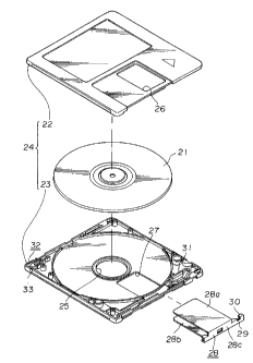
Fig.4 is an exploded perspective view of a disc cartridge
to which the mistaken recording inhibiting mechanism according
to a first embodiment of the present invention is applied.
Fig.5 is a perspective view of the disc cartridge shown in
Fig.4, as seen from the front side fitted with the shutter member
of the disc cartridge shown in Fig.4.
Fig.6 is a perspective view of the disc cartridge shown in
Fig.4, as seen from the rear side.
Fig.7 is an exploded perspective view showing the state in
which the mistaken recording inhibiting member is retained by the
lower half of the cartridge main body.
Fig.B is a partial plan view showing the state in which the
mistaken recording inhibiting member is retained by the lower
half of the cartridge main body with the mistaken recording
detecting hole being closed.
Fi9.9 is a partial plan view showing a lower half and
showing the state in which the 'mistaken recording inhibiting
member is moved to a position of opening the mistaken recording
detecting hole.
Fig.lO is a~partial plan view showing a second embodiment '"
of the mistaken recording inhibiting mechanism for a disc
cartridge according to the present invention.
Fig.l1 is a partial plan view showing a third embodiment of
the mistaken recording inhibiting mechanism for a disc cartridge
8
T~oTyo-..,"~~:~,!~''~
P.;~ _. :~ ;i ~_.y
according to the present invention.
Fig. l2 is a partial plan view showing a fourth embodiment
of the mistaken recording inhibiting mechanism for a disc
cartridge according to the present invention.
Fig.l3 is a perspective view showing a fifth embodiment of
the mistaken recording inhibiting mechanism for a disc cartridge
according to the present invention.
Fig.l4 is a perspective view showing a sixth embodiment of
the mistaken recording inhibiting mechanism for a disc cartridge
according to the present invention.
Fig.lS is an enlarged plan view showing essential parts of
a seventh embodiment of the mistaken recording inhibiting
mechanism for a disc cartridge according to the present
invention.
Fig. l6 is a perspective view of the mistaken recording
inhibiting mechanism according to a seventh embodiment of the
present invention.
Fig.i7 is an enlarged plan view showing the mistaken erasure
inhibiting state in the seventh embodiment shown in Fig. l5.
Fig.l8 is a perspective view showing the state n which a
plurality of disc cartridges each provided with the mistaken
recording inhibiting mechanism are arranged side by side within
a cartridge box.
Fig.lg is a perspective view showing a mistaken recording
inhibiting mechanism according to an eighth embadiment of the
9
~~~~ i~~~~"14 '~~aT7
''_. 'i y
~.l A
present invention.
EMBODIMENT
Referring to the drawings, the mistaken recording inhibiting
mechanism for a disc cartridge according to a first embodiment
of the present invention is hereinafter explained.
The disc cartridge, to which the present invention is
applied, accommodates a magneto-optical disc 21 which permits of
erasure of information signal once recorded thereon and re-
recording of new information signals. The disc cartridge
includes a cartridge main body 24 formed by abutting a
rectangular upper half 22 and a rectangular lower half 23 abutted
and connected to each other. The magneto-optical disc 21 is
rotatably accommodated within the cartridge main body 24.
The cartridge maZn body 24 is formed with a disc entrance
aperture 25 by means of which may be introduced a disc table of
a disc rotating and driving device adapted for rotationally
driving the magneto-optical disc 21 accommodated within the
cartridge main body 24 when the disc cartridge is loaded in
position within the recording/reproducing apparatus.
Specifically, the disc entrance aperture 2~ is a circular opening
formed at a mid part of the lower half 23, as shown in Fig.4, to
permit the inner peripheral region inclusive of a center aperture
21a of the disc 21 accommodated in the cartridge main body 24 to
be exposed to outside. The disc 21 is set on the disc table by
the above-mentioned inner peripheral region.
~,T~IM;"'Jr~,~:~'~
~'.~ S a ,_...r
The upper and lower surfaces of the cartridge main body 24,
that is the upper half 22 and the lower half 23, are formed with
recording/reproducing apertures 26, 27 for exposing at least a
part of the.signal recording region of the disc 21 accommodated
in the cartridge main body to outside across the inner and outer
peripheries of the disc. These recording /reproducing apertures
26, 27 are rectangular in profile and positioned at a mid part
in the transverse direction of the cartridge main body 24 for
extending from a position proximate to the disc entrance aperture
25 to a position lying at the front surface 24a of the cartridge
main body 24, as shown in Fig.4.
Besides, the cartridge main body 24 is provided with a
shutter member 28 adapted for closing the recording/reproducing
apertures 26, 27 for preventing impurities from being intruded
into the cartridge main body 24 via the recording/reproducing
apertures 26, 27 and for being deposited on the magneto-optical
disc 21 accommodated therein. The shutter member 28 is formed
by punching and bending a thin metal sheet into the shape of a
U-shaped cross-section. The shutter member 28 is made up of
shutter plates 28a, 28b for closing the recording/reproducing
apertures 26, 27 and a connecting web 28c connected to the
proximal ends of the shutter plates 28a, 28b and has the shape
of a letter U in cross-section. The connecting web 28c is
extended at one side thereof by a slide guide 29 to permit
parallel movement of the shutter member 28 along a front side 24a
11
v r
of the cartridge main body 24.
The shutte r membe r 28 i s f i tted on the f root s i de of the
cartridge main body 24, with the shutter plates 28a, 28b
overlying the recording/reproducing apertures 26, 27. The
shutter member 28 is mounted in this manner on the cartridge main
body 24 so as to be moved in the directions shown by arrows C and
in Fig.5 between the position of closing the
recording/reproducing apertures 26, 27 and the position of
opening the apertures, as shown by solid lines in Figs.5 and 6.
At a corner of the front side of the lower half 3
constituting the cartridge main body 24, a shutter locking member
31 adapted for being engaged with a mating engaging piece 30
formed by partially bending the slide guide 29 for holding the
shutter member 28 in the closure position is mounted as shown in
Fig.4 for preventing the shutter member 28 from being
inadvertently moved from the position of closing he
recording/reproducing apertures 2.6, 27 shown in Figs.S and 6 for
opening the apertures 26, '27.
At a corner of a rear side 24b of the cartridge main body
24, diametrally opposite to the corner of the front side 24a
fitted with the shutter locking member 37, a mistaken recording
inhibiting member 32 is provided, as shown in Fig.4. This
mistaken recording inhibiting member 32 is provided on the lower
half 23. A detecting hole 33, adapted for being opened and
closed by the mistaken recording inhibiting member 32, is formed
7z
tar, i,._, a d .,t _3 s
at the corner of the rear side 24b vFitted with the mistaken
recording inhibiting member 32. That is, the detecting hole 33
is bored in the lower major surface at the above-mentioned corner
of the rear side 24b of the cartridge main body 24, as shown in
Fig.6.
Referring to Fig.6, the lower major surface of the cartridge
main body 24 provided with the detecting hole 33 has pin-engaging
holes 34, .35 adapted for being engaged by positioning pins, not
shown, adapted for setting the loading position of the disc
cartridge on loading the disc cartridge in a cartridge loading
section within the recording/reproducing apparatus. These pin-
engaging holes 34, 35 are formed at the corners on the front side
24a fitted with the shutter member 28 which is opposite to the
rear side 24b formed wjth the detecting hole 33. The lower major
surface of the cartridge main body 24 is formed with engaging
recesses 36, 37 adapted for being engaged by a cartridge holding
pawl, not shown, of an automatic loading mechanism used for
automatically loading the disc cartridge on the cartridge loading
unit within the recording/reproducing apparatus. These engaging
recesses 36, 3'7 are situated towards a latera~i side 24c which is
at right angles to the lateral side 24a of the cartridge main
body 24 fitted with the shutter member 28 and which is used as
an inserting end into the cartridge loading unit. The engaging
recesses are formed from the lower major surface towards the
front side 24a and towards the rear side 24b.
13
fw ~~_. :i 8 ~.F ~..1 w
The lower major surface of the cartridge main body 24 is
also formed with an indicating recess 38 for indicating that the
disc accommodated within the cartridge main body 24 is the
magneto-optical disc 21, as shown in Fig.6. The indicating
recess 38 is formed at a position on the lateral side 24c as the
inserting end which is proximate to the front side 24a.
The lower major surface of the cartridge main body 24 is
formed with disc type discriminating holes 39, 40 for
discriminating the type of the disc accommodated within the
cartridge main body 24, as shown in Fig.6. These holes 39, 40
are situated towards a latera,l.sade 24d opposite to the lateral
side 24c as the inserting end into the cartridge loading unit in
alignment with the detecting hole 33.
The mistaken recording inhibiting member 32, provided within
the cartridge main body 24, is molded from synthetic resin, and
has a substantially square-shaped closure web 41 at the proximal
side which is at least of a size to close the detecting hole 33,
as shown in Fig.7. Extended from the one end face of the closure
web 41 are a pair of resiliently defelctible resilient arms 42,
43 arranged side by side and a movement actuating arm 44, as an
movement actuating member, arranged substantially parallel to
these resilient arms 42, 43.
The resilient arms 42, 43 are of different lengths such that
the resilient arm 43 is longer in length than the resilient arm
42. Retention beads 45, 46 are formed at the distal ends of the
14
'~'~ ~~ "~ X71 .~.. T, a
J J ..e) ,.J ~
resilient arms 42, 43 for extending towards each other. By
forming the retention beads 45, 46 at the distal ends of the
resilient arms 42, 43 of the different lengths, these retention
beads 45, 46 may be engaged with each other, as shown in Fig.7.
A movement actuating bead 47 is also formed at the distal
end of the movement actuating arm 44 for being extended
outwardly, that is in a direction opposite to the beads of the
resilient.arms 42, 43.
On the inner surface of the lower half 23 of the cartridge
main body 24 provided with the mistaken recording inhibiting
member 32, an upstanding slide guide 48 adapted for guiding the
resilient arms 42, 43 of the mistaken recording inhibiting member
32 during movement thereof and also adapted for being clamped by
the resilient arms 42,, 43 is formed, as shown in Fig.7. The
slide guide 48 is formed parallel to an upstanding peripheral
wall 49 on the lower half 23 which is used as a wall surface of
the rear side 24b of the cartridge main body 24.
The slide guide 48 is formed with first and second engaging
recesses 50, 51 engaged by the retention bead 45 at the distal
end of the resilient arm 42. These first and second engaging
recesses 50, 51 are formed by arcurately bending part of the
slide guide 48 at the positions at which the engaging recesses
are engaged by retention rib 45 when the mistaken recording
inhibiting member 32 is moved to the position of closing and
opening the detecting hole 33.
W;e.f;:...",_~~~:~ '?~
~.r'...' ~ r .~
The rear side 24b of the cartridge main body 24 is formed
with a notch 52 to permit the movement actuating boss 47 of the
movement actuating arm 44 to be protruded outwardly in a
directian away from the resilient arms 42, 43, as shown in Fig.6.
The notch 52 is formed by partially cutting the upstanding
peripheral wall sections 49 of the upper and lower halves 22, 23
making up the wall of the rear side 24b of the cartridge main
body 24. .'The notch 52 is of a width to permit the mistaken
recording inhibiting member 32 to be moved between the position
of closing the detecting hole 33 and the position of opening the
detecting hole 33.
A barrier wall 54 is formed within the lower half 52 for
facing the notch 52. The barrier wall 54 controls the resilient
deflection of the movement actuating arm 44 towards the inside
of the cartridge main body 24, while controlling viewing of the
inside of the cartridge main body 24 by covering the notch 52.
The mistaken recording inhibiting member 2 is situated on
the inner surface of the lower half 23, as shown in Fig. B, with
the closure web 41 lying towards the detecting hole 33 and with
the resilient arms 42, 43 clamping the slide guide 48, the
movement actuating arm 44 being extended between the upstanding
peripheral wall 49 and the barrier wall 54.
Since the mistaken recording _inhibiting member 32, thus
provided within the lower half 23, holds the slide guide 48 by
the resilient arms 42, 43, it is held positively by the lower
16
P.d'~", i ;1 n.G ...Y ~~
half 23 without being readily detached therefrom. With the
mistaken recording inhibiting member 32 thus arranged on the
lower half 23, the mistaken recording inhibiting member 32 is
exposed to the outside of the cartridge main body 24 via notch
52.
With the mistaken recording inhibiting member 32 thus held
by the lower half 23 and arranged within the cartridge main body
24, the movement actuating boss 47 exposed towards the outside
of the rear side 24b of the cartridge main body 24 via notch 52
may be acted upon for sliding the mistaken recording inhibiting
member 32 in the direction shown by arrow E and arrow F in Fig. S,
with the resilient arms 42, 43 being then guided by the slide
guide piece 48.
When the closure,web 41 is in the position of closing the
detecting hole 33, the retention bead 45 formed at the distal end
of the resilient arm 42 is engaged in the engaging recess 50
formed in the slide guide 48, as shown in Fig. B, for maintaining
the detecting hole 33 in the closed state.
With the detecting hole 33 thus closed by the closure web
32, mistaken recording detection means provided in the
recording/reproducing apparatus is prevented from being intruded
into the detecting hole 33 to permit information signal to be
recorded on the magneto-optical disc 21 accommodated within the
cartridge main body 24.
When the mistaken recording inhibiting member 32 is slid in
17
s'e~ry~.~.Ay. '~. "O
dd~.~ r :~ ~ .~ w
the direction shown by arrow E in Fig.B until the closure web 41
reaches the position of opening the detecting hole 33, the
retention bead 45 formed at the distal end of the resilient arm
42 is engaged in the second engaging recess 51 formed in the
slide guide 48 to maintain the detecting hole 33 in the opened
state.
With the detecting hole 33 thus opened by the mistaken
recording.inhibiting member 32, the detecting hole 33 is detected
by mistaken recording detecting means provided in the
recording/reproducing, apparatus to inhibit recording of
information signals on the magneto-optical disc 21 accommodated
in the cartridge main body 24.
When the mistaken recording inhibiting member 32 is moved
in the direction of opening the detecting hole 33, the retention
bead 46 formed at the distal end of the resilient arm 43 rides
over the second engaging recess 51 so as to be moved. When the
mistaken recording~inhibiting member 32 reaches the position of
opening the detecting hole 33, it is abutted against the slide
wide 48. Thus the mistaken recording inhibiting member 32 is
controlled in its movement in the direction shown by arrow F in
Fig.9 of closing the detecting hole 33 for reliably maintaining
the detecting hole 33 in the opened position.
Meanwhile, the lower half 23 is provided with a guide lug
55 for positively guiding the mistaken recording inhibiting
member 32 in the direction of closing the detecting hole 33 when
78
"a_ ;~.".,."~~'a-~7~
l~r ~~..., x:I . .~ ~.) s
the mistaken recording inhibiting member 32 is moved in the
direction of closing the detecting hole 33 as shown by arrow F
in Fig.9. An inclined guide surface 56 adapted to be guided by
the guide lug 55 is formed on the mistaken recording inhibiting
member 32 by chamfering the corner of the closure web 41.
Although the resilient arm 42 having the retention bead 45
adapted for being engaged by the first and second engaging
recesses 50, 51 formed in the slide guide 48 is provided on the
outer side in the above-described first embodiment, the relative
disposition of the resilient arms 42, 43 may be reversed, by way
of a second.embodiment, as shown in Fig.lO,. In such case, the
first and second guide recesses 50, 51 are formed in the slide
guide 48 for being extended at the opposite surface with respect
o the first embodiment.
In the above-described embodiments, the slide guide 48 is
partially extended arcurately for defining the first and second
engaging recesses 50, 51, while the resilient arms 42, 43 are of
different lengths so that only the retention bead 45 formed at
the distal end of the resilient arm 42 is engaged in the first
and second engaging recesses 50, 51. In a~ third embodiment,
shown in Fig.ll, the slide guide 48 is formed on its both sides
with grooves 50a, 50b, 51a, 51b for defining the first and second
engaging recesses 50, 51. In this case, the resilient arms 42,
43 are of the same length. ~y forming the resilient arms 42, 43
and the first and second engaging recesses 50, 51 in the above-
19
a ;~ ~s;ss~_"~, ~:"/ 4:: rd
OxJ ~_. '~ d ~ ~_D ~~
described manner, the retention beds 45, 46 at the distal ends
of the resilient arms 42, 43 are engaged in the first and second
engaging recesses 50, 51, so that both the resilient arms 42, 43
play the role of clamping the slide guide 48 and positioning the
mistaken recording inhibiting member 32.
The engaging system for relative engagement between the
resilient arms 42, 43 holding the mistaken recording inhibiting
member 32.in the position of closing the detecting hole 33 and
the position of opening the detecting hole 33 may also be
reversed from the disposition shown in the above embodiments.
That.,is, as shown in Fig. l2 as a fourth embodiment, part of
the slide guide 48 may be arcuately extended to form first and
second extended portions 61, 62, while the distal end parts of
the resilient arms 42, 43 may be formed with engaging recesses
63, 64 adapted for being mated with the first and second extended
portions 61, 62 so that the mistaken recording inhibiting member
32 may be maintained in the position of closing or opening the
detecting hole 33 by engagement of the first and second extended
portions 61, 62 with the engaging recesses 63, 64.
Although the foregoing description has been made with
reference to an example of a disc cartridge comprised of the
cartridge main body 24 accommodating the magneto-optical disc
21 therein, the present invention may also be applied in general
to a disc cartridge accommodating a disc capable of recording
information signals.
1' ' ~- ,t.J
.4 ~,.. .~ .f F v.) aC
In the above-described embodiments of the mistaken recording
inhibiting system, the movement actuating part of the mistaken
recording inhibiting member is acted upon via the notch farmed
in the lateral surface of the cartridge main body. However, in
the above embodiments, since the notchlis of a small size, it is
extremely difficult to catch the actuating part of the mistaken
recording inhibiting member with the finger or nail to cause the
movement of the mistaken recording inhibiting member.
A modification of the present invention which has overcome
this inconvenience is hereinafter explained.
Fig. l3 shows a mistaken recording~ inhibiting system
according to a fifth embodiment of the present invention. The
parts or components which are used in common with those of the
preceding embodiments, are indicated by the same numerals and
reference is had to the description of the preceding first
embodiment. In Fig.l3, 522 is a notch which is formed in the
rear side 24b of the cartridge main body 24 and through which
a mistaken recording inhibiting member 44 may be acted upon by
the finger or nail. The notch 522 is formed for extending from
the major surface of the lower half 23 to the rear side 24b of
the cartridge main body 24. Since the notch 522 may be
increased in size as compared to the notch of the preceding
embodiment, the mistaken recording inhibiting member 44 rnay be
actuated more easily without regard to the size of the finger or
nail.
21
T:,>~ .""~ rCr'S:: ' ?
a a ..._a ~
Fig. l4 shows a sixth embodiment of the mistaken recording
inhibiting member of the disc cartridge according to the present
invention. In the present sixth embodiment, parts or components
which are used in common with the preceding embodiments are
indicated by the same numerals and reference is had to the
description of the preceding fourth embodiment.
In Fig. l4, 523 is a notch which is formed in the rear side
24b of the cartridge main body 24 and through which a mistaken
recording inhibiting member 44 may be acted upon by the finger
or nail. The notch 523 is formed for extending from the major
surface of the upper half 22 to the rear side 24b of the
cartridge main body 24. Since the notch 523 may be increased
in size as compared tolthe notch of the preceding embodiment, the
mistaken recording inhibiting member 44 may be actuated -more
easily as in the preceding fifth embodiment.
In the mistaken recording inhibiting system for the disc
cartridge according to a seventh embodiment of the present
invention, a notch 117 for acting on a-mistaken recording
inhibiting member 118 is formed on end surfaces from the end of
rear side 24b towards the end of the lateral side 24d of the
cartridge main body 24. The notch 117 has a rear side notch
section 117b on the rear side 24b and a lateral side notch
section 117a on the lateral side 24d. The rear side notch
section 117a on the lateral side 24d is of a length which will
permit the mistaken recording inhibiting member 118 to be moved
22
,~:a~f':~r"';~.~.~4,, t'""~
h~vl ~,., d :i ~:_l M
between the lateral side position with respect to the detecting
hole 33~and the open position of the detecting hole 33, while the
rear side notch section 117b on the lateral side 24d is of a
length corresponding to the width of the base section 118a which
is the main body section of the mistaken recording inhibiting
member 118. The above-mentioned supporting piece 110 and the
engaging piece 111 are arranged forwardly from the lateral notch
section 117a of the notch 117.
The mistaken recording inhibiting member 118, arranged
within the notch 117, has its first engaging extension 118b
slidably introduced into a space between the rear side 24b of the
cartridge main body 24 and the supporting piece 110 for s Tiding
in the fore-and-aft direction, while having its second and third
engaging extensions 11~d, 118e associated with the engaging piece
111. The outer lateral surface of the end of the base part 118a
of the mistaken recording inhibiting member 118 has its end
exposed at the lateral notch section 117a of the notch 117 so as
to be flush with the rear side 24b , while the rear end face
thereof is exposed at the rear notch section 117b so as to be
flush with the lateral side 24d. With the bass section 118a
covering the detecting hole 33, the outer lateral surface and the
rear end face thereof make up a part of the corner of the
cartridge main body 24. The outer lateral surface of the base
section 118a of the mistaken recording inhibiting member 118 is
provided with a recessed finger rest on which the finger may be
23
Q'~ .!f'.: ~~..,_g t'?W, ..R
Fw '~..,~ .,~ a L,; ,J ~
applied in parallel state with respect to the upper and lower
surfaces of the cartridge main body 24.
The above-described mistaken recording inhibiting system of
the seventh embodiment operates as follows.
When recording information signals, the mistaken recording
~1
inhibiting member 118 is so arranged that the base section 118a
thereof is positioned at a corner of the cartridge main body 24,
that is, the rear end face thereof is flush with the lateral side
24d, with the detecting hole 33 being closed (Fig.l5). In this
position of the mistaken recording inhibiting member 118, the
bead 118d' of the second engaging extension 118d is abutted on
the outer lateral surface 111c of the engaging piece 111 of the
cartridge main body 24, while the bead 118e' of the third
engaging extension 11.8e is engaged in the recess 111a of the
engaging piece 111" so that the mistaken recording inhibiting
member 118 is retained and held with respect to the cartridge
main body 24 by the clamping of .the engaging piece 111 by the
engaging extensions 118d, 118e.
When erasing the incorrect recording after recording, the
base section 118a of the mistaken recording irihibiting member 118
is thrust in a forward direction from the lateral side 24d of the
cartridge main body 24 with the finger applied in a parallel
state relative to the upper and lower surfaces of the cartridge
main body 24.
In this manner, the mistaken recording inhibiting member 118
24
n ..,r~,:, ".y.»uv-i~
Pa ~... 7 a a _j a
is moved so that he first engaging extension 118b is introduced
deep into a space between the supporting piece 110 and the rear
side 24b of the cartridge main body 24, while the second engaging
extension 118d is slid along the outer lateral surface lilc of
the engaging piece 111. On the other hand, the third engaging
extension 118e is disengaged from the rear recess 111a of the
engaging piece 111 and retained by being engaged with the forward
recess 111b.
The result is that the base section 118a of the mistaken
recording inhibiting member 118 is introduced from the lateral
side 24d of the cartridge main body 24 into the interior thereof
while the base section is maintained in a flush state relative
to the rear side 24b.of the cartridge main body 24. In this
manner, the detecting,hole 33 is opened to permit intrusion of
the mistaken recording inhibition detecting pin of the
recording/reproducing apparatus (Fig.l7).
For resetting~the cartridge.main body 24 from the mistaken
recording inhibiting position to the recordable position, the
mistaken recording inhibiting member 118 is thrust towards the
lateral side 24d by applying a finger at the finger rest 118f
formed on the outer lateral surface of the base section 118a in
a di rection parcel lel to the upper and lower surfaces of the
cartridge main body 24.
Since the notch 117 is formed in the present seventh
embodiment for being extended from the rear side 24b to the
,r~ T~,tF.~....~'yt ~,,", _..d
W ' . , a W . _.:i w
lateral side 24d of the cartridge main body 24, the finger's end
may be.introduced easily and a positive operation may be assured
even if the nail is in a trimmed state. Inhibition of mistaken
recording and resetting from the state of inhibition of mistaken
recording to the recordable state may be achieved by simply
moving the finger's end in a direction at right angles to the
bending direction of the finger without the necessity of
employing.a pointed operating tool.
Above all, the mistaken recording inhibiting operation by
the mistaken recording inhibiting member may be achieved easily
so that the disc cartridge may be set to the mistaken recording
inhibiting state easily and positively.
In addition, in. the present seventh embodiment, since
feasibility of recording/reproduction may be checked depending
on whether or not the mistaken recording inhibiting member 118
is receded into the inside of the cartridge main body 24, it is
possible to check for feasibility of recording/reproduction of
a plurality of disc cartridges placed side by side in a box B as
shown in Fig.lB.
In the seventh embodiment, the finger rest 118f is formed
on the surface of the base section 118a of the mistaken recording
inhibiting member 118. Alternatively, the lateral end side of
the notch section 117a of the notch 117 of the cartridge main
body 24 may be formed with a gap by which the finger's end may
be inserted between it and the base section 118a of the mistaken
28
P~W -_, i i .. ..'l t
recording inhibiting member 118 moved to the open position.
Referring to Fig. l9, an eighth embodiment of the present
invention is explained. Parts or components similar to those of
the seventh embodiment are indicated by the same numeral and
detailed description thereof is omitted.
With the mistaken recording inhibiting system of the disc
cartridge of the present eighth embodiment, a notch 127 is formed
only in the lateral side 24d of the cartridge main body 24 fo-r
extending a longer distance forwardly from the vicinity of the
ejecting hole 33, that is, the notch 127 has a length longer than
that of the notch of the preceding embodiment.
The mistaken recording inhibiting member 128 associated with
the notch 127 is positioned in its entirety in the cartridge main
body 24. The first engaging extension 128b is adapted to be
flush with the lateral surface of the base section 128a and is
of a length longer than the second engaging extension, that is
of a length long enough to close the notch 127, and a finger rest
128c is formed at a mid part of the outer lateral surface of the
first engaging extension 128b. That is, the finger rest 128c is
formed on the first engaging extension 128b~at such a position
that,. when the mistaken recording inhibiting member 128 is moved
to a position of closing the detecting hole 33, the nail's end
may be inserted between. the finger rest and the rear edge 127b
of the notch 127 in parallel with the upper and lower surfaces
of the cartridge main body 24 and, when the mistaken recording
27
'-":f'~''"""' ~~a "a
~~ ~.. 4 ./...A ~~_/ 4
inhibiting member 128 is moved to a position of opening the
detecting hole 33, the nail's end may be inserted between the
finger rest and the forward edge 127a of the notch 127 in
parallel with the upper and lower surfaces of the cartridge main
body 24.
Since the notch 727 is formed with a longer length in the
fore-and-aft direction of the lateral wall of the cartridge main
body 24, the nail's end may be inserted in a position parallel
to the upper and lower surfaces of the cartridge main body 24,
similarly to the first embodiment, to catch the mistaken
recording inhibiting member 28, while mistaken erasure may be
inhibited by simply moving the nail's end in a direction at
right angles to the bending direction of the finger.
With the above-,described mistaken recording inhibiting
system for the disc cartridge according to the present invention,
since the mistaken recording inhibiting member is moved by
guiding the resilient arms separated from the movement actuating
member by the slide guide'provided in the cartridge main body,
so that stable movement may be achieved.
Besides, since the mistaken recording inhibiting member is
arranged within the cartridge main body with the slide guide
being clamped by the resilient arms, the mistaken recording
inhibiting member may be positively maintained within the
cartridge main body without the risk of detachment during and
after assembling of the disc cartridge.
28
F.u~.. r~ 'n..sr.f..~';.ar
In addition, the mistaken recording inhibiting member may
be maintained in the positions of opening or closing the mistaken
recording detecting hole by engagement with engaging means
provided between at least one of the resilient arms and the slide
guide, so that the recordable state permitting recording of
information signals and the mistaken recording inhibiting state
may be established reliably.
Above all, since the mistaken recording inhibiting member
is arranged within the cartridge main body and designed for
clamping the slide guide by the resilient arms separated from the
movement actuating part, the mistaken recording inhibiting member
may be maintained within the cartridge main body, with the slide
guide being positively clamped by the resilient arms, even when
it is molded from synthetic resin.
Since the mistaken recording detecting hole is formed in the
major surface of the cartridge main body and the movement
actuating section for actuating the mistaken recording inhibiting
member into movement is exposed to the rear surface which is at
right angles to the major surface of the cartridge main body, the
mistaken recording inhibiting member may be reduced in size and
the housing space within the cartridge main body may be
diminished so that the present system may be applied
advantageously to small-sized disc cartridge.
29