Language selection

Search

Patent 2077992 Summary

Third-party information liability

Some of the information on this Web page has been provided by external sources. The Government of Canada is not responsible for the accuracy, reliability or currency of the information supplied by external sources. Users wishing to rely upon this information should consult directly with the source of the information. Content provided by external sources is not subject to official languages, privacy and accessibility requirements.

Claims and Abstract availability

Any discrepancies in the text and image of the Claims and Abstract are due to differing posting times. Text of the Claims and Abstract are posted:

  • At the time the application is open to public inspection;
  • At the time of issue of the patent (grant).
(12) Patent: (11) CA 2077992
(54) English Title: MAINTENANCE TERMINATION UNIT FOR ISDN
(54) French Title: UNITE TERMINALE POUR RNIS
Status: Deemed expired
Bibliographic Data
(51) International Patent Classification (IPC):
  • H04M 3/22 (2006.01)
  • H04L 12/26 (2006.01)
  • H04L 12/52 (2006.01)
  • H04M 3/24 (2006.01)
  • H04M 3/30 (2006.01)
  • H04Q 11/04 (2006.01)
(72) Inventors :
  • DEBALKO, GEORGE ANDREW (United States of America)
(73) Owners :
  • AMERICAN TELEPHONE AND TELEGRAPH COMPANY (United States of America)
(71) Applicants :
(74) Agent: KIRBY EADES GALE BAKER
(74) Associate agent:
(45) Issued: 1998-04-21
(22) Filed Date: 1992-09-10
(41) Open to Public Inspection: 1993-04-05
Examination requested: 1992-09-10
Availability of licence: N/A
(25) Language of filing: English

Patent Cooperation Treaty (PCT): No

(30) Application Priority Data:
Application No. Country/Territory Date
771,664 United States of America 1991-10-04

Abstracts

English Abstract


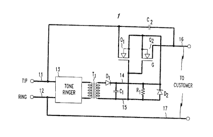
Disclosed is a Maintenance Termination Unit (MTU) for an Integrated
Services Digital Network (ISDN). A tone ringer is provided at the end of the
customer loop to generate an AC signal. The signal is applied through a transformer
and rectifier to charge a capacitor. The resulting voltage across the capacitor causes
a normally closed MOS switch to open and disconnect the customer until the
capacitor discharges.


French Abstract

On présente ici une Unité de terminaison de maintenance (MTU) pour un réseau à intégration de services numériques (RNIS). Une sonnerie électronique est installée à l'extrémité de la boucle du client pour générer un signal CA. Ce signal est appliqué au travers d'un transformateur et d'un redresseur à un condensateur pour le charger. La tension résultante aux bornes du condensateur provoque l'ouverture d'un interrupteur MOS normalement ouvert et déconnecte le client pendant toute la durée de décharge du condensateur.

Claims

Note: Claims are shown in the official language in which they were submitted.


-4-

Claims:
1. A maintenance termination unit comprising:
means responsive to a ringing signal for generating an AC signal;
means for rectifying the AC signal;
a capacitor coupled to the rectifying means; and
a normally closed semiconductor switch coupled to the capacitor such
that when the capacitor is charged the switch will open.

2. The unit according to claim 1 wherein the switch comprises a pair of
normally conducting MOS field effect transistors.

3. The unit according to claim 2 wherein the MOSFETs have a common
gate electrode coupled to one plate of the capacitor, and a common source regioncoupled to the other plate of the capacitor.

4. The unit according to claim 3 wherein the drain of one MOSFET is
coupled to a ring conductor adapted for coupling to a central office and the other
MOSFET has a drain coupled to a ring conductor adapted for coupling to a
customer's equipment.

5. The unit according to claim 1 wherein the means for generating an AC
signal comprises a tone ringer circuit.

6. The unit according to claim 1 wherein the rectifying means comprises
a semiconductor diode.

7. The unit according to claim 1 further comprising a transformer
coupled between the means for generating the AC signal and the means for
rectifying the AC signal.

8. The unit according to claim 1 further comprising a resistor coupled in
parallel with the capacitor.

9. The unit according to claim 8 wherein the resistor has a resistance in
the range 10-30 megohms.

-5-

10. The unit according to claim 1 wherein the capacitor has a capacitance
in the range 2-10 microfarads.

11. The unit according to claim 1 wherein the unit includes a tip
conductor and ring conductor, the switch is coupled to disconnect a customer from
the tip conductor, and further comprising an additional switch coupled to disconnect
the customer from the ring conductor.

12. A maintenance termination unit comprising:
input tip and ring conductors adapted to be coupled to a central office,
and output tip and ring conductors adapted to be coupled to a customer's equipment;
a tone ringer circuit having its input coupled to the input tip and ring
conductors;
a transformer with a first winding coupled to the output of the tone
ringer circuit;
a rectifying diode coupled to a second winding of the transformer;
a capacitor coupled to the rectifying diode;
a resistor coupled in parallel with the capacitor; and
a pair of normally conducting MOSFETs having a common gate
electrode coupled to one plate of the capacitor and a common source region coupled
to the other plate of the capacitor, a drain region of one transistor coupled to the
input tip conductor and a drain region of the other transistor coupled to the output tip
conductor.

13. A unit according to claim 12 further comprising a ground conductor
and a bridge circuit coupled to the tone ringer circuit.

Description

Note: Descriptions are shown in the official language in which they were submitted.


- 1 -
MAINTENANCE TERMINATION UNIT FOR ISDN
Back~round of the Invention
This invention relates to Maintenance Terrnination Units (MTUs).
Maintenance termination units are utilized to disconnect the customer
5 from the telecommllnic~ions network in order to deterrnine if any problems which
exist are in the customer equipment or in the network equipment. Present Plain Old
Telephone Service (POTS) MTUs generally rely on the presence of a DC current on
the line to close a solid state switch when the customer is off-hook.
Integrated Services Digital Network (ISDN) is a digital transrnission
10 system whish will prosdde voice, data and video information over custQmer lines.
One of the problems with such a network is hQw to provide an MTU in the customerloop. Since there is sometimes no current to the customer, use of standard MTUs
would result in a disconnection while the customer is off-hook.
Summary of the InYention
The invention is a maintenance termination unit comprising means
responsive to a ringing signal for generating an AC signal, means for rectifying the
signal, and a capacitor coupled to the rectifier means. The unit further comprises a
normally closed semiconductor switch. The capacitor is coupled to the switch such
that when the capacitor is charged, the switch will open.
20 Brief Description of the Drawing
These and other features of the invention are clelin~ d in detail in the
following description. In the drawing:
FIG. 1 is a schematic circuit diagram of an MTU in accordance with an
embodiment of the invention;
FIG. 2 is a schematic circuit diagram of an MTU in accordance with a
further embodiment of the invention; and
FIG. 3 is a schematic circuit diagram of a portion of an MTIJ in
accordance with a further embodiment.
Detailed Description
A maintenallce termination unit in accordance with one embodiment is
illustrated in FIG. 1. Data, voice, or video signals are supplied from the central
office to input tip and ring conductors 11 and 12. The incorning signals are supplied
to a tone ringer circuit 13. The tone ringer circuit is a co~ ..;ially available circuit
designed to produce an AC signal (tone~ in response to a ringing signal on the
35 lines 11 and 12. One such circuit, which is generally used to create AC tones on
speakerphones, is made by Motorola under the designation MC 34017-2P.


f~


Typically, the AC signal will have a frequency in the range 100-1000 ~Iz and a peak
amplitude in the range 1-5 volts.
The output of the tone ringer is coupled to a transformer, T I, which is
used to isolate the remainder of the unit frorn voltages on the tip and ring conductors.
5 Typically, the transforrner, T I, has a turn ratio of 1:1. The output of the transforrner
is coupled to a rectifying means which, in this example, is a standard silicon
rectifying diode D I .
A capacitor, C I, has one plate coupled to conductor 14 extending from
the cathode of the diode D I and its other plate coupled to conductor 15 extending
10 from the secondary winding of the transforrner T1 . Generally, the capacitance of C
should be within the range 2-10 microfarads. Coupled in parallel with the capacitor
C I is a resistor R I which, for reasons to be discussed, has a resistance in the range
10-30 megohms. A zener diode D2 is also coupled in parallel with c~p~ri~-r C I and
resistor R I .
A pair of MOS Field Effect Transistors (MOSFETs), Q I and Q2, have a
cornmon gate electrode G coupled to conductor 15 and a cs~mmon source region
coupled to conductor 14. The drain region of transistor Q 1 is coupled to the tip
conductor 11, and the drain of transistor Q2 iS coupled to the output tip conductor 16
which is connected to the customer equipment. l'he transistors Q 1 and Q2 are
20 norrnally conducting, depletion mode MOSFETs. A capacitor C2 iS coupled across
the two transistors Q 1 and Q2 tO minimi7e losses of high frequency signals through
the circuit during norrnal transmission by providing a path which ~ypasses Q I an,1
Q2 for such signals. C2 generally has a value in the range 0.1 to 1 microfarads.During the norrnal operation of the customer e~uipment, transistors Q
25 and Q2 will be conducting so that the circuit of FIG. 1 is transparent to the central
of fice and customer. If, however, a service problem should develop, or if the central
office merely wants to conduct a routine test, a ringing signal is transmitted from the
central office and appears on conductors 11 and 12. This signal, which norrnally has
a frequency of approximately 20 Hz and an RMS amplitude of a~ u~hllately
30 84 RMS, is not used in the norrnal operation of ISDN systems. The tone ringcr, 13,
detects the presence of the ringing signal and, in response, produces an AC signal at
its output. This signal is applied to transforrner T I and to diode D I for rectification.
The rectified signal is used to quickly charge up capacitor C I . ~hen
the voltage across the capacitor reaches a certain level, in this exa~nple
35 approximately 2 volts, the depletion mode MOSFETs ~21 and Q2 will be renderednon-conductive as a result of the corresponding voltage established between the


gate G and source regions of the MOSFETs. The customer is thereby cut off from
the network while standard tests can be perforrned to determine if any problem exists
in the network.
The MOSF;ETs will remain non-conducting for a period of time
S depending on the value of R I since the capacitor C I will be discharging through R
during this disconnect interval. It is generally desirable to keep the customer
disconnected for a period of 30-180 seconds. Consequently, a resistance of R I in
the range 6-30 megohms is appropriate. Once the capacitor C I has discharged
below a certain level, MOSFETs Q I and Q 2 will resume their norrnal conducting
10 state, and further tests can then be performed on the customer equipment.
The diode D 2 serves as a protector element. In the event that too much
voltage is generated across conductors 14 and 15, D2 will break over and conductcurrent away from the capacitor.
FIG. 2 illustrates an alternative embodiment where elernents
15 corresponding to those of FIG. 1 are similarly numbered. In this embodiment, a
second pair of MOSFETs, Q3 and Q4, are coupled to the output ring conductor 17 to
provide an additional switch. The additional switch is operated by a similar
combination of transforrner T2 coupled to the tone ringer, 13, a rectifying diode D3,
capacitors C3 and C4, a resistor R2 and a zener diode D4. This circuit perrnits both
20 central office tip and ring conductors 11 and 12 to be disconnected from the
customer. The circuit will also add additional impedance to the lines, which can be
minimi7f~d by the presence of capacitors C2 and C4 to bypass transistors Q I - Q4
for high frequency signals.
Various additional modifications will become apparent to those skilled
25 in the art. In the FIG. 2 embodiment, a single 3-winding transformer can replace Ihe
t~o transforrners Tl and T2. Further, a MOSFET with one input and two outputs,
each coupled to one of the output tip and ring conductors, could simplify the
circuitry of FIG. 2 by eliminatil~g T 2, ~ 3, C 2, R 2 and D 4 -
Also, as shown in FIG. 3 a bridge circuit including tip, ring, and ground
30 conductors can be used to provide the incoming signal to the tone ringer 13. Thismodification would ensure that ~he MTU would operate even if there is a short
between tip and ring by applying the signal between tip or ring and ground.
All such variations which basically rely on the teachings through which
the invention has advanced the art are properly considered within the scope of the
35 invention.

Representative Drawing
A single figure which represents the drawing illustrating the invention.
Administrative Status

For a clearer understanding of the status of the application/patent presented on this page, the site Disclaimer , as well as the definitions for Patent , Administrative Status , Maintenance Fee  and Payment History  should be consulted.

Administrative Status

Title Date
Forecasted Issue Date 1998-04-21
(22) Filed 1992-09-10
Examination Requested 1992-09-10
(41) Open to Public Inspection 1993-04-05
(45) Issued 1998-04-21
Deemed Expired 2010-09-10

Abandonment History

There is no abandonment history.

Payment History

Fee Type Anniversary Year Due Date Amount Paid Paid Date
Application Fee $0.00 1992-09-10
Registration of a document - section 124 $0.00 1993-04-02
Maintenance Fee - Application - New Act 2 1994-09-12 $100.00 1994-07-19
Maintenance Fee - Application - New Act 3 1995-09-11 $100.00 1995-07-27
Maintenance Fee - Application - New Act 4 1996-09-10 $100.00 1996-07-16
Maintenance Fee - Application - New Act 5 1997-09-10 $150.00 1997-07-21
Final Fee $300.00 1997-12-22
Maintenance Fee - Patent - New Act 6 1998-09-10 $150.00 1998-06-22
Maintenance Fee - Patent - New Act 7 1999-09-10 $150.00 1999-06-19
Maintenance Fee - Patent - New Act 8 2000-09-11 $150.00 2000-06-19
Maintenance Fee - Patent - New Act 9 2001-09-10 $350.00 2002-09-06
Maintenance Fee - Patent - New Act 10 2002-09-10 $200.00 2002-09-06
Maintenance Fee - Patent - New Act 11 2003-09-10 $200.00 2003-08-21
Maintenance Fee - Patent - New Act 12 2004-09-10 $250.00 2004-08-19
Maintenance Fee - Patent - New Act 13 2005-09-12 $250.00 2005-08-05
Maintenance Fee - Patent - New Act 14 2006-09-11 $250.00 2006-08-08
Maintenance Fee - Patent - New Act 15 2007-09-10 $450.00 2007-08-08
Maintenance Fee - Patent - New Act 16 2008-09-10 $450.00 2008-08-11
Owners on Record

Note: Records showing the ownership history in alphabetical order.

Current Owners on Record
AMERICAN TELEPHONE AND TELEGRAPH COMPANY
Past Owners on Record
DEBALKO, GEORGE ANDREW
Past Owners that do not appear in the "Owners on Record" listing will appear in other documentation within the application.
Documents

To view selected files, please enter reCAPTCHA code :


To view images, click a link in the Document Description column. To download the documents, select one or more checkboxes in the first column and then click the "Download Selected in PDF format (Zip Archive)" or the "Download Selected as Single PDF" button.

List of published and non-published patent-specific documents on the CPD .

If you have any difficulty accessing content, you can call the Client Service Centre at 1-866-997-1936 or send them an e-mail at CIPO Client Service Centre.


Document
Description 
Date
(yyyy-mm-dd) 
Number of pages   Size of Image (KB) 
Cover Page 1998-04-03 1 39
Cover Page 1993-12-18 1 15
Description 1993-12-18 3 159
Abstract 1993-12-18 1 11
Claims 1993-12-18 2 61
Drawings 1993-12-18 2 37
Representative Drawing 1998-04-03 1 8
Correspondence 1997-12-22 1 42
Fees 2002-09-06 1 34
Prosecution Correspondence 1993-07-13 1 33
Examiner Requisition 1996-09-20 2 81
Prosecution Correspondence 1996-12-19 1 49
Office Letter 1997-02-10 1 46
Prosecution Correspondence 1997-03-20 2 87
Office Letter 1993-04-23 1 66
Fees 1996-07-16 1 85
Fees 1995-07-27 1 57
Fees 1994-07-19 1 60