Note: Descriptions are shown in the official language in which they were submitted.
2078197
PAGING ARRANGEMENTS IN A CELLULAR MOBILE SWITCHING SYSTEM
Technical Field
This invention relates to paging arrang~llællls for cellular mobile
telecol.""~ ications systems.
S ~bl-m
Mobile radio ~y~ s for pc~ ;II;ng customers caUing from mobile
stations such as vehic~ r stations mounted in automobiles, portable stations of
meAillm weight which may be transported readily, or small lightweight, hand held~cl~nal co.. -~nication stations are becoming increasingly prevalent. Such systems
10 use the principles of cellular technc-logy to allow the same frequencies of a col~llo
allocated radio bandwidth to be reused in separated local areas or cells of a broader
region. Each cell is served by a base transceiver station comprising a group of local
tlal~scei~/ers connecte~l to a coll~oll ~ntenn~ The base station ~y~ s, each
compri~ing a controller and one or more transceiver stations are in~l.;ol-nccted via a
15 ~wi~l ing system, a mobile ~witching center, which is also connected to the public
switched tclephone r,ctwc.lL. Such cellular ~y~t~ S are now ent~ring a second
gel~.~lion characterized by digital radio co.. ~.-ications and a dirrelen~ set of
standards such as the Eulupeall Global Systems for Mobile Co.. l.ic~tion~ (GSM)
standard, promlllg~tçd by the Special Mobile Group (SMG).
In such moWe teleco.".. ~ll-ic~tions ~ysle~s~ if an incoming call is
received in a mobile teleco.. ,~.-icati- ns ~wilcl ing system, and the call destin~tion
is a mobile stadon, that mobile station must be paged. According to the principles of
the GSM standards, a mobile stadon that is idle, but has its power on, is tuned to a
control channel which incl~des a paging subch~nnçl of the base transceiver station
25 from which it receives the strongest signal. Thus, as the mobile moves from cell to
cell, it is con~ltly retuning its control channel receiver. Further, base transceiver
stations are ~Ju~d into location areas. Whelle~er an idle mobile moves from a cell
in one loc~tion area to a cell in another location area, it l,al slllils a control message
to the base tr~n~ceiver station of the new location area and thence to the Visitor
30 ~ oc~tion Register (VLR) to request that its location area identifiçr be llpd~ted The
object of this procedure is to limit the number of transceiver stations which are
required to broadcast a page in order to locate a mobile station to the transceiver
stations of a single location area.
2078197
When a page is required, it is necess~ry to send a paging request to all
base station controllers that contain at least one base transceiver station in the
location area in which the mobile station was most recently found. A problem of the
prior art is that there is no efficient way of tr~n~mitting such a paging request to such
5 a plurality of base station controllers.
Solution
The a'oove problem is solved and an advance is made over the prior art
in acconldnce with the principles of this invention wLeleill a protocol handler
receives a paging request compri~ing location area illÇollllation such as a location
10 area idç~.t;~;-," this protocol handler then broadc~t~ this paging request to a pluraiity
of protocol handlers, each of which co,~ ic~tes with one or more base station
controllers. The recirient~ of the broadcast request then L~ s~il a paging request
mÇss~e to the concçmed base station controllers for the base station transceivers of
the location area
In accor~lce with one specific implc.. ~ t~l;on of the invention, this
tr~n~mi~sion takes place by sen~ling a paging request to a local area n~,lw~Jlk
hlt~,lcoll~ ling the protocol handlers. Within this nelwcll~, multiple protocol
handlers may serve the same base station controller via sep~a~e routes. In
accc,ldance with one specific ,~k-.~,-.t~lion of the invention, the protocol handler
20 receiving the paging request will augment the location area i~1çntifie~ with a unique
logical route, i.e., a signal link sclc~ lor, and broadcast the paging request to the entire
local area network.
In accor~ancc with another aspect of the invention, each protocol
handler receiving the broadcasted paging request delç- ...;nes if there is an
25 int~l~eclion be~ l the sets of base station controllers for the specified location area
idçntifiçr, and the base station controllers served by that protocol handler via the
specified logical route. If such an intersection exists, then that protocol handler will
send the meSsage to the base station controller via the logical route. If no such
int.,lse~ilion exists, the receiving protocol handler will discard the received paging
30 request.
Brief Description of the Drawin~
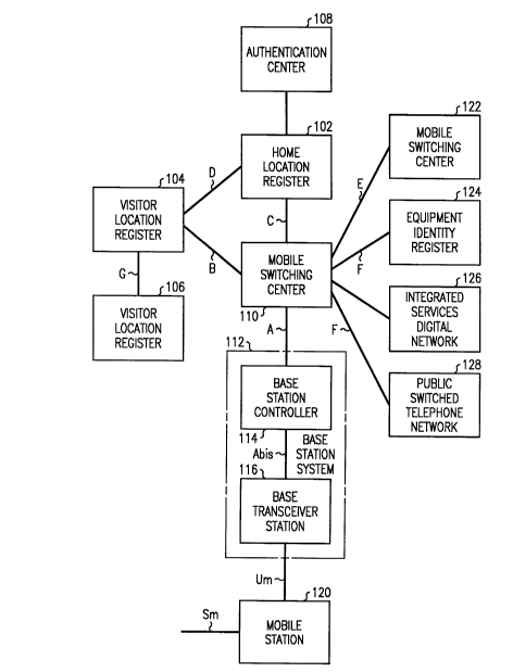
FIG. 1 is a block diagram of the basic GSM model of a mobile
swilching center and its direct and indirect inte~ r~ces,
FIG. 2 illu~ tes how this model is implçmente~l in one exemplary
35 embodiment;
2078197
FIG. 3 illu~ es the various signaling protocols used for ~ign~ling
messages in mobile telecol~-n,~ tions ~.y..Lems;
FIG. 4 illustrates the interconnections among mobile stations, land-
based stations, base station ~y~.~cllls, the public ~.wilched telephone network, and a
5 mobile ~;.wilchillg center;
FIG. S illustrates the physical paths used for si n~ling and for voice or
data interco~ ections;
FIGS. 6-8 illustrates the si~n~ling illt~,..;ollllections including the role of
the wireless global switch module (WGSM);
FIGS. 9-13 illustrate the process of est~bli.~hing a mobile to land call;
FIG. 14 illustrates the release of a mobile call;
FIGS. 15-18 illustrate the handover pl~)cess;
FIGS. 19-21 illustrate the handover process in terms of mçss~ge
eYçh~nges;
FIGS. 22-28 illustrate an inco~ lg call to a mobile station.
Detailed De~ tion
FIG. 1 is a block diagram of the reference model for the Eul~peall
standard, the Global Systems for Mobile Col,,,,,.~nication~ (GSM). Each of the lines
interconn~cting blocks of the ~ ~m that is i~Pnfifi~ with a letter, has a GSM
20 standard speçifiYl i~ . r~e Briefly, the ~ull~ose of each of the blocks is the
following:
The Home Location Register (HLR) 102 cont~in~ data for a mobile
~;u~7lul~r. The data stored in the HLR is the perm~n~nt data that is inr3eperl~ent of
the cuslum~.'s present location, plus le.ll~ol~y data such as the addresses of Service
25 Centers which have stored short mess~ges for a mobile station. (An example of such
a message is a request to turn on a "voice message waiting" lamp in~ ting that avoice message has been stored for the mobile station user in a voice m~ ing
system.) These addresses are erased after the short m~ssages have been delivered.
The HLR also in~1icates the Sign~ling System 7 point code used to find a module that
30 contains the Visitor T ocafion Register (VLR) 104 cull~inlly ~csoci~te~l with the
mobile station.
The VLR COlll~iIIS current data for each mobile Cll`lOI~-f,l, including that
customer's mobile station's present or most rece.ltly known location area, the
station's on/off status, and seuulily pal~clel~7. A remote VLR 106 connected via a
35 G interface is also shown.
2078197
The ~llth~onti~ation center (AUC) 108 provides authentication and
encryption p~me~el~ to ensure that a mobile customer cannot falsely assume the
identity of another mobile cusl~nl~,~ and provides data for encryption of the voice or
data, and control signals tr~n~mitted via the air ~ecn the mobile station and a
5 serving BSS. The GSM lerclence model prescribes digital co~ ;on over the
radio ch~nn~l~. Since it is possible to listen to these radio ch~nnel~, encryption
beco...es desirable for the link bel~,en the mobile station and the radio transceiver at
a base station serving that mobile station.
The Mobile Switching Center (MSC) 110 is for switching calls
10 involving at least one mobile station.
The BSS 112 comrri~es a base stadon controller (BSC) 114 and one or
more base transceiver stations (BTS) 116 for co.~....-.nic~ting with mobile stations
(MS) 120. The BSS and the MS co....~ icate via radio conn~ction~. The BSS is
also connecte~l via trunks to carry the voice or data, and control msss~s between
15 the mobile stations and the MSC. The BSC and BTS may be in dirrel~enl physical
locations (for example, the BSC may be co-located with the MSC) in which case a
trunk is le~uilcd to int~l~;ollllecl the two. S m represents the human int~façe to the
MS.
The equi~l.ltnl identity register (EIR) 124 retains a record of ranges of
20 certified e4ui~lllcllt identific~tions and ranges of or individual eq~ . nt
i~lentific~tions which are under observation or barred from service. The e4uip~llcllt
i-l.ontifi~tion inr~ lalion is received from a mobile station at the mobile ~wilchillg
center. The EIR is used to verify that the e luip~nl number of the MS is certified
for use in the public nclwul~ and is not on the observation or service barred list.
Mobile ~wilchhlg centers are ct nnecte~l to other mobile ~wilchhlg
centers, direcdy or via the public ~wilched telcphone network 128, to the publicswilched telephone nctw~ for ~ccessil-g land-based customer stations and to
integrated services digital network (ISDN) nelw~k~ 126 for co..~ -icating
according to the plolocols of ISDN.
While the standards specify the functions of each of these blocks, they
do not specify how each of these blocks is to be implemente~ It is the purpose of
this description to illustrate one arrangement for ;mplem~nting these standards in an
advantageous malm~.
FIG. 2 illusl~ales the system ~ucllhc-clulc for imple.~.. nl;ng a GSM
35 mobile co.r,...~ ication system. The mobile station (MS) 202 co.~ nic~tec with
the BSS 204 over radio links 206 using optionally ellc;ly~lcd digital radio
2078197
- 5 -
co~ ationS for the voice or data, and control connections between the MS andthe BSS. The MS co.. ~ ir~tes via the BSS with the mobile ~wilchillg center
(MSC) 210. The BSS and MS exchange control mess~ges with the mobile switch
center using the CClTT sign~lin~ system 7 protocol (SS7).
S In this arr~ngçm~nt, the HLR 212, VLR 214, AUC 216 and EIR 218
records are all integrated into the MSC 210. When an MSC needs the HLR, VLR,
AUC or EIR records from another nclw~lk entity, it obtains them via SS7 messagestr~n~mitted to the entity that cull~,ntly holds this inf~~ ion.
The MSC co-.. u-.i~tes with a billing center 220 for ~ccum~ ting
10 billing records using the CCITT X.25 protocol and also co.. -;cates with an
Operations and M~intçn~nce Centa (OMC) 222 using the CCITT X.25 protocols.
The OMC co.-~.. -icates with BSSs via the MSC using SS7. In one
imple.. ~.nl~;on, the OMC co.. ni~a~es with a customer ~dmini~tradon system 224
using a standard RS-232 link. In a~l-litiQn, .~inten~nce messages between the BSS
15 and OMC are ~ ~l using SS7 with the Base Stadon System Operadon
Mailllcna~lce and Administradon Part (BSSOMAP) protocol.
Sign~ling System 7 is descr~ in detail in A. R. Modarressi et al.:
"Sign~ling System No. 7: A Tutorial," IEEE Col~ rations M~ ine, July 1990,
pages 19-35. The GSM standard protocols are specified in the GSM ~ldard
20 specificadons, which at this dme is in version 3.8.
FIG. 3 is a diagram of the protocols used in dirr.,.~ types of
co.~-.. -i~tion~, acc~,ldillg to the GSM standard. Most of these protocols are those
of SS7. Of the seven layers of the protocol accordillg to the Tntç.rn~tional Standards
Org~ni7~tiQn (ISO) layered m~ss~e protocol, only the top (applicadon layer) and
25 the bottom three layers (Network, Data and Physical) are shown on the left. Four
types of mes~ges are shown: The first double column inclll-les those from
~wilchillg system to swi~hillg system for land-based trunks including either a
telcpholle user part (TUP) or an ISDN user part (ISUP) (both SS7 standards) for the
applicadon layer. The second column is for m~.s~ges among MSCs, VLR, HLR and
30 EIR which messages use the SS7 standard Transaçtion Capabilides ~TC),
Transacdon Capabilides Applicadon Part ICAP) and Mobile Applicadon Part
(MAP) sublayers of the appli~ation layer (MAP is enh~nce(l with GSM standards).
When dhese mess~ges are stricdy in~.rn~l to dhe MSC, these protocols are simplified
and messages tr~n~mitted directly or via protocol handlers between the responsiblè
35 processors. The third column is for co.. ~ni~ations between the mobile swilcllillg
center and a BSS. The final column is for co.. ~.. ~ir~tions bel~ the mobile
2078197
- 6 -
~wilching center and mobile station.
The three bottom sublayers of the protocol (layer 1, the physical layer,
layer 2, the data layer, and sublayer 3, the message tl~~ L part (MTP) sublayer, a
sublayer of the network layer) are identic~l for all of these types of co~ iç~tions
5 and are in accordance with the SS7 Message Transport Part (MTP) standards of the
CCITT Q.701 - Q.707 standard. The Sign~ling ConnPction Control Part (SCCP), a
sublayer of the nelwull. layer, also a CCITT standard Q.711-Q.714, is connectionoriented for the MSC/MS co....~ tiQn~, is connectionless for the second column,
and may be either for the MSC/BSS co.~ tions. SCCP is available for some
10 ISUP appli~tions For the first column (switch to switch) the TUP and ISUP
appliç~tion layer co~ n~nicates directly with MTP 3 sublayer of the 1~IWO1k layer.
Cu~ -icPtion~ bel~eel the MSC and either the BSS or the mobile
station use a Radio Sub~y~lt;m (Base Station System) Appli. ~tion Part (BSSAP)
protocol. For co....-~....ic~tion~ between the mobile switching center and the BSS,
15 layer 7 uses the protocols of the BSSAP in~ ling a Base Station System
Management Application Part (BSSMAP). The co~unications bel~. ell the
mobile ~wilcl~ing center (MSC) and the mobile station are p~lrJll~d in the protocols
of BSSAP inchltling a Direct Transfer Application Part (DTAP). BSSAP, including
BSSMAP and DTAP are GSM standards.
FIG. 4 is a basic block diagram of a mobile switching center 400
(switch), as imple.~ nled using AT&T's SESS~) Switch. The switch, described in
detail in The AT&T Techni.~l Journal, vol. 64, no. 6, part 2, July/August 1985,
pages 1305-1564, (Journal) includes an ~rlmini~trative module 402, a co..~ -ic~tion
module 404, and a group of ~wil~;hing mo~ les 406-412. The ~wilching mo lnl~s
25 applicable in the GSM n~lwoll~ are of four types; a wireless switching module(WSM) 406 for co.. ~ cating with BSSs, and also optionally con~.. ~icating with
the public switcllul telepholle network (PSTN); switching modules (SM) 408 for
CO.... icdlillg with the PSTN; a wireless global switch module (WGSM) 410 for
serving the sign~ling co.-.... ~lic~tio~ needs for controlling calls involving mobile
30 stations; and a PSTN Global Switch Module (PSTN GSM) 412 used if PSTN trunks
are of ISUP or TUP types, i.e., use SS7 for sign~ling to the PSTN. The PSTN GSM
pr~cesses ISUP or TUP protocols and can optionally also be conl-e~t~A to PSTN
trunks.
The functions of the ~-lmini~ tive module (AM), co....n...-ic~tions
35 module (CM) and ~witchil~g module (SM), in relation to the PSTN are essentially as
described in the referenced Journal. The purpose of the WGSM, as described
2078197
- 7
hereinafter, is to simplify the .cign~ling co.. ~ tions between BSSs and the
WSM serving calls for the BSS, and ~I-.~n the MS and the WSM. The PSTN
GSM is for controlling cc,mllloll channel si n~ling between the MSC and the PSTN.
The PSTN GSM is connecte~l by message delivery paths to protocol handlers in theS SMs.
The ci~n~ling aç~ clule of the mobile switchillg center is cjgnifi~ntly
simplified by having cjgn~ljng messages go through a col lon set of data ~witches
and protocol handlers in a wiieless global swilclling module (WGSM). Physically,the wireless global ~wilching module is connected via nailed up ch~nnel~ (message
10 delivery paths) ~wi~ched through the time multiplexed switch of the co.,....ll..ir~tions
module to each of the wireless ~wit;hing m-ylnlçs These are 64 kilobit ch~nnel~,the same as the PCM voice ch~nnel~ of the 5ESS switch cc,.. ~ tions module.
Over another nailed up physical channel col-necl;ng the WGSM with a WSM
mÇscqges are sent for a BSS via virtual channels in that physical channel; other15 virtual channels of that physical channel carry messages that ori in~te from or are
destined for the mobile st~tions
The wireless swilcl~ing modules (WSM) are combined packet and
circuit ~wil~;hillg modllles each compri~ing a swilching module processor (SMP), a
packet ~wilchillg unit (PSU) comrri~ing a plurality of protocol handlers
20 inl~,~ol~lected by a local area n~ Iwo~k, and circuit ~wi~chillg arrang~ nL~ including
a digital facility interface a)FI) and a time slot inttir~ ge unit (TSIU). The TSIU
is connecte~l to a time multiplexed switch of the co--..~ ic~tionc~ module for
int~ l~;ol~lccLing the ~wi~;hi~lg modnles Switching m~ les comrricing a packet
~wi~chh~g unit are disclosed in M. W. Beckner et al.: U.S. Patent 4,592,048.
The cign~ling paths bc~.e~ the BSS, WSM, and the wireless global
~wi~ching module (WGSM) are as follows. Each base station is connecte~l by digital
carrier facilities to two or more of the wheless switch mod~lles 504 (FIG. 5). Many
of these digital f~ciliti~s include one or more .si~n~ling ch~nnçlc~ the ~ign~ling
channels from each BSS being connected to at least two WSMs. The sign~ling
30 channel is connP~ted via the digital interface of this wireless switch module 504 into
the TSIU of the wireless switch module and is thereby connecl~l through the
co.. ~.. -ication module 506 and to a protocol handler (PH) in the wireless global
switch m~llle The wireless global switch module protocol hanfllers are
in~l.;olmected via a local area nclwul~ in the packet switch unit of the WGSM.
- 2078197
- 8 -
The portion of the ~ignAling path between the WGSM and a destination
wireless switch module is as follows. The WGSM has at least one protocol handlerwith a port for L~ .;LI;ng messages to and r~eivi~lg m~ssAges from a specific
wireless switch module. This port is connected to a m~ssA~e delivery path that
5 passes via a nailed up connection through a time multiplexed switch of the
cc,.. ~-ic~tions mr~ . Each such mecs~ge delivery path is a 64 kilobit data linkand is connected to a port of a protocol handler at each end. In case of a failure of a
protocol handler at either end, spare protocol handlers can be used to replace the
failed protocol handlers. The protocol handler in the wireless switch module
10 co....--..ni~Ates on its local area network side via a packet interf~ace with a ~wilchillg
module processor of the WSM. This switching module processor p~rOl.l-s call
proces~ing and generates or proces~es, for example, the BSSAP portion of a message
between a WSM and a BSS. The mess~A~ge delivery paths and the physical signAlingdata links interconnecting a BSS and a wireless switch module carry a plurality of
15 virtual data paths, usually, ~ )ol~y virtual data paths (SCCP connection~)
A~sociAt~ either with a mobile call or a mobile service such as a location update.
These sign~ling arran~ have a number of adv~ntAges. By having
at least two ~ignAling data links bel~eell each base station and at least two wireless
switch mo~ les, re-3,..--1~ncy is gained and operation can continue even if either of
20 the si nAling chAnne-l~ (inr~ din~ the protocol hAndlers at each end of a sign~ling
channel) or a WSM fails. The use of a single wireless global switch module with
inherent sparing of protocol handlers conc~ lates the trAn~lAtion infi)rmAtion
required to select a r1estinAtion wireless switch module when, for ~ le, VLR data
for a particular cu~lo~ as if lentifie~ by that cu~lo...- - 's T~le....~lional Mobile
25 Subscriber Tdenfifir~Atir)n (IMSI) is required. Failure of one or more of the protocol
handlers in the WGSM can be ove~ollle by replacing a failed protocol handler with
a working spare and by pro~lly initiAli7ing that protocol handler to take over the
f~ln~tio~ of a failed protocol handler. Local leÇelence num~~ 3i~ se~1
hele;nar~er are used to identify SCCP connections. As described hereinafter,
30 b~duse key inro.malion is stored in the local reference nu-~b~ , and because
duplicate records are ..~in~ y1 on all stable SCCP connec~lls through protocol
handlers of the WGSM, none of these connections are lost even though they may
have been served by a failed protocol handler.
The WGSM has at least one spare protocol handler per shelf of a PSU.
35 In the event of a failure of any protocol handler, a spare takes its place. If no
red-ln~lAnt data were available, then in the event of a simplex failure in a protocol
2078197
handler the dynamic data regarding SCCP connections would be lost and
consequently all BSSAP calls switched through that protocol handler would be lost.
R~ m~l~ncy of this data is added to the software architecture to ensure the integrity
of this connection data.
When a comleclion is set up between a mobile swilching center and a
BSS, a local connection i~l~nfifier is associated with each distinct conlleclion. In
order to keep each instance of the comleclion coordinated bel~een the MSC and the
BSS, this connection inf~lllation is shared through the use of SCCP local rcr. rence
numbers. According to the CCITT SS7 protocol, each end will send its local
10 reference number and the far end's local l~Çe~llce nulll~. when first con~ -;ng the
setup of a valid connecli. n Subsequent dialog le luircs the sen~ling of the far end's
local lGr~cllce number. The value of this local reference nu~llb.,l is not constricted
by standards. When a connection is first initi~ted in the mobile ~wilching center, the
local reference number is çncodçd to include a connec~ion identifier and the number
15 of the protocol handler on which the connection resides.
The MTP layer provides for load sharing on a data link, changeover and
changeback, with the possible result that inCominp m~ss~ges for a com e.,lion may
arrive on a dirÇ~.~,n~ physical link than mess~gss being sent. When this occurs, the
SCCP message arriving in a dirre.ellt protocol handler is routed to the proper
20 protocol handler by decoding the local reference number since that 4U~lti~y contains
the idçntifi~tion of the protocol handler (PH) upon which the comleclion resides.
Whenever a SCCP comlec~ion goes into an active (stable) state, this
connection inrollllalion is shared with the next A~cçncling PH in the PSU c~"...~ n;ly
(wL~Ie;ll the first PH is the "next ~cçn-ling" PH for the last PH). This "next
25 ACcen~ g" PH is known as a "backup PH." When a PH fails, a spare PH is swilclled
into its position and thereby connectcd to the sources and destin~tions of messages
for that PH. The "next ~cçntling~ PH transmits to the spare PH a list of reference
numbers of stable connect~iQns from the failed PH; the "next ~cçnding" PH will
continue to control these connections as long as they are active. The spare PH
30 assigns local lefcl~llce numbers for new connectlons that have the same logical PH
number as the connections formerly served by the failed PH. When the spare PH
receives a mess~ge for an active conn~l;on~ it first checks to see whether the
crc~ince nulllb~,~ is one of a connection controlled by the "next ~cen-ling" PH. If
so, the spare PH transmits that message to the "next ~cen-ling" PH which has the35 illfollllaLion for p~cesshlg that message, and which thererolc can IIIAin~Ain the
virtual comleclion. In this way in the event that a PH fails, messages received on
2078197
- 10-
eYicting SCCP connections for the failed PH are ~ulo.n~;c~lly routed to the "next
~Ccen~ling" or backup PH. When a PH fails, the backup PH will au~.~ ;c~lly restart
timers associated with the SCCP connections from this backup ihlfc,l,llalion. In this
way, stable connections will remain stable as will calls dependent on those
S connections. Every PH, that sets up SCCP connections, has a ~ ic~te~ backup PH.
Since a spare PH then ~cc~lmes the logical role and name of the failed PH and
accepts new SCCP message connection requests for that PH, this will gradually
reduce the ~ )O~ overload on the backup PH. When the failed PH is eventually
rci,lolcd to service, it then takes the role of a spare PH.
While in this embo l;.nt.u, the "next ~Ccen~ling" PH is used as a backup,
any other pre~Pte~ ntA backup arr~ngement, such as the "next ascending
skipping 1" (in a system with an even null.~. of active PHs) could be used instead.
The term "predet~rmint~ a~j~çent" is used to describe any pre~cte....;I-ed backup PH
selection.
As di~ ssed above, when the spare PH ~.. u.. es the role of the failed
PH, the backup PH will report the present status of all its active connections to the
spare PH. The spare PH will not reuse lesow~;es, such as connection i-lentifier
numbers, for active connections still running on the backup PH when setting up new
SCCP conn~ctionC. The backup PH will then con~inue to service all presently active
20 conne~;!;onC until they are rele~1, as well as servicing new SCCP connections for
itself.
When a mobile station is first pow~led up within a s~ii~ied mobile
n~,hvolL, the intern~tiQn~l mobile subscfiber irierltific~tion (IMSI) is used by the
mobile station to identify itself. This IMSI is used to route a request for VLR data to
25 the WSM that COnkLillS that data. Each protocol handler of the WGSM contains a
table that stores the IMSI-WSM map, the table being created from data supplied by
the WSMs. In orda to allow HLR and, where possible, associated VLR records to
be stored in any WSM, this look-up table has one entry per IMSI. During the
l~tion update or registration process, the SM that stores the VLR data will
30 ~soci~te a Te~u~ol~y Mobile Subscriber ~dentification (TMSI) with a mobile
station. The TMSI, whose value, while at least in part random, is not otherwise
const~te{l accor~ g to the GSM standard, is specially encoded with the identity of
the WSM (i.e., a switchillg module having wir~less sOf~ ) that contains the VLR
so that acces~ing the proper WSM for incoming mPss~gçs when VLR data is
35 required is simplified if the TMSI is available. Randomness of the TMSI is
m~int~ine~ by r~ndQmi7ing three of its four octets. Except on initial mobile station
2078197
11
power up, as desçfibed above, the TMSI will n~rmQlly be used for all BSSAP
transactions. When a mobile station initiQtçs a transaction (such as a call or location
update), the SCCP connection data base that stores inro~ ion about the transaction,
also stores inrc,l.llation to identify the WSM that contains VLR data as well as the
S WSM that contains the trunk connçcted to the BSS. This is used for the routing of
all subsequent m~Ss~Qges for this connection~ which contain no TMSI.
As an çxQmple of the operation of the 5ignQling system, consider a data
comlec~ion ~l~een a BSS and a mobile ~wi~chillg center. Assume that the
comlecLion is initiQte~ in the BSS. An initial mÇssQge would first be transpolLed by
10 MTP in the BSS from the BSS over a signQling data link logically inte~connecting
the BSS and a WGSM. The protocol h~n~ller~ in the wi-reless global switch module,
which tçfminQtçs the signQling data link passes the mÇscQge from MTP to a SCCP
control program. This SCCP program StfipS off the MTP header and parses the
mÇssage~ Depending on the conterll~ of the message, a connçction is established or
15 releQced, or the transfer of data is required. In this example, com e~-Lion
establichmçnt is requested and a SCCP connection (i.e., a virtual CifCUit) is
te,l~ h~ily set up ~L~,ell the protocol handler in the WGSM end of the signQlingdata link and the protocol handler in the BSS. The SCCP control program infol.lls a
base station system application part (BSSAP) (also rerell~d to as a radio sub~y~e
20 application part in FIG. 3) of the request for a connection establichm~-nt via a
primitive int~rf~Ge~ BSSAP then parses the BSSAP message and obtains the identity
of the ~lestinQtion wileless switch modllle~ In the case, for example, of a query
~equi.illg VLR data, this ~lesfinQtion WSM is idçntifi~A by the i~ . ..hl;onal mobile
subscriber identity (IMSI) field contained in the BSSAP m~ss~Qge The BSSAP
25 control process uses the IMSI to index a look-up table to find the WSM where the
VLR data base for this IMSI is to be found. The m~CC~ge is then sent within the
WGSM from the protocol handler terminQting the signQling data link to a protocolhandler that tçrminQtes a mçssQge delivery path to the identified WSM. This
protocol handler then sends the message to a protocol handler on the destination30 WSM which in turn folv~ ls the message to the ~witching module processor of that
WSM. A BSSAP cont-rol process in the destin~tion WSM then further parses the
meSs~Q~ge and passes it on to a call processing p~l~ for pl~cessing a mobile call or
service.
Another example of the ci~nQling procelul~s carried out in this
35 embo.lim~nt of the invention is the procedure for sending a message from a wireless
switch module to a BSS via an established connection. In the trQncmitting wireless
2078197
- 12-
switch modlllç, a BSSAP process assembles a BSSAP layer of the message that is
tagged with the local reference nw~ identifying the SCCP connection. This
process then fo~wd~s the message to a protocol handler in the source wireless
switch modllle, which then transmits the mess~ge over a nailed up message delivery
5 path going through the co.. ~nic~tions module to a first protocol handler in the
wireless global switch module. This first protocol handler eY~mines the local
rercl~"ce number of the mçss~ge and uses this to dete ..-;~-e the second protocol
handler that ~e- ...in~lf,5 the SCCP connection. (This local lerer~l1ce number was
previously derived during the process of establishing the SCCP connection.) This10 protocol handler then uses a SCCP process to encapsulate the message with a SCCP
header and passes the mf ss~ge to a message t ~lspol l part (MTP) process for adding
the MTP hf ~lers The mf ss~ge is then sent over the (logical) data link to the BSS.
(The physical data link coll~*)onding to this logical data link has been described
earlier.)
Advantageously, this type of arr~ngement permits essenti~lly all of the
SS7 protocol h~n-llin~ functions to be carried out in the packet ~wilchillg unit of the
WGSM (without involving the switching module processor of the WGSM) and
allows the tr~n~mitting and receiving WSMs to process their mess~ges independentof the destin~tion Effectively, the set of protocol h~n-llers of the packet switch unit
20 of the WGSM acts as the handler of all sign~ling protocols. (A .~ lly equipped
WGSM con~ins 75 active and 5 spare protocol handlers.) The WGSM assembles
and disassembles the Sign~ling System 7 headers to the application data of the
m~ss~ges and swik~hes the messages for tr~n~mi~ion to the proper WSM which may
either accept the messages (if the destin~tion is the mobile ~wilchillg center) or
25 origin~tes mess~ges to the a~plopllate BSS (if the destin~tion is either a BSS or a
mobile station).
In ~ iti~n~ the MSC co---.. ,lic~tes from the ~rlmini~trative module
with an external service center 224, using the X.25 protocol for delivery of short
meSs~ges~ such as an indication of a voice m~ssage waiting. The MSC
30 colllmu-licates with the public switcl-ed tele~hol~ h. Iwolk using a land-based
sipn~ling system such as SS7.
The ~wilching mo~llles also co..~ -icate messages via the message
switch of the con~ nication module as is done in a land-based SESS switch. Call
processing mes~ges~ such as the messages that are exchanged in order to set up a35 connection through the co.ll.~ ications module ~Iw~;e~, for example, a switching
module connecte~1 to the public switched telephone network portion of a land-to-
2078197
- 13-
mobile or mobile-to-land call and the wireless switcl~illg module that is com e~ d
via the BSS to the mobile station end of the call, are sent in this way.
Whenever an MS is in the region served by its home MSC, i.e., the
MSC that contains the HLR for that MS, the base VLR is attached to the HLR in
S such a way that CO~mOI data is stored only once for the two registers; the VLR and
HLR are then stored in the same mo~111e
When the mobile station is either in the power-off state or in the power-
on state but not in any active call state, only a base version of the VLR is ~ in~ A
for that mobile station in the VLR WSM. When a call is originated by a mobile
10 station or a call is received for that mobile station, a separate dyll~llic version of part
of the VLR is stored and ...~inl~in~A in the WSM that controls the mobile calls. This
copy of the VLR is linked to the termin~1 process in that WSM that controls the
mobile station end of the call. If the mobile station moves and the call is handed
over to a di~r~.~,.-t ~wilchillg mo~111e, then the dynamic copy of the VLR is
15 transferred to the new WSM serving the mobile station for that call and is linked to a
t.ormin~1 process for serving that call in that WSM. Note that the data in the base
VLR that is not relevant to the MS locations is changed only by a~lmini~trative
actions or such Cu~Lulll~. pro~,..n...;ng actions as the specification of a callfolwdlding number and are not copied into the dynamic VLR. When necess~..y, the
20 system ~fimini~trator m~lifies the HLR which in turn updates the base VLR; the
a~lmini~trator has "read only" access to the base VLR for trouble shooting ~ul~ses.
The ~ tion of the mobile station is not 1lp~te~l in either the dynamic
or the base VLR during a call, and is up-lated in the base VLR only as part of alocation update plvcedul~ tion update prùcelul~s are carried out when the
25 mobile station is idle with power on, and moves from one location area to another.
A location area is the area that is paged when a call te....i~ ing to an MS is received.
All incon~;n~ calls first check the HLR. This is because the HLR is
fixed and the 1Ocation of the HLR record is tied to the called IIUlll~ di~ ,Lul,y
nulll~r) of a mobile station. The HLR has stored within it the inr~ ;on necess~ry
30 to find the base VLR; this inrollllaLion includes an identificafion of the mobile
~wiLching center that cont~ins the base VLR. For this ~et~ descl;~Lion, this MSCis the same as the MSC of the HLR, and the HLR and VLR are stored as one block
so that if either is located the other is also located. All a~lministrative changes of
data associated with a mobile station are entered first into the HLR which then sends
35 mess~ges for entering the coll~sl)on ling change in the base VLR. CusLolller
initi~ted changes such as the plesclil)Lion of a dirr~.~.lt call folw~ding number are
2078197
- 14-
forwarded initially to the base VLR which does not initially make any change in its
record but fol ~ards the request to the HLR which makes the necessary change andgenerates a message for updating the base VLR. The HLR is accessible via the
mobile station directory number or the Tntern~tional Mobile Subscriber Tdentific~tion
5 (IMSI). The VLR is accessible via the IMSI or the TMSI; the HLR can also access
the VLR by a special ISDN address. ISDN addresses are m~int~ined for VLRs,
HLRs, MSCs, and EIRs according to the GSM specification.
The VLR is attached to the HLR so that comrnon data need only be
stored once. This arrangement is satisfactory as long as the mobile station is in the
10 region served by the MSC; consideration of the storage of the VLR when the mobile
station leaves that region is beyond the scope of this description.
The combined HLR and VLR is stored in the wireless switching
modll1es of the MSC. Each switching module stores records for a range of mobile
dil~clUl.~ numbers and each module has a range translation to select a module based
15 on the directory number. Since the HLR/VLR must also be accessible via the IMSI,
a table is stored in each protocol handler of the WGSM to identify the module that
has stored the VLR/HLR for each IMSI served by the MSC. No translation is
required for access via the TMSI since that contains a subfield for identifying the
VLR/~R modules.
FIG. 5 is a block diagram illustrating the physical signaling paths
between base stations and wireless switching modules. The base stations 502 are
connected through pçrm~nçnt virtual circuits which physically pass through a
WSM 504 serving the base station and through the co"""~nications module 506 to aprotocol handler in the WGSM 508. The protocol handler receives messages in the
25 SS7 protocol used to co~ llullicate with the base station and transmits the message
to the correct WSM; the digital facility interface connected to the BSS transmits the
messages to a protocol handler of the WGSM which is connected by a switchable
physical nailed up data channel to the destin~tion WSM, where it terminates on aprotocol handler which is connected to the switching module processor of the WSM.
30 Advantageously, the WGSM termin~tes a standard protocol and allows any WSM tocontrol any calls from the base stations that have trunks to the WSM, since the
processor of the switching module (SMP) for controlling the call need not be theSMP for controlling a specific connection between a BSS trunk and a channel to aCM or to another output of the WSM.
- 2078197
- 15-
FIG. 6 shows the logical ~i n~ling system. The base station system 602
co~ tes with the WGSM 604 which then delivers its message via the
cc,."mu.lications module 506 to the app-u~l;ate WSM 610.
As shown in FIG. 7, the VLR data for a particular mobile ~wilching
5 center is spread out over the WSMs 702,...,704 in that center. In the particular
example, when WSM 702 needs VLR i,lr,. ..-nl;on from WSM 704, it requests the
info. ~1 ;on via the call prûcess;ng inter-module data links switched through the
message switch of the co.. ~l-iç~tions modllles of the SESS switch.
FM. 8 illustrates the modllles involved in a mobile-to-land call. The
10 base station system 802 nearest the mobile is connected by a voice path to a wireless
switching module (WSM) 804 which is connectable through the cG.. ~ tion
module (CM) to another ~wilchi-lg module for COnlleCli~n via the public ~wik~lled
tclephone network (PSTN) 808 to the called customer. The PSTN global ~wilcl~ g
module (GSM) 810 is used for controlling SS7 sign~ling to the public ~wilched
15 telephone nelw~l~. The WSM 812 that conlaills the base VLR data is connected via
virtual data links to the WSM 804 controlling the mobile station leg of the call . The
SM 806 and WSM 804 are conn~,cte~l by a virtual data link in order to coordinate the
activities of the termin~l process h~n-lling the call in each of these modules. The
WGSM 814 co------~ tes all data to and from the BSS and tlansn~ils it as neceS
20 to either the WSM 804 or the VLR-WSM 812.
Con~i~tent with the principles of operation of the SESS switch for land-
based calls, the ~ .n~;~e module 508 (FIG. 5) is used for selecting outgoing
PSTN trunks on mobile ori in~tyl calls and for selecting time slots for voice paths
bcl~en ~wilching mtxl~ s In addition, the ~-lmini~trative module is used for
25 selecting a trunk b~ .,n the mobile ~wit ;hillg center and a base station controller.
The base station controller selects a path bel~e~n the incoming trunk to the base
station controller and the base transceiver station. As previously in-lic~te~l, this path
may be a land-based trunk. The trunks belwe-,n the BSSs and the mobile swilchingcenter are one way outgoing from the mobile swilching center. This makes the
30 finding of an idle trunk from the cenh alized ~ . .i n;~ e module efficient and
allows the trunks to be fully ~lhli7e~ whether the call is or~gin~te~l by a mobile
station or is t~-rmin~t~d to a mobile station, the trunk will be hunted for and ~lloc~ted
by the ~lmini~trative module which is a part of the mobile swilching center.
FIGS. 9-13 illustrate the messages required in processing a mobile-to-
35 land call and shows the source and destin~hon of each message. The call is initi~tedby a control Gh~nnsl request m~ss~ge 902 (FIG. 9) from the MS to the BSS to
2078197
- 16-
request the assignment of a de~ ate~l control channel for further si~n~ling from the
MS. The BSS responds with a control channel a~cignment message 904 to allow the
MS to access the proper control channel. The MS then transmits a service requestmçss~ge 906 to the BSS which passes this service request message 908 to the
5 WGSM. The WGSM transmits a process access request m~ss~ge 910 to the WSM
that contains the VLR information. The WGSM has the data for dele~ g which
WSM contains the VLR illfc,~ Lion for this mobile station. This data is used when
the TMSI is not available. If the TMSI is available, it has the VLR-WSM ID
encoded in it for easy ~ ntifi~tion of the VLR-WSM. The mpss~e from the
10 WGSM to the VLR-WSM is for processing the service request and for creating the
connection data in the VLR-WSM for the request. The VLR-WSM enters a tuple in
the connection data block for the process that handles the request. The data includes
the identifin~tion of the connection tr~ns~ction using the connçction An
allth~nti~tion process, if needed, is initi~ted by the VLR-WSM, which transmits a
15 m~ss~ge 1002 (FIG. 10) to the mobile station (the m~s~ge is actually ~ n~ ed via
the WGSM, the WSM connecte~ to the BSS, and the BSS) to request ~llth~ntic~tion
algc,lill~ c~ tion The mobile station responds to the VLR-WSM with a
meSS~ge 1004 cor~t~ inf~ the result of the ~ h~l-t;cation algclilhm calculation. Meallwhile, the VLR-WSM l,~nsl~its a message 1006 to the
20 ~lministrative module (AM) requesting the a~ignment of a BSS trunk for the call
and the AM ~ a m~s~e 1008 to the WSM connected to that trunk for
creating a wireless origin~ting termin~l process in that WSM for h~n~lling the call.
The WSM then returns a mess~ge 1010 to the VLR-WSM for notifying the VLR-
WSM which trunk WSM (i.e., WSM conl-eclcrl to the trunk to the BSS serving the
25 call) and BSS trunk has been ~igne~ to the call. As will be seen below, the VLR-
WSM is ~uil~d for controlling the ciphelillg inrol~alion for the call.
If cirh~- h~ is used, the VLR-WSM transfers (mçss~ge 1102, FIG. 11)
to the WSM for h~n~lling the call, a copy of the call l,lvces~ing related infollllalion,
relating to the mobile station from the VLR record to the call controlling WSM. If
30 ciphering is used, the VLR-WSM ~l~ sr.,l~ the cipher command to the BSS via the
WGSM (mçss~ges 1104 and 1106). The BSS ~ slllils a cipher mode comm~n-l
(message 1108) to the mobile station. The mobile station then sets up the ciphermode and tr~n~mit~ back to the BSS, a cipher mode completed mçss~ge 1110. The
BSS sends a message to the VLR-WSM that the cipher process has been
35 completed 1112. At this time, both the BSS and the mobile station are in a
corresponding cipher mode. The details of the enciph~-rm~-nt are specified in the
2078197
- 17-
GSM standard.
The mobile station then sends a setup request m~ ge (1114 and 1116)
via the WGSM to the call controlling WSM (i.e., the WSM that contains the termin~l
process for the mobile station). The WGSM had previously been informed of the
5 identity of the WSM in mçssflge 1104. The WGSM checks to ensure that no failures
have been encow,tr,.~d up to this time before call setup request. If any failures have
occurred, the failures are repol~ed to the WSM. The WSM then transmits a
message 1118 to the mobile station inrlic~ting that the call is procee~ling
Next, if the e~lui~ nl v~ lfltion function is nee.1e 1, the VLR-WSM in
10 cooperation with the call controlling WSM and the mobile station ~lÇvlllls that
function. (E4uipm~nt validation is optional in GSM according to the wishes of the
teleco~ nic~tions op~ alOl.) The VLR-WSM requests (message 1202) the mobile
stadon to furnish its Tnt-orn~tional Mobile Equil)m~nt Td~ntificadon (IMEI). Themobile stadon responds with its IMEI (message 1204) to the VLR-WSM which
15 checks to insure that the mobile stadon is authorized to use the neLwvl~. The VLR-
WSM sends the result of its check (mess~ge 1206) to the call controlling WSM.
Meanwl,ile the trunk WSM nodfies the BSS of the idendty of the previously
~ignç~l BSS trunk (m~ss~ge 1208). The WSM also requests that the BSS pick a
radio channel for the voice (or data) cvlll~ lnic~tion with the mobile station. This
20 radio channel will then be ~sociflte~1 with the A~signç~l BSS trunk for the length of
the call or undl the call is handed over to another BSS or t~-- ...inA~ç l The BSS
assigns the radio channel and nodfies the mobile stadon of the A~si~nm~-nt
(m~Ss~ge 1210). The mobile stadon responds (message 1212) when it has received
this assignment and has tuned its radio to that ch~nnel The BSS then reports back to
25 the WSM that the radio channel A~si~nm~-nt process and the radio to trunk
conneclion have been completed (message 1214). The WSM requests
(mÇssA~e 1216) the ~lministradve module to hunt for a trunk to the public switched
tcle~hone l~lwolk for compledng the land part of the call and the fl~lmini~tradve
module assigns this trunk and requests the ~wi~cl ing module connected to that trunk
30 to create a termin~l process for the call (messflge 1218). The ~wilching module then
transmits a m-o~sflge 1220 to the WSM that the network connecdon is proceeAing and
transmits a m~ssAge 1222 to the PSTN GSM which transmits message 1224 to the
public swilcllcd tcl~hone network to set up the call. (This is a TUP or ISUP
m~SS~ge depending on the type of trunk sign~ling used to access the next swilching
35 system of the PSTN.)
2078197
- 18-
The public switched telephone network then responds to the SM with a
mçss~ge 1302 (FIG. 13) in~licating that the called c~l~tomçr is being alerted and the
SM transmits a mess~ge 1304 to the WSM which sends a message 1306 to the
mobile station to connect alerting tone. (This is supplied locally within the mobile
5 station.)
Sometime later, the public swilched telephone nelwolL sends
meSs~ge 1308 to the SM that the called cu~lo~ has answer~d. The SM sends a
m.oss~ge 1310 to the call control WSM to intli~te that an end-to-end talking path has
been established. The call control WSM so informs the mobile station
10 (message 1312). The mobile station responds with an acknowle~1gm-~nt
(message 1314) and the call is now active.
Next, the disconne~l process will be ~ c~ls~e 1 (FIG. 14). It will be
~cs-lm~A that the mobile disconnects first. The mobile sends a disco~
mçss~ge 1402 to the WSM whose t.o min~l process is controlling the bile end of
15 the call and the WSM transmits a release message 1404 to the mobile and a n~lwolL
release request 1405 to the SM connçcte~ to the public ~wilclled telephone network.
The mobile then ll~ slllils a release complete mçss~ge 1406 to the WSM. The SM
releases the call and transmits a network release m~s~ge 1410 to the public ~WilCIled
telephone n~lwulL The SM also ~ ils a message 1412 to the ~1mini~trative
20 module to release the trunk to the PSTN and the WSM sends messages 1414 to
~llmini~trative module for rele~ing the BSS trunk and 1416 for making a billing
record of the call if necess~y. (Several billing records are sent in one message so
that not every call gen~, ~t~s a billing mess~ge from an SM to the AM.) The WSM
also sends a release m~ss~ge 1418 to the VLR-WSM to update the status of the
25 mobile station of the call. The VLR-WSM sends a clear co~land 1420 to the
WGSM for clearing the colme~,lion i.~. . n~tion for messages if the call is the last
tr~n~tion for the mobile station. (If other transactions, such as the deliver,v of a
message waiting signal m~ss~e, are required, the connection is kept up; the VLR
remains involved in call control, but not the WSM attached to the BSS for
30 controlling the call.) The WGSM sends a clear cc .. -~n-l to the BSS to release the
radio channel and receives an acknowle~gm~-nt 1424 from the BSS that the radio
channel has been released. The BSS sends a clear cc,ll~ and 1426 to the mobile
station to release the tr~n~mining ch~nn~l The WGSM then sends a clear complete
message 1428 to the VLR-WSM to confirm that the mobile station is now rele~ed.
2078197
- - 19-
The handover procedure will now be described. Since a mobile station
may travel during the course of a call, it could easily get outside the effective range
of the base transceiver stadons of one BSS and into the effective range of another.
Under these ci,.;ulll~lces, it is illlpolL~ll that the mobile station be retuned to a
5 frequency of a transceiver of the second BSS and that the call be continued via that
scei~er. The process will first be described in terms of the comlec~ions, then in
terms of the m~ss~ge eYch~ngçs.
FIGS. 15-18 i~ tr~e the process of a handover to a base transceiver
station in another BSS served by the same MSC. The request is origin~lly made
10 from the BSS 1502 serving the call in response to a message from the mobile
station 1504 r~po~ling the signal strengths of the serving base transceiver station and
nearby c~n~ te base tr~n~cçiver stations. At this time the call is served from
BSS 1502 and wireless switching module 1506. The wireless switch module 1506
selects a new base transceiver stadon which is, in this example, on a new BSS 1510.
15 The ~rlmini~trative module selects a trunk 1512 (FIG. 16) ~l~en wil~,les
~wilching module 1512 and BSS 1510. The ~iministradve module also selects a
network time slot 1532 bel~,en the ~witching module 1530 (the pivot module)
col-~-r~t~d to the land-based station via the public ~witched telephone network 1540
and the wireless ~witching module 1520. BSS 1502 then sends a message to the
20 mobile station to retune to the transceiver system of BSS 1510. At the completion of
retune (FIG. 17), the connection through the time slot interchange in the phot
module is ~wilched to the comle~,on 1532 to wireless switch module 1520. At thispoint, the land-based stadon is connecldl through the public ~wilched telephone
network 1540, through pivot switch module 1530, and through WSM 1520 and
25 BSS 1510 to the mobile stadon 1504. Finally, the old l. soulces, namely the
conneclion 1542 ~l~.~en the pivot module 1530 and WSM 1506 as well as the
connecdon ~l~el~ WSM 1506 and BSS 1502 are released as are the radio resources
for the call in BSS 1502 (FIG. 18).
The handover process will now be ~lesc ribe~ (FIGS. 19-21) in terms of
30 the appr~liate mçss~ge exchanges. According to the standards discussed
previously, a mobile station ~.Ç~,lllls the task of me~ nn~ the strength of signals
received from dirr~llt BSSs in its vicinity. The mobile station periodically sends
the measul~"llenb message 1902 (FIG. 19) to the base station cull~ lly serving that
station. If the BSS detects that the signal from the BSS cull~nlly serving that mobile
35 station is below the threshold of signal strength required for reliable
co~ tiQnS~ the BSS sends a message 1904 to the WGSM of the mobile
2û78197
switching center including an ordered set of c~n~ te base llanscei~er stations for
h~ndling the call further. The WGSM delivers the message 1904 to the WSM
Cull~,. lly h~ndling the call (the old WSM),in-lic~ting that a handover is required and
passing the list of c~n~ tç base ll~lscei./er st~tions. The old WSM after consulting
S the tçrmin~l process for the mobile station to d~,t~ ;ne that handover may proceed,
passes this ihlfo~ ion via meSs~ge 1906 to the ~lmini~trative module for the
~llocation of a trunk to the first c~n-1id~te BSS. The ~ tive module transmits
a mÇss~ge 1908 to the WSM col-nçcted to the selected trunk of the BSS (the new
WSM) and the new WSM transmits a mçss~e 1910 to the switching module
10 connected to the land path (the pivot SM) to set up a second time slot path for use
with the new connectiQn from the public ~wilched telephone r,elw~lL to the new
WSM, and to inform the pivot SM of the new WSM and new termin~l process
identity. The new WSM sends a mess~ge 1912 to the old WSM in~li.~ating that the
new path setup is complete and the old WSM ~lsrc.~ the copy (message 1914) of
15 the VLR infc,l~&lion which it has stored ~oci~ted with the t~rmin~l process for this
call to the new WSM. The new WSM then sends a handover request mess~ge 1916
to the new BSS for ~si ning a channel in the new BSS, and the new BSS returns anacknowled~r~,nt 1918. The handover request acknowlçd m~nt in~ des the
frequency and channel which the new BSS will use to co.. ~ ic~te with the mobile20 station.
The new WSM sends to the old WSM a handover request
acknowled m~,nt 2002 (FIG. 20) which in~l~ldes the identifi~tiQn of the new
frequency and channel to which the mobile station is to be tuned. The old WSM
t,~lsr~ that call's specific data to the new WSM via mess~ge 2004 and defers
25 pf~ces!~;ng of all m~,~gçs to and from the MS that are being sent to the old WSM.
Such mess~ges will subsequently be fol~ed to the new WSM. The new WSM
returns a messa~ 2006 in~ ating that the call's specific data lldrlsr~ has been
completed, and the old WSM transmits m~s~ge 2008 to the VLR-WSM, indic~ting
that the actual cll~nnel ~7wilchillg is about to start and requesting the VLR-WSM to
30 defer the ploces~ing of new input signals. (FY~mr~l.qs of new input signals whose
proce~sing is deferred during handover are short mess~ge delivery requests, e.g. a
request to deliver a "turn on voice mess~ge waiting lamp" short message, or new
calls to the mobile station.) The old WSM then transmits a handover co~ d 2010
to the old BSS, which fc,lwanls that handover coll~land 2012 to the mobile station.
35 In response to this handover comm~nd, the mobile station tunes to the new assigned
frequency and ch~nnel for co.. ,-ic~ting with the new BSS. The mobile station
2078197
- 21 -
then transmits a handover access meSs~ge 2014 to the new BSS which transmits a
mess~ge ("use physical channel" mess~ge 2016) requesting the mobile station to
establish frame synchroni7~tion with the base station physical channel. The mobile
station transmits a handover detect m~ss~ge 2018, in~ ting that a physical layerS connection has been established to the new BSS, and that the mobile station has
retuned. The new BSS l~ s a message 2020 to the new WSM that the handover
has been detected, which, in response to that message, requests the pivot SM to
switch to the new path (message 2022). The pivot SM ~wiLchcs to the new path andLl~lS lliL~ an acknowledge mess~ge 2024 to the new WSM.
After the layer 3 protocol is established, the mobile station sends a
handover completion in mps~ge 2100 (FIG. 21) to the new BSS which folw~ds the
message 2102 to the new WSM. The new WSM then transmits to the old WSM a
m-oss~ge 2102 (FIG. 21) that the handover has been completed and the old WSM
transmits a mess~ge 2104 to the VLR-WSM that the handover has been completed;
15 this mess~ge includes the identity of the new WSM. The old WSM transmits to the
new WSM any queued mess~ges 2106 for this mobile station and the new WSM
acknowledges the end of this m~s~ge transfer (m~ss~e 2108). The old WSM
transmits a message 2110 to inform the pivot SM to release the old path. The oldWSM also ~Inrl~ X a mess~ge 2112 to the admini~trative module to release the old20 time slot. In the .,.~ a~ e, the VLR-WSM, in response to the receipt of the
handover end mçssqge 2104, tr~n~mit~ message 2114 to the old BSS to release the
old radio channel, and the old BSS releases this channel and transmits an
acknowle-l~nt 2116 to the VLR-WSM.
In the tr~n~iti~n~l stages, the new WSM is colmecl~d to the pivot SM
25 but the path is not condnued through the dme slot inte.changer of that SM forconl-ec!;Qn to the far party. This conn~lion is made after the mobile station has
tuned to the radio frequency of the new BSS, and is made at the same dme as the old
dme-slot inte~ ange connection for conn~ling the current WSM to the public
~wilched telephol~ n~ ~wc.lk, is dr~ped. Thus, only one connecdon is made through
30 the SM connected to the far party and that connection is made through the time-slot
inle~llange of that ~vilchillg module. This permits a ver,v rapid transition from one
com ~;lion to another, since all other colmeclions are made before the time-slotinte~llatlge connecdon is ~wilchcd.
As long as a mobile ~wilcllillg center continues to serve a particular
35 mobile station, the VLR for that mobile station is ~ ir~ed in that mobile
switching center and is retained in the same swilching module of that mobile
2078197
- 22 -
switching center even as the mobile moves to different areas served by that
~wilehing center. (The procedures for h~n-ling over a mobile station from one
mobile ~wi~ching center to another are beyond the scope of this Detailed
Description.) Since the ~wilching module which contains the call data for serving a
S call for a particular mobile station, retains the bulk of the info~ dlion from the VLR,
and further retains the identity of the ~wi~ching module that contains the base copy
of the VLR, there is no need to move that base copy even when a mobile moves andis subsequently served by a dirr~l~nt wireless switching module.
A land-to-mobile call will now be described. An incoming call
10 mess~e 2202 (FIG. 22) is received from the public swilched telephone network at
the mobile swilcl~ihlg center. (Note that the land-to-mobile call could also originate
in the mobile ~witchillg center.) For the case of SS7 signaling on the hlco".illg side,
the mobile ~wiLching centér sends an address complete mess~ge 2204 to the public~wil~hed telephone nelwolL. The MSC which received the inCo~ g call is the MSC
15 that, on the basis of the telephone num~, is the "home" for this mobile stadon.
(The procedure for h~nrlling calls with base HLR il~Ç~ tior~ in another MSC is
beyond the scope of this Detailed Descripdon.) This MSC con~ins the base HLR
info....~lion for the mobile unit.
The MSC con~ult~ the HLR for that mobile unit in the applu~liate
20 wireless switching module (acdon 2206), and obtains infol"lalion as to which MSC
is l;u~ lly serving the mobile unit (acdon 2208). If the mobile unit is ~;ull~.llly
roaming and outside the range of the home MSC, the MSC ltl~ul~s the call to the
MSC that serves the mobile unit. In this example, the mobile stadon is controlled by
the home MSC. If the mobile stadon has requested that calls be fc.. walded to
25 another nu~r, this will also be ~po. ~ed to the MSC for further proces~in~, either
by the MSC if the call fol w~ding number is served by the home MSC, or for further
pr~cessi~lg by another MSC or the public ~wilched telephone nelwulL, if the callfol~ l~l number is not served by the home MSC.
In this case, assume that the mobile station has not requested call
30 fclw~di-lg and is being served by the home MSC. The MSC ~leterminçs the WSM
which contains the VLR of the mobile stadon, which VLR is integrated in the MSC
for this embo lim~n~ The MSC queries that VLR (acdon 2210). The VLR
cletermines the most recent locadon area of the mobile stadon, in order to have the
mobile stadon paged by the BSSs in the most recent location area. The VLR
35 responds with the idendty of the location area for p~,rc"~.ng the page (action 2212).
2078197
- 23 -
The MSC then sends a mçsc~ge 2302 (FIG. 23) to the BSSs serving the
location area requesting the page. The BSSs send out paging signals (action 2304)
and the mobile station responds to this request (action 2306) via one of the BSS,
with a request to assign a control channel to this mobile station. That BSS transmits
S to the mobile station a channel assignment 2308 for the de~ t~d control channel to
be used. The mobile station tunes to that control channel and delivers its page
response 2310 over that control channel.
Under the pIinciples of the GSM standard for mobile co--~-n-~ ationS~ a
mobile unit is tuned to a single paging channel. If the mobile unit is turned on, it
10 tunes to the paging channel of the base transceiver station with the strongest signal.
This is done by taking signal strength mea~ulc~ s of the broadcast ch~nn~lc of
several nearby base tlansceiver stations and selecting the system with the strongest
signal. The mobile station then tunes to the c4~....~0n control channel, paging
subchannel of that system. If a mobile unit has moved across location area
5 bo~ d~. ;C while the mobile station is po~ d on but not in the connecte l state,
then the mobile station will send a location update m~ssa e to the MSC which is
used to update the VLR for that mobile station. The mobile station recognizes this
transition because its intemal record of a loc~tion area differs from the location area
signal received from the base ~ sceiver station via the broadcast control channel.
When a mobile is ori~in~lly paged, it is paged by all the Llansce;ver
stations in the location area where the MS has last registered. This paging message
is l~ .n;ll~l from the protocol handlers of the wireless global ~wilcl~ihlg module to
all the applvpliate base station controllers. Within the WGSM, a paging request
mes~ge received from a swilchillg module contains the location area identifi~r
25 (LAI). This is tr~ncl~ted to derive a series of point codes for the BSSs that contain
Base Tla"sceiver Stations which must broadcast the page. The PH that received the
paging request m~oss~e from the ~wilching module bro~ cts a message to the
WGSM prolocol handlers that also includes the identity of the mobile (the IMSI or
TMSI as discussed h~e;naft~ with respect to the ~lth~n*c~*on procedure), the
30 point codes and a single logical route, effectively appended to each point code. The
logical route is a four bit quantity used to spread the signaling traffic over the
dilr~nt sign~ling links to the BSSs. Each protocol handler e~minçs the point
codes and the logical route to see if it is involved (i.e., serves a cign~ling link that is
used) in tr~n~mitting paging request messages. Each involved protocol handler
35 transmits a paging request message to each of these BSS controllers for which that
protocol handler is the design~ted source of paging messages for the point code and
2078197
- 24 -
logical route; this paging request m~s~ge includes a list of the BTSs in the LAI so
that a BSS that includes portions of two or more LAIs can Llall5lllit a paging request
only to the base transceiver stations serving that LAI. In an ~lt~rn~tive version, not
covered by the present GSM specification, the LAI is sent and the BSS tr~nsl~tes to
5 find the appl~liate base transceiver station for paging.
An ~ltern~te approach is to make a translation within the protocol
handler that receives the paging request meSsQ~e from the ~wiLching module to
~lelç- ...i~-e which protocol handlers of the WGSM should receive a mnltira~t paging
m~SS~ge that incllldes the point codes of the BSSs and the logical route for those
10 BSSs involved in the paging, plus a list of base transceiver stations. Each of the
dete....il-çd recipients of this mlllsir~ct message then tr~n~l~tçs the point codes and
logical route to see if it is to transmit a paging message; if so it tr~n~mits the
~plûpliate paging msss~ge In this al)~çvacll, the initial tr~n~l~tion to det~lllfille
which protocol h~nr1l~rs may be involved in the process of Ll~ g paging
15 request msss~ges to base station controllers is p~ru med in the single protocol
handler that initially receives the paging request message. A disadvantage of this
approach is that each of the protocol handlers that makes the initial translation needs
a table for storing the translation inform~tion The simpler translation of the
~,lefell~d embo-1iment is only from the LAI to point codes, a relatively static
20 transladon. The llp~l~ting of protocol handlers to respond to trouble conditions only
affects the tables ûf protocol handlers actually L~ data to the BSSs.
The page response 2310 received by one of the BSSs is returned
(message 2312) to the mobile ~witchillg center, specifit~lly, the WGSM. The
WGSM then transmits a message 2314 to the wireless ~wilching module which
25 contains the VLR infolmaLion for this mobile station to initiate the authentication
process if necess~.y. Previously, the VLR has received from the authentication via
the HLR five sets of data used for authentic~t ng the identity of the mobile station
and for use as an encryption key. If the VLR has only one set left, then it obtains an
additional set via the HLR from the authentic~tion center, using messagès 2402,
30 2404, 2406 and 2408 (FIG. 24). The VLR-WSM co------~i-ic~tes to the mobile
station an allthPntic~tion request 2410 for it to p~rvllll algvlitl"ll calculation. The
mobile station then co-.----~ tes the result (message 2412) of the calculation to the
VLR-WSM which COlllp~,S the result with the ~llthçnti~ation data it stores.
The VLR then ~ slllils an encipher command (message 2502,
35 FIG. 25), if necessary, to the BSS which ~ ;s.l.i~!i, over the radio ch~nn~l, a cipher
mode command 2504 requesting the mobile station to enter the cipher mode. The
207~197
- 25 -
mobile station responds with a cipher mode complete message 2506 to the BSS and
the BSS reports to the ~wilching module conl~ini.~g the VLR that the encipher
process has been completed (message 2508). The original encipher co~ d sent
from the VLR to the BSS includes the key for use in enciphering the signals
5 tr~n~mitted between the mobile station and the BSS. The mobile station had
previously received info~l;OIl for deriving the key during the flllthtontic~tionprocess.
If the teleco..... l.. ;rations ope.~lol has specified that an e(luipll~.,n~
identity check is required, the mobile ~wilching center then requests (mess~ge 2602,
10 FIG. 26) from the mobile station its intern~tion~l moWle equipll,ent i~lentifir~tiQn
(IMEI). The mobile station responds with that infc"l~lalion (message 2604) and this
inr~ ;on is check~d (action 2606) in the e l~ip...~, ~t identifi~ti~n register (EIR)
data base also stored in the MSC for that mobile. The check result is returned
(acdon 2608) from the EIR. The equip~ L validation is pelr.Jlllled to insure that
15 the mobile unit is authorized to make calls. Calls are only completed if both the
VLR and the EIR data in~ te that the mobile is ~l1thori7ed to make and/or receive
calls.
Thc~arl~., the mobile ~wilclling center sets up a call coml~lion to the
mobile station. It ~ mi~s a message 2702 (FIG. 27) including a tr~n~tion
20 i-l~ntific~tion for all mes.s~ges gen~r~ted by the mobile station, respecting this call.
The mobile station ~spl)llds with a call confirm mess~ge 2704. The mobile
~wilch~lg center then requests (mess~ge 2706) the base station to assign a traffic
(i.e., voice or customer data) channel to this call. The BSS selects the radio
frequency and channel and infoll,ls the mobile station (message 2708) of the same so
25 that the mobile station can tune to this frequency and channel. The mobile station
does so, reports (message 2710) that the channel ~ssignm~nt has been completed,
which permits the BSS to report (message 2712) to the mobile ~wilchillg center that
the traffic ch~nn~l has been ~si~ned
The mobile station ~s~ollds to the previously received traffic channel
30 a~si nment request by locally generating an alerting signal to the subscriber. An
"alert" message 2802 (FIG. 28) is sent from the mobile station to the MSC to inform
the MSC that mobile station user is being alerted. The mobile switching center
ll~lsllllls an audible tone to the caller (action 2804). When the called customer at
the mobile station goes offhook, i.e., answers the call, the mobile station sends a
35 connection in~ ti~n 2806 to the mobile switching center, which rolw~ds that
connection indication to the far party (action 2808) and transmits a connection
2078197
- 26 -
acknowledge m~s~age to the mobile station 2810.
In order to detect the fr~rl~llent condition wherein two or more mobile
stations have the same identity, a situation which should not occur and will occur
only as a result of an attempt to fran(l~llently cause teleco.. ~ ic~tions charges to be
S incurred by the p~illl~ y owner of that i-lenfification, the following steps are taken.
Each of a class of state tran~itiol ~ is ex~mine~l to see if the particular
state transition is likely, in view of prior state of the mobile station. Whenever a
mobile station changes state to one of the specified states, the previous one of the
specified states for that mobile station is eYaminçtl and if the transition is unlikely, a
10 record is made for the mobile teleco.-..-...l-ir~tions network a~lmini~tration. These
records are an in-lic~ti~ n of possible fraud. The state transitions to which are
examined are the following: attached mobile station, detached mobile station, page
response, location update, service request, and cancel location (a m.o.ss~ge from an
HLR to a VLR to in-liçate that the mobile has moved outside the area served by the
15 MSC, and th~efol~, the VLR). Unlikely events include the reception of an attach,
when the mobile station is already att~rhÇ~l a detach when the mobile station isalready detached, the receipt of mllltiple page responses for a single page request of
one mobile, the receipt of a location update while another update procedure or
connection procedure is in progress; the receipt of a service request when a mobile
20 station is detache~, in a location update pr~cedule, or during an attach or detach
procedure; or a change location mçss~e received when a call is in progress.
Whenever a state change is one that is unlikely to occur, a peg count is
made of the state change. The frequency of the unusual occu~ ces is displayed at a
mobile switching control center or the Operadon and l~ail-tellal-ce Center (OMC) so
25 that a frall~11llrnt use of an identificadon can be detected. If the count exceeds a
threshold, a special meSsage is displayed or printed.
The au~lc,n~icalion process will now be described. The aullle.-lication
process is in~ t~l as a result of a service request by the mobile stadon or following
a successful page of a mobile stadon, but is pclrolllled primarily under the control of
30 the VLR. According to the wishes of the teleco.. l-i~ations opcl~tor, this
~uthrntir~tion process may be p~,.Çollllcd every time a mobile stadon ori~in~tes or a
call is termin~te~ to a mobile stadon. In addidon, if the allministradon of the mobile
~wi~ching system so desires, the a~lthentication may take place whenever a locadon
is updated for a mobile station that is in the power-on and idle state. In addidon,
35 authenticâtion may be ~ Çu~ ed when a mobile station registers by turning on its
power.
2078197
In the case of a request for service originated by a mobile station, the
mobile station sends a message to the mobile ~wil ;hing center l~COl ling one of the
requests discussed above. This message includes the IMSI (Tnt~rn~tional Mobile
Subscriber Identification) or a TMSI (Tem~ldl y Mobile Subscriber T~lentification).
S The choice of an IMSI or a TMSI as the ~ la~ e-ntifi~a~ n mechanism is made
by the system opelalor. The IMSI is a perm~n~nt number which is assigned to every
mobile station. The TMSI is ~cci~ne~l to a mobile station only after an
authçnti~ation, and has only local signific~nce. If this is the first a~,ll,e,-lic~tion
request or an authentication request which for some reason has failed and the system
10 ~lminictration is using TMSI identifiç~ti-)n, then the backup IMSI is used for the
purpose of authenticating the cuslo,l,e. and assigning a new TMSI. The source ofdata used in authentication is an authenti~tion center which in the present system is
present in each mobile ~wilchillg module of the MSC. This authentication center
(AUC) does not store any data for each ~;u~lom~. Th¢ purpose of the authentication
15 center is to generate random nulllbel~ which are used in conjunction with data in the
HLR to gene.dle ~lthenti~asion data. Initially, at the time when a customer
subscribes for service, that c~stomPr is ~si~ne~l an initial key Ki . This key and a
random nulll~. (RAND) supplied from the a,lll-e~ tion center are acted upon by a_rst algorithm (A3) to generate a secon-l~ry number, an ~llthenti~tion number,
20 referred to as Signed Response (SRES), a result of manipulating the random number
using the A3 algo,ill"l,. In addition, the random nUlll~ and Ki are acted upon by a
second algorithm (A8) to ge.-~.ate an enc,y~lion key Kc . Values of RAND, SRES
and Kc are requested from HLR as needed by the VLR. In the p,erel,Gd
embo lim~nt of the invention, five sets of RAND/SRES/ K c are gen~ated and stored
25 in the VLR each time a set of calculations is made.
When the ~lth~ntiç~til)n is needed, the MSC sends the random number
to the MS. The MS fe~ cs Ki from its initi~li7~tion me,llul~ (which may be
initi~li7ed at the time of the purchase of the mobile station) and calculates SRES and
Kc from the random number and the Ki using algolithms A3 and A8. It then stores
30 the Kc in the main station and sends the SRES result to the mobile ~wilching center.
The mobile switching center verifies that the SRES value calculated by the mobile
station m~tçhes the SRES value that has been stored in the VLR and was previously
calculated. If the values match, this is a succes~ful ~lth~ntic~tion and it is assumed
that the two values of the key Kc as stored in the MSCtVLR and in the mobile
35 station are i~lentiç~l
2078197
- 28 -
Note that with this arrangement, only the random number and SRES are
tr~n~mitted over the air. The two indepen~ently generated values of the encryption
key, Kc, each generated from the random number and each generated using a value
of Ki which is also never tr~n~mitted through the air, are not tr~n~mitte-l over the air
5 Since a separate algorithm is used for deriving Kc and SRES, the fact that SRES and
RAND are ll~ lcc1 over the air does not permit an interloper to discover Kc .
In case allth~ntication fails, if the system ~flmini~tration uses TMSI,
then the IMSI is sent as a backup in case the TMSI for one reason or another became
garbled. If another autht~ntif~tion using the IMSI is alLcl~lcd and if that
10 authentic~tion is successfill, a new TMSI is sent and actions which are based on a
sllccessful authentication can be p~ lrolllRd. If the system a~lmini~tion uses an
IMSI and authentication fails or if allthentication fails following an IMSI backup of
a TMSI, then all service except emergency service is normally denied to that mobile
station.
Note that both the TMSI and the IMSI may be sent over the airwaves
without cc"lll,lull~ising security since these values are useless if the Ki
corresponding to that IMSI is not available to a potential interloper.
Some ~lmini~trations may choose not to p~.rO -ll an authenti~ Ption on
every call. If this is the case and an IMSI or TMSI has been int~lc~lcd, then a
20 fraudlllçnt call may be made, or a call may be fr~ndlllçntly received. However, if
this is a call on which allthenti~ ~tion is made in an a~lmini~tration which chooses to
~uth~nticate some ~e.cenlage of its calls, then allth~ontic~tion will fail and the failure
of allthçntic~tion is a wa~ning to the a~lmini~tration that the particular IMSI or TMSI
has been colllp~-l~ised.
Only a single pair of algolilllllls is norm~lly used at any one time. It is
possible for a system ~dmini~tration to vary b~twcen pairs of such algol;~lms but
there are no plans at this time to assign two dirr~ lt mobiles dirrelellt algorithm
pairs.
It is to be understood that the above desclil,lion is only of one plcfell~d
30 embodiment of the invention. Nume~us other arrangelllell~ may be devised by one
skilled in the art without departing from the scope of the invention. The invention is
thus limited only as defined in the accompanying claims.
2078197
- 29 -
APPENDIX A
ACRONYMS AND ABBREVIATIONS
AUC Authçnti~ation Center
AM Administrative Module
BSC Base Station Controller
BSS Base Station System
BSSAP Base Station System Application Part
BSSOMAP BSS Operation ~l~inten~nce and .A-lmini~tration Part
BSSMAP Base Station System Management Application Part
BTS Base T~lsceiver Station
CM Cc .. ~ ation~ Module
DFI Digital Facility Tn~e. r~ce
DTAP Direct Transfer Application Part
EIR E4uiplllellt Identity Register
GSM Global Systems for Mobile Co~n.~ -ications
ISDN InLe~lated Services Digital Network
ISO Tntçrn~tional Standards Org~ni7~tion
HLR Home Location Register
IMEI Tntern~tional Mobile E~uip~mt Tdentifil~tiQn
IMSI Tntern~tional Mobile Subscriber Tdçntific~tion
ISUP ISDN User Part
LAI Location Area Tdentifiç~
OMC Operations and M~ Ance Center
MAP Mobile Application Part
MS MobileStation(pf ~onalco.. ~ icationstation)
MSC Mobile Switching Center
MTP Message Transport Part
PH Protocol ~T~n~ ,r
PSTN Public Switched Telephone Network
PSTN GSM PSTN Global Switch Module
PSU Packet Switching Unit
RAND Random Number
2078197
- 30-
SCCP Sign~ling Connection Control Part
SIM Subscriber Identity Module
SM Switching Module
SMG Special Mobile Group
S SMP Switching Module Processor
SRES Signed Response
SS7 Signaling System 7
TC Tr~nsaction Capabilities
TCAP Transaction Capabilities Application Part
TMSI Temporary Mobile Subscriber klentifi~ation
TSIU Time Slot Int~ ;hange Unit
TUP Telephone User Part
WGSM Wireless Global Switching Module
WSM Wireless Switch Module
VLR Visitor ~ ion Register