Note: Descriptions are shown in the official language in which they were submitted.
2078~2~
24NS05209
NUCLEAR REACIOR VESSEL INSPECIION SYSTEM AND
MEI'HOD WrrH REMOTE TRANSDUCER POSlTlONlNG
~=~ .
RewtoF vesscls cmploycd in dlc nuclcar industry, as wc11 as ~- -
similar vcssels used with large industrial facilitics, in general, are
fabricatcd as woldcd, cun~ed plate st~s. T~cally, reactog vessels
S will bc foimed with longi~dinal ~nd ci~erendal ~am welds, as well
as nozzle svelds and dle lil~e at thoir cylindrical or ~ k~dy pOr~dODS arlt
with co~responding wclds at ~oir hemi~hcncal top and bottom heads.
Bccause of the c~iticali~r of maintaining the stmctmal integnty of powcr
reactor vessels over their somewha~ extcnded lifespans, rcgolatory
10 agencies such as thc Nuclear Regula~o~y Commission (NRC) requ~
extensive e~na~n of the wclds and adjacent heat ~fectcd zones wi~in
prcdctcrmined intcr~als. Typically, non-destructive, in-senrice
aca~nalion and evaluadon of the wclded s~uctures arc ~uricd out during
schedulled shut-downs plarmed for such acti~tics as refueling and the like.
15Bccausc such planned shut-downs in~olve a powcr producdon
outage, ~e efficiency of d~eir execudon is most important t~ industries.
However, the weld inspccdon procedu~ is complcx, ~equiring control :~
over wodcer radiation exposu~re, and thus calling fo~ tcm~tely controlled
cxamination systems which themseh~es must be capable of opera~ng
20 within ti e environment of gamma radiadon. Whcre boiling-watcr reacta~s
~BWR) or p~ess~izcd-water reac~ors (PWR) a~c the subject of inspection,
antages havc ~een recognized for an internal approach whcin the
watcr media within thc re~lcto¢ Yesscl or, adlditionally, that wi~in thc
refueling cavity, sen~e to isolate pcrsonnel from radiadon origina~ng fin)m
.. . . . . .
-- . . . - - . : .
- .
2078524
24NS05209
the nuclear fuel. Remotely controlled manipulators generally are
employed to physically move and position inspcction heads or search
units carrying ultrasonic inspection transducers and/or eddy-current
probes or transducers and the likc to positions adjacent tO the various
S vesscl weldernents and surfaces. Ultrasonic test (UT) and/or eddy~urrent
based examinations are carried out under the control of remote stations,
which may be located as far as several hundred feet from the search units
mounted on the manipulator. In locating weld flaws, piezoelectric-based
transducers or eddy-current probes are excited or appropriately energized
10 by a remotely-derived signal delivered frorn a control system. The same
or anothcr such transducer then reacts for ultrasonic testing to a received
echo or an eddy~rcnt responsc is received to fo~m an cvaluating signal
that is transmitted for data acquisition to thc rcmotc control station.
To achieve continuously rcliable exarnination data dunng the
15 inspection, it is impo~ant that thc inspection heads c~rying the transducer
be propesly oriented. In this regard, thc transduccr should rctain a
consistcnt orpre-planned onentadon with respect to the curved surfaces of
the inner wall of the vessel under inspecdon. These surfaccs of interest
may be planar, cylindrical, conical, spherical, paraboUe or hyperbolic in
20 nature, including, for e~ample, nozzles. Each such geometry results in a
specific pattcm of response with ~espect to the transducer being ernployed
and the general typc of surface being inspected is typically known in
advancc and may bc cataloged in cornputcr mcmory so that digital
treatmcnt of received data can be optimized. For ultrasonic (UT)
25 inspccdon procedures, pulsc-echo and "pitch-catch" transducer
configuradons are crnpbyed in the nuclcar power field. In the case of the
pulse-echo configoradon, the transdw, preferably, is oricnted along a
local nmal to thc small, local surface undcr immediate evaluation, o~
stated othcrwise, its fward a~ds is oriented pcrpendicularly to the local
30 tangcnt of thc curved surfacc. For ultrasonic testdng of the pulse-echo
varicty, this oricntadon assures an ~pri~ anglc of incidcnce for an
inspecdng pulse and subsequcntly refractively affected return or echo
signaL Orientadon of the inspecdon head plane also is important with
respect to pitch-catch transducer assemblics wherein two transduccrs are
35 oricnted f transmission and recepdon. Whcrc eddy~urrent probes are
cmployed, proper "aldtude" or "spacing" orientation with a levd surface
undcr inspecdon is important. Due to the remote nature of the
e~aminadon so carried out, achicving proper orient don and spacing of
-2-
. .
, ~ .
, : .
- . , . , . ; ,, -
.- - . - . . . - .:
- : -- , ; . . . .. ..
. -; . : : : . .
,
. :. ., : , -
2078~2~
24NS05209
the transducers and their inspection heads has posed
difficulties to practitioners. Typically, the
manipulator controlled remote inspection heads will
incorporate mechanical "feelers" or fingers which are
moved into contact with the vessel interior surface to
provide somewhat tactilely based orientation
information. Additionally, submersible video imaging
systems are employed with the manipulators to observe
the interior wall and head positioning.
Present inspection head orientation
approaches, however, are limited due in part to the
non-uniform nature of the interior surfaces of the
vessels. Generally, these walls will be covered with a
stainless steel cladding having a rough outer surface.
The cladding typically is formed by welding a helix of
stainless steel wire to the steel wall of the vessel
during its construction. Thus, surface irregularities
in the form of cavities, valleys and the like are
commonly encountered to disorient the inspection plane
of inspection heads employing tactile positioning
systems.
Summary
In accordance with a broad aspect of the
present invention there is provided, a system and
method for achieving an optmal orientation of an
apparatus when positioned by a manipulator within a
fluid adjacent to a local surface to be inspected.
Various apparatus for use in the nuclear industry may
be positioned by the system and method of the invention
including refueling machines and inspection apparatus.
The orientation of the apparatus is carried out by
employing a non-tactile ranging system for relatively
~ ': ' ' . : .. .. ,, : . , . .. ' , . . . ~
2078524
24NS05209
short stand-off distances through the use of proximity
inspection devices such as ultrasonic transducers.
These devices are positioned about the periphery of the
apparatus adjacent the local surface to be inspected.
In accordance with a preferred aspect of the
present invention there is provided, a system, method
and apparatus for achieving an optimal orientation of
an inspection head when positioned by a manipulator
within a fluid adjacent to a local surface to be
inspected. Having a particular application to the
inspection of the interior surfaces of boiling water
reactor vessels, the orientation of the inspection head
is carried out by employing a non-tactile ranging
system for relatively short stand-off distances
involved, typically being less than 1 cm, through the
use of two or more ranging ultrasonic transducers.
These ranging transducers are positioned about the
periphery of the inspection head. When discretely
energized, they generate an acoustic output through the
fluid coupling which will be present, for example, as
the moderating water contained in a reactor vessel.
The output impinges upon the adjacent local surfaces
and reflects as an acoustic return over a propagation
interval to provide an output signal. The propagation
interval is timed or quantified and its value is
compared with optimal orientation values to evolve
orientation error signals. Maneuvering of the
inspection head is carried out by mounting it in a
manner wherein it is pivotal about at least two axes,
for example, using a gimbal connective technique.
Actuator assemblies are provided which are
controlled with respect to the orientation error
signals to orient the inspection head to an optimum
-3a-
... ~ .. . . . - . . .: , .
2078~2~
241'JS05209
alignment of the head axis of the inspection head with respec~ to the local
surface under investigation. The actuating assemblies may be provided,
for example, as stepper-motors or DC servo motors combined with
appropriate translational mcchanisms mounted between the manipulator
5 and the inspection head.
Propagation interval timing is ca~ried out through the utilization of
the pulse sequence of a reladvely high-frequency system clock in
conjuncdon with counter components. By inidating the counting of clo k
pulses from the system clock at the instant of energizing the ranging
10 transducers and teslmnating such counting in conjunction with thc receipt
of a retum signal at the terrnination of acoustic propagation, a count may
be evolved representing a numeric range value corresponding with the
propagation interval. ~hat value then is utilizcd in conjunction with the
noted optimal osientatiorl values to devclop orientation erro~ signals for
15 canying out the alignment of the inspocdon head.
Other objects of the invendon will, in part, be obvious and will, in
part, appear hereinafur.
The invendon, acco~dingly, comprises the system, method, and
apparatus possessing the cons~ruction, combinadon of elcmcnts,
20 arrangement of parts and steps which are cxemplified in thc following
descriptdon.
For a fuller understanding of dle nature and objects of the
invention, reference should be hall to the following detailed desc~ipdon
~aken in connection with the accompanying drawings.
-
~nef Descrivtion of t4e Drawin~s
Fig. 1 is a pmpective view of a nuclear facility showing rcfueling
and intesi surface inspecdon acdvides during a planned shut~own;
Fig. 2 is a partial sectional view of a reactor vessel and inspection
rnanipulator mechanism with p~ons broken away to reveal internal
s~ucture;
Fig. 3 is a paItial side elevational view of an inspecdon head and
adjacent local surface to be inspected with relati~c spacing being
exaggcrated in the intaest of clarity;
Fig. 4 i~ a fm~ w of the i~ of Fig. 3
sdb_ti~lly ~ing positio~ing aC~h~ s for ~ ~se~ in
s~tic ~o~;
- . , ' .
. . . ;. . ............................................... .
.
2078~2~
24NS05209
Fig. 5 is a block schematic electrical diagram showing one channel
of the control systcm for a ranging ultrasonic transducer employed with
the invention;
Fig. 6 is a schematic drawing of a control system for an inspcction
5 head configured according to the invention; and
Fig. 7 is a flow chart describing a control procedure employed
with the system of the invendon.
During planned or scheduled shut-downs of nuclear pOWCt
facilities, activities such as refueling and the lilce are undertaken. During
these activities, the collateral acdvides of weld seam inspection and the
like rnay be ca~ried out. Preferably, this inspection is perfarmed intemally
such that the water contained within the reactor vessel forms a shield
15 serving to minimize radiation exposure to personnel. I ooldng to Fig. 1,
an exarnple of ~he boiling water reactor (BWR) component of a nuclear
power faciliq is represented schematically at 10. The facility 10 is seen to
include a reactor vcssel 12, the core of which at 14 is undergoing a
refueling procedure during a planned shut~own. In this regard, the top
20 head or cap of the vessel 12 is rernoved and refueUng access to the core is
providcd f~om a rcfueUng bridge 16. Refueling bridge 16 is seen
mounted u the rcfueling floor 18 of the faciliq 10 and cxtends ovcr an
upper, water-filled pool or refucling caviq 2Q The water Ievel within
caviq 20 is shown at 22. The rcfueUng activity is rcprcscnted by a
25 refucling rnanipulator 24 shown in the process of maneuvcring a fuel
assembly 26. Simultaneously with this refueling procedure, a weld seam
inspcction manipulator asscmbly, rcpresented generally at 30, is secn to
be in ~padon and under the control of control stadons and the like.
These control and data acquisidon stadons are located ~motely from the
30 vesscl 12. for examplc up to 20~m from vcssel 12. In this regard, a
flcxiblc control and communications cablc 32 is soen cxtending from the
manipula~or 3û to sub-st~ion cabinetry 34.
Lool~ng to Fig. 2, the ~eac~r vcssel 12 is reprcsentcd at a higher
lcvcl of dct il, pardcularly showing thc structuring of manipulator
3S asscmbly 3Q In thc figurc, the core again is represcnted at 14 and
situatod above the corc are components typica~y cncounterod within such
vesKls 12, such u spugers 36 and 38, as well as a varicty of nozzlcs as
at 4043. The co e 14 is located at thc belt-line region 46 of the vcssel 12
.. ~ ~ , . . . , ~ .
.
2078~2~
24~S05209
and, also located at this general region, within a downcomer annulus are a
sequence of elongated vertically oriented jet pumps as at 48-50. As is
apparent, any manipulator such as at 30 must be configured to maneuver
about these various components within the vessel 12 and to properly
5 orient an inspection transducer such as an eddy-current device or an
ultrasonic inspection component. In particular, the orientation of these
components with respect to the interior surface of the vessel 12 is of
impo~ance.
Manipulator 30 is configured having an upwardly disposed
10 circumferendal car 52 which partially spans and is ~ ~baIt ~n ~er
guide ring 54, for e~ample, by a posidon controlling motor 56.
Supported from the circumferential car 52 is a verticaUy oriented mast 58
which extends to and is additionally movaUy supported upon a lower
guide ring 60. Guide rings 54 and 60 are installed by inspection
15 personnel in the course of preparing the vessd 12 for seam weld
examinadon procedures. Verlically movable along the elongated edge of
mast 58 is an upper search unit or head 62 upon which are mounted one
or more piezoelectric based ultrasonie testing transducers centrally thereof,
as well as focused or unfocused piewelectrie transducers at the periphery
20 thereof which are employed in accordanee with the invendon as ranging
devices for orienting the axis of head 62 with respeet to the interior
surface of the vessel 12. Proper inspeetion proeedure requires, for
example, that the head ient the inspec~ng transducer such that its axis is ~ -
perpendieular to any given local tangent of the interior surface o the wall
25 or vessel 12. The seareh unit 62 is manipulated by a verdeal travel
meehanism 64 and is in eontrol and communieadon conneedon through a
shielded eable 66 with control circuitry. That circuitry, for example, may
be mounted upon the mast 58, in eireumferendal car 52 or external to the
vessel. From that cireuitry, communicadon is further made via eabling as
30 at 32 in the ranote control and data acquisition facilitdes on refueling floor
18. Manipulat 30 furlher is capable of maneu~rering an inspection
assembly within the belt-line region 46 of vessel 12 th~ugh the u~lizadon
of a linlced belt 70 which is coupled to the lower portion of mast 58
through a swivd gl1ide 72. Attached to one edge of the linked belt 70 is a
35 horizontd 1ra~el meehanism 74 which, in tum, supports a lower search
unit or head 76 which is struc~ed in the same manncr as seareh unit 62.
The hiz~ntal ~avd mechanism is capabk of moving verdcdly dong one
edge of thç lid~ed belt 70 and is furth capabb of m~meuve~ing the search
, . . ~ , , ~ . , . ........... . .: .... . ... .. . . .
- - . . . .~ . . . ,: , . .
:'.': :, - -. ~ '' ' . . ': ', ' . ' :
.. . . . .
2078~24
24~S05209
unit 76 horizontally. As in the case of search unit 62, the unit 76
incorporates not only a testing ultrasonic or eddy-current based device
posidoned, for example, centrally therein but also ranging ultrasonic
transducers funcdoning to orient the head component such that the head
5 axis representing the orientation of the testing transducer is perpendicular
to a local tangcnt or pasallel with a local no~mal of the interior surface of
thc wall of vesscl 12. Through thc utilizadon, for example of water jets,
the linked belt assembly can be manipulated ho~izontally with respect to
thc interior surface of the wall. Communication bctween search units 76
10 and local control circuitry is by shielded cable such as coaxial cable 78.
Loolcing to Flg. 3, an inspe~ion hc~d such as may be employcd at
62 and 76 is reprcsented in simplified and exaggerated scale fashion at 90~
Thc head 9O is shown spaced from an irregular internal surfacc 92 of
vessel 12. That spacing, typically, will be about 1 cm. Not seen in the
15 figurc is the water couplant within the vesscl 12. Head 9O includes a disk
shaped head support or housing 94 which, in tum, is mounted upon, for
example, mast 58 or linlced bclt 70 through appropriatc support
mechanisms which permit muld-axis gimbal movement as represented by
the gimbal mounting 96. Loolting additionally to Fig. 4, the housing 94
20 is seen to support a ccntrally disposed inspection transducer 98 which, for
example, may be of an ultra~sonic or eddy-cusrent variety. Additionally,
other such transducers may be moun~ed upon the housing 94. Disposed
peripherally about thc housing 94 are four ranging or focuscd ultrasonic
transducers 100 103. Looking parlicularly to Fig. 3, a head axis 106 is
25 shown extending centrally ~rough the transducer 98 and onhogonally
with scspect to thc inwardly disposed susface 108 of housing 94. Head
axis 106 will b~ Icnown or predctennined sound propagadonal
relatdonship to the transdwer 98 and is seen extending to the irregular
surface 92 of vessel 12. In this regard, for the instant demonstradon,
30 head axis 106 is seen to be pelpendicular to a local tangent l lO at a local
region of surface 92. To cany out opdmized evaluation of the surface 92,
the inspecting transducer 98 preferably is orien~d having a la~own or
consistent attitude with any local component of susface 92. Where
variations occur and the orienudon varies significantly, then the data
35 evolved from the inspecting transducer 98 may be inaccurate. Such a
non-standlard orientadon of thc inspection head 9O is represented in
phantosn, for exunple, at 9~, the head axis for such orientadon being
sepresented u 106'. By cornpiling data represendng the range between
-7-
r
. . '' ,'
.: ,. ; '. , : ' . ~ ; .
.
,; " ''
. .
2078
24NS05209
the surface 92 and each of the ranging transducers 100-103, a computer
controlled consistency may be evolved in the traversing activities of
inspection heads as sho vn in the figures at 62 and 76. Since the sensitive
zones of the transducers 100-103, upon their excitation, forrn sonic
S cones, interpreting surface 92, the time-of-flight or propagation interval
can be used to measure the distance to the closest point on the surface
within the sonic cone or the data can bc used to actively ~v~e small
areas of the swface roughness, autornadcally measuring the mean surface
onentation, or normal vector, with respect to the ranging transducer. A
10 small m~nipulating device is represented in Fig 3 at 112 in alignrnent with
head axis 106. The device 112 may be a small position responsive rnotor
such as a stepper-motor which funcdons to rotate inspection head 90
about head axis 106 as represented by the directional a~ow 114.
Looking to Fig. 4, a similar manipuladng arrangement is
15 provided. In this regard, a rnanipulating device 116 is shown aligned
with transverse axis 118. Through the employment of an appropriate
translalional rnechanism in conjunction with, for example, a stepper-motor
fordevice 116,arotationofthehead90aboutaxis 118rnaybep~vided.
In similar fashion, a manipulative device 122 such as a stepper-motor and
associated transladonal mechanism may be employed to rotate the
inspecdon head 90 about axis 124 as represented by the arrow 126. Wi~
the arrangement shown, head 90 may be maneuvered beneath the water
surface within vessel 12 esscntially with any degree of freedom desired
As notod eadi, inward and outward movement may be suppl;.bd fmm the
25 rnanipulabor assembly 30 itsdf.
The number of positdoning assemblies as at 112, 116, and 122
requi~d will include at Ieast thosc shown at 116 and 122 for ca~rying out
the rd~uive adjus~nent of head 90 in tenns of its orientation with respect to
surhce 92. The number of ranging devices 100-103 also may be varied
30 to suit the nesds of the user. Three and preferably four of the devices a-e
employed for the instant orientation purpose, it being apparent that the
more sueh deviees being utilizcd, the morc data being available for
orientation aoalysis
Each of the ranging transducers 100103 is operated with a
35 separate control. That control then provides nun#ric range data to a
eomputer basod control funcdon. Loolcing to Fig. 5, one sueh control or
signal generating eireuit is shown generally at 130. The cireuit 130
performs in eonjunedon with an ultrasonie transducer as represented at
2078~2~
24~1s05209
132. Transducer 132 is actuated or fi~cd by a ranging input trigger signal
asserted thereto as represented at line 134 from a trigger pulse generator
networlc represented at block 136. The network 136 will provide a
triggering output pulse at line 134 having an inter-pulse interval of value
5 greater than the ma~imum propagadon interval anticipated for an acoustic
signal to be p~opagated from the transducer 132 and to be refleeted from
the surface as at 92 back to the transducer. In this regard, the type of
transducer 136 employed is of a pulse~cho variety, however, a pitch-
catch method may also be used. This transmission of the signal is
10 represented symbolically at 138. The nenvorl~ 136 may operate
independently of any computer based system pulse or may be
synchronizod with a computer based cloclc. However, with the ass~ion
of a ranging input trigger signal, an ac~usdc output which is impingeable
upon the locd surface 92 (Fig. 3) is generated and, simultaneously, a
15 reset signd is provided as represented at line 140 to a bina~y counter 142.
The ranging input trigger signd at line 134 also is directed as represented
by line 144, to the reset input termind of a reset flip-flop or monostable
muldvibrator 146. This reset~ng procedure applies a p~determined logic
levd such as a logie high levd at the Q ~nal output thereof whieh, in
20 turn, is eoupled by line 148 to one input of an AND gate lSO. The
opposite input to gate 150 is developed from a system eloclc represented
symbolicdly at lS2 and shown providing outputs a~ line lS4 and lS6 to
the opposite input to gate lSO. Line 154 also is shown being directed ~
the enable input of deviee 146. With the arrangement as shown, with the
25 applieation of tbe rcset input ~o deviee 146 from line 144 the transmission
of a eloclt output pulse sequenee to the eloek input of eounter 142 through
line lS8 may occur. In effeet, device 146 in conjuncdon with gate lSO,
form a counter eontrol network generally represented at 160 which
p~ides a count enabb funedon. Generally, the system eloelc 152 will
30 p~vide a relatiYely high f~equeney pulse sequenee output, for example, in
the 60 to 80 MHz lange.
As the aeousde signal propagatod by the transducer 132 impinges
upon loeal surfaee 92, it is ~fleeted and that refleeted signai will e~chibit a
pealc amplitude eharaeterisde as represented at wave syrnbol 162.
3S T~ansducer 132 deteets this signal and transmits a eorresponding electrical
signal as reprcsented at line 164 to a peslc detector 166. Detector 166
responds to the reoeipt of the pealc amplitude to derive a detect output at
line 168 which is diroc~d to ~e enable input of a data latch 17Q Thc D
- -;:; . . ~
.. . - . - : .,,
: - , -. ,: , . . . . .
. ~ ,. - -. , . - : .:
2078~24
24~S05209
terminal input of luch 170 is coupled to +v source and, thus, the Q
terminal output the~eof at line 172 pr~vides a logic high value representing
a propagation interval terminadon output. Line 172 is seen to be coupled
to the S terminal of RS flip-flop 146. This input, in turn, removes the
S logic high at the Q terminal thereof and line 148. Inasmuch as the enable
input of device 146 is coupled to system clocl~ output line 154, the
presence of clocl~ pulses from line 156 does not create an ANDing
condition and the applicadon of the sequence of pulses at line 158 is
terminated. A pulse count value then is present within counter 142 which
is a bhary range value presented to a control computer as representod by
line 174 and the symbol "N2". Note that +v so~ce is shown asserted to
counter 142 to maintain its enablement throughout the operation ~f the
signal t~eatment circuit ~epresented by Fig. 5.
Refe~ing to Fig. 6. four signal generating networlcs as described
at 130 in connection with Fig. 5 are reprcsented at symbols 130a-130d.
Each of the netwo*s 130a-130d is seen coupled through respecdve lines
164a-164d to earlier-described ranging transducers 100-103. As
described in connecdon with Fig. S, these lines carry ~e return signals
~om the ran8ing transducers. Transducers 100 103, are shown at the
surface 108, now represented in dotted fashion at 108' which is
associated with the housing or head 90 as shown herein at 90", the
associadon being represented by line 180. Manipulating deviees 112,
116, and 122 again are represented in the figure as stepper-motors and in
primed fashion. The t~ansladon~ uts of these ts are representcdl,
2S respecdvely, at lines 184, 186, and 188. Note in this regard that line 184is coupled with earlier-described and now pri~d axis 106', while line
186 is shown operadvely associated with axis 118 here shown in primed
fashion and line 188 is shown associated with axis 124, here also shown
in primod fashion.
The cont~olling computer as represented at block 190 is seen to bc
funcdonally associatet with cloclc 152, here shown in primod fashion, by
an assocudon line 192. For the instant associadon, the cloclt funcdon
152' is synehronized with the development of the earlier-described
ranging input signals or trigg signals and the trigger outputs of ~e clock
funetion 152' are represented at lines 94-97 e~tending, respectdvely, to
transdueers 100'-103'. The high froquency system cloclt outputs from
cloelc funedon 152' are seen diroctod to sign~tl gene~dng networlcs 130a-
130d"espccdvely, d~ugh lines 200 203.
-1~
. . . . . . : .... .. ... .. . . . .
. - .: .. . . . - . . .. .. . .. .. .. .
.
- : . .. ~ . ... ; ~ .
.
2078S2
24NS05209
With the arrangement shown, transducers 100'-103' are triggered
from respecdve lines 19~197 to p~pagate an acousdc signal to the local
interior wall surface. The return echo is detected by the transducers 100'-
103' and when detected, appropriate return signals are provided at
S respective lines 164a-164d which, in turn, are directed to signal
generating circuits 130a-130d. Thc latter circuits generate binary values
representing numeric range values u respective lines 174a-174d which are
directed to the computer funcdon 190. Computer 190 utilizcs thcse values
in conjunctdon with corresponding predetermined optimal orientation
10 values to derive orientatdon error signals. These signals then are
employed for the purpose of selecdvely actuadng the stepper-rnotors 112',
116', and 122'. In this regard, the signals will be generated æ binary
values and prescnted at output lines 20~208 which, in turn, are directed
to the inputs of respecdve digital-to-analog converters 212-214.
15 Converters 212-214 convert the binary error signals to analog equivalent
signals. These analog signals are diTected as represented by lines 21~218
to stepper-motors 112', 116', and 122'. Those motors are then
correspondingly energized to provide a transladooal co~ection ~o thc head
90". There thus is developed through earlier-described respective
20 linkages or outputs 184, 186 and 188 an optimal orientadon of the head
90" with respect to head axis 106'.
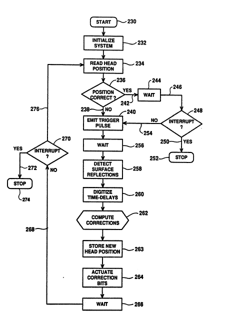
Now lod~ing to Fig. 7, a logic diag~m under which the computer
function 190 may petform is portrayed. The logic diagram commences
with a start node 230 whereupon, as represented at bloclc 232, the system
25 is inidalized. Following such inidalization, as represented at block 234,
the position of he~d 90 is ~d as it læt existed in mernory. With that data
recalled. then, as represented at decision block 236, a determination is
made as to wheth the posidon as it exists is coIroct. For an initial cycle,
the determination will be in the negative as represented at block 238, but
30 with the de~elopment of data as to correct orientation, the head 90 will
assume an optimal alignment. Thus, where such alignment is not
achieved, a trigger pulse or ranging input signal is unerated as
represented at blocl~ 240. The computational cycle involved is short
~re~ to t~ re~ltant ~ic~l D~ents of he~ 90 su~h th~t
su~ nt ~ rro~r ~8 cantinuaus. It is s~ oth ~ ~y us ~g
gre~ter th~n e~ght d~t~ b~ts, ~hidh ~18~ reduoe8 gu~ntiz~tion error.
Retuming to decision blocl~ 236, where a posidon oriontadon is
deterrnined to be co Tect, then u represented u line 242 and blocl~ 244, a
- - . ~ - . - . . - . . , , , .:
- - ~ . .
- . . ~, . . : . -
, . ~, . . .
.
, , , . _... :, , ' . ~ .
2078
24NS05209
dwell or "wait" interval occurs such that the remotely located opcradng
personnel may determine whether or not to stop the orientation program
after concluding surface tesdng. Accordingly, the program continues as
represented at line 246 and decision block 248 wherein a determination is
S made as to whether an interrupt from the operator has occurred. In thc
event that it has, then as represented at line 250 and node 252, the
program stops until another start-up condidon occurs. Where no interrupt
is received, the program continues as represented at line 254 and block
240, ~he latter, as before, calling for the emission of a trigger pulse or
10 ranging input signal. Following the emission of such signal for a given
channd associated with one of the ranging transducers, as set forth at
bloclc 256, the system waits undl an acousdc return occurs at thc
terminadon of a propagadon interval. This waidng period representod at
blocL 256 is se!ected as the maximum which the system will permit.
15 Then, as represented at blocL 258, surface reflections or acoustic return is
detected. This will have been treated by the signal treatment network af
Fig. S and will be recognized by the compuler with the output u line 174.
The program then condnues as represented u blocl~ 260 where the dme
delays represented by a propagadon interval are digitizod. In this regard,
20 while the output of counter 142 rnay be binary, some interface formafflng
may be called for prior to its use by the computer. Then, as sepresented at
bloclc 262, the program responds to the numenc range value and to a
predetermined optimal ientadon value to derive ientadon error signals
or co~rections. Such co~recdons then develop new binary head position
25 values which are stored as represented at bloclc 263. Additionally, upon
developing these arientadon ~.v. signals, as represented at black 264,
orientadon em~r signals or cv~recdon bits are developcd for selecdvely
actuadng head posidoning assemblies with drives such as stepper-devices
116 and 122. Following this actuadon, as represented u block 266, a
30 wait o~ dwell interval occurs, again giving thç opera or an opportunity to
interrupt the program. In this regard, the program is seen to loop as
represented at line 268 to the inql~iry at line 270. At this juncturç, the
program permits an inte~upt or response to an inte~upt on the part of
operadng personneL Accordingly, if such interrupt is present, then as
35 represented at line 272 and node 274, the program is stopped undl the
opaator detennin to commence it again at node 230. In the event that
no interrupt is present at this point in the program, then as represented at
-12-
: - . ,
,, ; .:
, ~ ,
' ' , .
2078~24
24NS05209
line 276, the head 90 positions are read again from memory as represented
at bloc~ 234.
Since certain changes may be made in the above sys~em,
apparatus, and method without departing from the scope of the invention
S herein involved, it is intended that all matter contained in the above
description or shown in thc accompanying dra vings shall be interpreted
as illustrative and not in a limiting sense.
. . ~ . . . - . ,
.. . - .; ,. .; , . . . , , . ,- - , .
: ... . . . . . . .
: ~ . ' ' ~ ~ ..... ... .
.. , - . . , . . , ;
.. ;