Note: Descriptions are shown in the official language in which they were submitted.
yd~ ~ma~~~~ ... ~~~a j~;9~ ~~I~~3
2~'~~~'~~
CHAISE LOUNGE WITH ADJUSTABLE CANOPY
TECHNICAL FIELD
This invention relates generally to a recreational and
vacational seating and lounging arrangement and more
particularly to a chaise lounge having an adjustable canopy
adapted to be moved in one of an infinite number of
positions between its upright and lowered positions.
BACKGROUND ART
Chaise lounges, having canopies mounted thereon, have
found widespread recreational and vacational use,
particularly at beaches and on the sun declcs and patios of
homes and hotels. However, the backrest for this type of
lounge, popular in Europe and elsewhere, is often-times
fixed in position. Thus, the user is unable to adjust the
backrest for his or her comfort. The lounge was later
modified to permit the backrest to pivot on the lounge.
However, the externally operated mechanical locking systems
utilized are difficult to manipulate and the substantial
weight of the backrest (e.g., 75 lbs. or 33.75 kg.) renders
the lounge impracticable for every day use.
U.S. Patent Nos. 2,243,984: 2,279,748 and 2,837,140
discloses various types of beach chairs wherein an
adjustable backrest or canopy is pivotally mounted on a
frame to adjust the inclination of the backrest from an
upright position to a lowered position. Chairs of this
type normally rely on legs or struts, positioned rearwardly
9J~Jf3 r)7 /1 ~'~iQS ~f'3'/d i_~',~919~D~~~~
2
20~~~'~0
of the pivot point whereat the backrest pivots on the
frame, for supporting the weight of the person sitting or
lying thereon.
DISChUSURE OF 1NVEP1T~CON
An object to this invention is to provide an improved
and easily adjusted chaise lounge useful for a wide variety
of recreational and vacational purposes. The lounge
includes a moveable canopy for optionally providing full
sun bathing or sun and wind protection, at the convenience
of the user.
The chaise lounge of this invention comprises a
stationary base frame having laterallypaced and
vertically disposed sides and a horizontally disposed top
adapted to retain a seating cushion thereon. A normally
upright canopy frame comprises laterally spaced and
vertically disposed sides, a top and a normally upright
back, all secured together to form a hood. The canopy
frame is pivoted rearwardly on the base frame to permit the
canopy frame to be moved through an infinite number of
positions between its normal upright position and its
lowered position, placing the back of the canopy frame in
at least general horizontal alignment with the 'top of the
base frame. A control system is adapted to release and
permit the canopy to be moved to a~selected position and to
hold and lock the canopy frame in such position, between
its upright and lowered positions. Such control system may
include one or more mechanical struts or a reversible
electric motor secured on the base frame and actuating
-Y3~:J i' ~ % I;i.:iv~ ...., i°Y. i %. ~,! ~'r~ 1 % di ~ t1S'3
3
means connected to the motor for moving the canopy frame to
its selected position in response to activation of the
motor.
BRIEF I?ESC1~IPTION OF Z'HE D1~WINGS
Other objects and advantages of this invention will
become apparent from the following description and
accompanying drawings whereint
Figure 1 is a partially sectioned frontal perspective
view of a chaise lounge with a canopy thereof shown in its
ZO fully lowered position and further showing various raised
positions of the canopy in phantom lines;
Figure 2 schematically illustrates a control system
including a combined holding and locking strut and its
attachment to an operator-controlled cable system far
selectively releasing the strut to permit pivotal
adjustment of the canopy;
Figure 3 is a partially sectioned view schematically
illustrating a combined cushioning and return spring strut
employed in the lounge of Figure 1 to cushion movement of
the canopy when it is moved to a lowered position and for
automatically moving the campy back to its upright
position in response to operator-release of the holding and
1 OCk3.ng Struts ;
Figure 4 illustrates an alternative control system,
including a motor-driven gear arrangement;
Figure 5 is a sectional view, generally taken in a
direction of arrows VI°VI in Figure 4;
Figure 6 partially illustrates a chaise lounge
2U7~~7~
utilizing the control system of Figure 4 therein: and
Figure 7 partially illustrates a repositioning of the
control system in the chaise lounge of Figure 6. ,
BEST MODE OF CARRYING OUT THE INVEfiITION
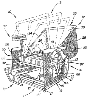
Referring to Figure 1, a chaise lounge 1o comprises a
base 11 having a canopy 12 pivotally mounted rearwardly
thereon by laterally spaced and aligned pivot pins 13 (one
shown) . The canopy is adapted to be selectively pivoted
from a normal upright position, forming a seating
arrangement, to its illustrated full line lowered position,
forming a bed-like or "sunning" arrangement. A hand or
operator-controlled cable system is adapted to release a
control system including a pair of laterally spaced
combined holding and locking struts 15, pivotally
interconnected between base 11 and canopy 12, to
selectively hold and lock the canopy in any one of an
infinite number of positions, as shown by phantom lines
12', between its normal upright and lowered positions.
The upper end of strut 15 is pivotally connected to
the frame of canopy 12 by a ball and socket connection 41
at a bracket 42. The strtat is pivotally connected to a ,
steel plate 33, formed integrally with the frame of base
11, by a ball and socket connection 44. A pair of
laterally spaced combined cushioning and return struts or
cylinders 16 of the control system are pivotally
interconnected between base 11 and canopy 12 at 68 , 67 to
cushion movement of the canopy when it is moved from its ,
upright position towards its lower position. Cylinders 16
~~li, Iii i~iJ~a i i.'ii Zi3J?iii33~:i1~
~~'~8~'~(~
further function to automatically move and return the
canopy to its upright position in response to release of
locking struts 15. Each corner of base 11 can be mounted
on a standard caster 17 to facilitate movement of the
5 lounge into various orientations for sun bathing, viewing
or similar recreational delights. A standard collapsible
and storable leg and foot rest 18 can be suitably mounted
on the frontal side of base 11 for convenience of the user.
The two struts 15 and 16 on each side of the lounge
can be combined into a single strut, pivotally
interconnected between the base and canopy similar to the
positioning of strut 15 in Figure 1 (or strut/actuator 15'
in Figure 6) , to provide a control system exhibiting the
combined holding, locking, cushioning and return functions.
For example, struts of this type are disclosed in U.S.
Patent No. 3,874,480 and can be purchased from P.L. Porter
Company of Woodland Hills, California, U.S.A. under its
Model No. MM65-2016 for a "Single Linear Locking Device
With Remote Control°' (Mechlok or Double-Lok).
Base 11 comprises laterally spaced and vertically
disposed opposite side panels 19 and 20 and a horizontally
disposed top or seat panel 21, adapted to retain a seating
cushion 22 and sub--cushion 32 thereon. The canopy
comprises laterally spaced and vertically disposed sides 23
and 24, a top 25 and a normally upright back 26, adapted to
have a back cushion 27 mounted thereon. Thus, when canopy
12 is moved to its fully lowered position illustrated in
Figure 1, back 26 of the canopy and top 21 of the base, as
?ry'~ j;%i=iJE35: i'Li%iJ~''J~'d%iD~FEIJ
_ 6
2~'~8~'~0
well as cushions 22 and 27, axe placed in at least general
horizontal alignment to form the bed-like or "sunning°'
arrangement for the user.
The sides, top and back of the canopy are preferably
covered with a woven, flexible material 28 to provide air
ventilation through the canopy for convenience of the user.
A porous liner 39 can be secured within campy 12 and a sun
shade 82 can be suitably mounted forwardly thereon. Woven
mufti-strip material 28, underlying back cushion 27, is
suspended in a hammock-like manner from side rails of a
frame of the canopy to provide the canopy with a high
degree of structural integrity and the desired amount of
flexibility.
Base 11 comprises a base frame composed of a plurality
of wooden or metallic frame members suitably secured
together to form a box-like rigid construction having an
open front side. Canopy 12 is also formed by a plurality
of structurally integrated wooden or metallic frame members
that form the rigid hood-like skeleton frame for contiguous
sides 23 and 24, top 25 and back 26 of the canopy.
Referring to figure 2, each strut 15 comprises a
partially illustrated tubular housing 45 suitably swaged at
46 onto a pair of identical and longitudinally spaced
collars or bushings 47. A rod 48 is reciprocally mounted
in the bushings and housing and has a pair of torsion coil '
springs 49 mounted thereon. One end of the rod is
pivotally mounted on canopy frame 34 at pivot connectian 41
whereas the opposite end of the rod remains free of
SfI'L lii i=iaut7. . 3'LIIL)S~~Jvi~i:3
. 2~7~~~~ .
7
attachment (Figure 1). A distal end 50 of each spring is
captured within a slot 51, defined on an inner end of a
respective bushing 47. A centrally disposed collar 52 is
rotatably mounted on rod 48 and has an actuation lever 53
extending radially outwardly therefrom.
A proximal end 54 of each spring is captured within a
slot 55 defined in collar 52. Thus, rotation of lever 53
to its phantom-line or release position 53' and against the
helix directions of the coil springs will expand their mean
diameters to release torsional friction on the rod to
permit it to reciprocate therein. When lever 53 is in its
normal full line "locked°' position, the coils of the
springs will contract automatically to frictionally grip
rod 48 and thus hold and lock the rod and canopy 12 in a
selected position.
A cable control system comprises a schematically
illustrated operator-controlled reciprocal handle (or slide
button) 56, adapted to selectively and simultaneously
reciprocate a pair of flexible cables 57 to release the
frictional gripping forces imposed on rods 48 by springs 49
of struts 15. Handle 56 is suitably mounted on a plate 58,
mounted on an inner side of sidewall 23 (or 24) within
canopy 12. The standard cables .are suitably guided by
brackets (not shown) secured on base frame 30 and canopy
frame 34 to ensure that a pulling of the cables will
function to unlock struts 15.
A distal end of each cable 57.extends through a slot
formed through a bracket 60 secured on housing 45 and
3'°Z.1~3,JJ~7~l4fii):J
YYil J1f 3-'i:u'3J u:a n-s
~UI~~I~J
8
further extends through a slot 61 formed in lever 53 and is
anchored thereon. Thus, pulling of cable 57 will engage an
enlarged terminal end 62 of the cable behind the lever to
pivot the lever for release of the strut. In particular,
when the lever is rotated by the cable to its phantom-line
position 53', it will rotate collar 52 generally clackwise
in Figure 2 to release the gripping force of spring 49 on
rod 48.
Housing 45, pivotally mounted at 44 on plate 33 will
pivot to compensate for relocation of the canopy to its
selected position. Further detailed description of strut
16 and its attendant actuating mechanisms can be found in
U.S. Patent No. 3,874,480. These types of struts can be
purchased from P.L. Porter Company of Woodland Hills,
California under its Model No. MM65-1016 (Mechlok).
Figure 3 schematically illustrates combined cushioning
and return strut 16 of Figure 1. Each strut is pivotally
interconnected, rearwardly of pivot pins 13, between each
side of canopy frame 34 and base frame 3o by ball and
socket pivot connections (or pins) 67 and 68, respectively
(Figure 1). The strut comprises a rod 69 reciprocally
mounted in a tubular housing 70. A standard compression
coil spring S (shown by phantom lines) could be mounted in
a spring and damping chamber 71, between a piston head 72
and the left end of the housing, to provide the basic
spring dampening and return functions of the strut.
However, it may prove preferable to utilize a standard gas
over oil cylinder or strut to more closely provide a
r. - = z-n- r~i'l.J:~'~~wi~=a
...i~.v 3ii n4._uv.
controlled and modulated spring force applied between the
rod and housing. This will insure that the canopy will
return to its upright position smoothly and slowly, when r
struts 15 are released from their locked conditions of
operation.
The well-known gas-oil cylinder nor strut is designed .
to permit a narmal maving force to lower the canopy, upon
release of locking struts 15, towards its selected lowered
position. The struts will exhibit sufficient force to move
the canopy back to its upright position in a smooth and
controlled manner when the locking struts are again
released in the above-described manner. Struts 16 may have
either their rod end or head end (Figure 1) pivotally
connected to canopy frame 34, depending on preference of
the designer. The standard strut may be of the "Type 16"
manufactured by SUSPA, Incorporated of Grand Rapids,
Michigan, U.S.A.
Struts of this type may include an annular chamber 70'
defined in housing 70 and one or more orifices 72' formed
through piston head 72 for communicating oil from chamber
71 to chamber 70'. A nitrogen gas is retained in the head
end of chamber 71 to function as a spring when the strut is
retracted and to expand when the strut is extended.
Orifice 72' (one or more of which can have a standard check
valve therein to return oil to chamber 70') will function
in a conventional manner to closely control the metering of
oil into chamber 71 when the strut is retracted.
~='17' 117
~ ~ ~7
~ 77 17 J'~9
~1.d1 1J~71%:~1:7~.7
.
7111 >111'1.10~
2~"~8 i'~~ ~ ~
to
Figures 4 and 5 illustrate an alternative control
system 15' to replace each strut 15 and to permit
elimination of struts 16 (Figure 1). The control system
comprises a threaded rod 48 adapted for axial movement in
a housing 45, under control of an operator switch 56',
adapted to be mounted in canopy 12. l~od 48' comprises
spiral teeth 64 adapted to be suitably engaged by meshing
teeth of a gear 49.
Gear 49! is rotatably mounted by axially spaced
annular bearings in housing 45' andv:has external teeth
meshed with external teeth of a gear 52'. Gear 52' is
secured to the distal end of a cable 57'. Thus, rotation
of the gear in Figure 5 will rotate gear 49' and move rod
48' axially in opposite directions, depending on the
direction of rotation of gear 52'.
One end of rod 48' has an eyelet adapted to be
pivotally mounted on pin 41 (or ball and socket) to pivot
the canopy of base 11 in the manner described above. A
pivot connection (pin or ball and socket) 44' pivotally
mounts housing 45' on a bracket adapted for securance to
steel plate 33 (Figure 1) to place the pivot axes of pins
41 and 44' in parallel relationship and positioned similar
to pins 41 and 44 (Figure 2). Operator-control switch 56
has a pair of buttons thereon to selectively activate a
reversible electrical motor 65 to, in turn, rotate flexible
cable 57' (similar to the speedometer cable of an
automobile) and gear 52' in its selected direction.
rr~ w :nn
...,. a.m v~7~ii::a>:i
v i. . ~I~rVV . . ..
~~'~~~'~0
11
A standard rechargeable battery pack 66 can be mounted
in base frame 30, along with motor 65, to provide the power
source for the motor. Control system 15' is preferred for
those chaise lounge applications wherein it proves
desirable to fully automate the lounge °'at the touch of a
button." In particular, the canopy can be moved, locked
and held at a selected position by simply operating control
switch 56' whereas the aforedescribed control system,
including struts 15, relies on manual power to move the
canopy down from its upright position.
Control system 15' can also be utilized in the 'manner
shown in Figures 6 and 7. As shown in Figure 6, a base
frame 30' comprises a plurality of metallic structural
members, such as aluminum ar steel tubing, suitably secured
together by welding or the like. A canopy frame 34°
comprises a reinforcement rail 43' on each lateral side
thereof and a steel plate member 36' is suitably secured on
the outside of each reinforcement rail. Fach plate member
36' is pivotally mounted on a horizontally disposed upper
frame member 31' of base frame 30' whereby the canopy frame
can be pivoted on the base frame in the manner described
above.
Threaded rod 48' and its actuating mechanism (Figures
4 and 5) are pivotally mounted at 44° on a bracket 83
suitably welded or otherwise secured to the inner side of
a vertically disposed base frame structural member 33°.
The distal end of the rod is pivotally mounted at a ball
and socket connection 41 to the lower end of a 7.ever 84.
~f i~~ it ma7~
~JZj 3fi%1=i.io~ ..
r
~vao~~~
12
The upper end of the lever is suitably secured within a
slot formed beneath the rearward end of reinforcement rail
43' by standard epoxy and/or a bolt 85. Although the upper
end of the lever is preferably secured to rail 43' at a
position forwardly of pivot pin Z3°, it could be secured to
the rail at a position rearwardly of the pivot pin.
Thus, extension or retraction of rod 48' will function
to move the lever in an arch to simultaneously pivot
structurally attached canopy frame 34 ° about the pivot axes
of laterally spaced pivot pins or bolts 13'. The above-
described drive mechanism for each rod 48' is controlled by
a respective rotary drive cable 57', further connected to
a standard split-drive power take-off 65'. The standard
power take-off may comprise, for example, a pinon gear
secured to the output shaft of motor 65 to mesh with a pair
of opposed face gears, such as of the Spiroid type of gears
manufactured by the Spiroid Divisian of Illinois Tool Works
of Chicago, Tllinois, U.S.A.
Thus, selective actuation of reversible motor 65,
under control of button switch 56' (Figure 4), will
energize the motor via battery 66 to simultaneously extend
or retract rods 48' the desired amount. When the button is
released after the canopy has been pivoted to its selected
position on the base, the actuating means (gears, cable,
etc.) for the rod will simultaneously and automatically
hold and lock the canopy in such position relative to the
base. Sufficient clearances and relative movement is
provided by ball and socket connections 41 and 44' to
'i-.'~ '~~:~:--'ate;;: 1 ??i ~i3~ii i3iil~~
13 20'~~~'~0
facilitate pivoting of the canopy between its upright and
fully lowered positions.
Each rod 48' is suitably designed to extend and
retract the proper amount to accomplish the same. Piaximum
extension of the rod in one direction in Figure 6, to
place the canopy in its fully upright position, is
controlled by a stop collar 50, whereas maximum extension
of the rod in the opposite direction to place the canopy in
its fully lowered position (Figure 1) is controlled by a
stop collar 50'. The stop collars can be swaged or
otherwise suitably secured to the rod once the proper
extents of travel of the rod have been determined.
Although Figure 6 shows each generally horizontally
disposed rod 48' positioned adjacent to the upper end of
the vertical base frame member 33', it should be understood
that this positioning and location could be changed. For
example, each mounting bracket 83 could be secured to the
lower end of a respective member 33' to position each rod
48' and its attendant drive mechanism adjacent to ground
level. Lever 84 would be suitably lengthened to
accommodate such positioning and to substantially lengthen
its effective moment arm, i.e., increase the "mechanical
advantage" of the control system whereby relatively less
power would be required to pivot the canopy.
Figure 7 illustrates a general vertical disposition of
each rod 48' in contrast to the general horizontal
disposition of the rads, shown in Figure s. A bracket 83'
is welded or otherwise suitably secured on vertically
am:~xiivav-~
IYi.J ll% I=iJs~a :~.~ u: ~~:an ~~ a ~ n~
14
disposed base frames member 33° to mount the actuating
mechanism (Figure 4) for the rod thereon. The vertical
disposition of the bracket is such so as to permit the rod
to extend and retract a sufficient amount to enable the
canopy to be pivoted between its upright and fully lowered
position on the base as dictated by stop collars 50,50'.
Instead of using a common motor 65 as shown in Figures
6 and 7, a separate motor could be provided for directly
driving gear 52' (Figure 5) for each actuating mechanism
for the rod, i.e., cables 57' and power take-offs 65° could
be eliminated. Each motor could be suitably mounted on a
respective member 33' (Figures 6 and 7). Although it is
preferable to have an actuating mechanism connected to each
side of the lounge, it should be understood that in certain
applications it may prove desirable to only utilize a
single combined moving, holding and locking system an one
side thereof. As suggested above, a single mechanical
strut, such as the type disclosed in U.S. Patent Na.
3,874,480, could replace control system or actuator 15' in
Figures 6 and 7 to provide combined holding, locking,
cushioning and return functions of the kind described
above.