Note: Descriptions are shown in the official language in which they were submitted.
1
2078938
GAMING MACHINE INFORMATION, COMMUNICATION AND DISPLAY SYSTEM
Technical Field
The invention relates to the field of amusement and
gaming machines, and in particular to a method and system for
permitting such gaming machines to communicate with a central
control system, allowing the player or operator to communicate With
the system, and permitting cashless operation of such gaming
machines.
Background of the Invention
Gambling casinos and other establishments often have
large numbers of individual gaming machines, such as slot machines
and video gaming machines. For some time it has been desirable to
automate accounting, security and other functions related to such
machines for efficiency, reliability and economy. Data transfer
systems for providing accounting and security information to casino
operators have been described in U.S. Patents 4,072,930,
issued February 7, 1978; 4,283,709, issued August 11, 1981;
and 4,636,951, issued January 13, 1987. The systems known
in the art, however, have been principally directed toward
reporting data from the gaming machines to the central
computer, and have not provided for transmission of data
from the central computer to the individual machines.
Further, such systems have not provided any means by which a player
or employee can communicate with the system. Another disadvantage
of these systems is that their functions have been very limited,
primarily for reporting accounting data to the central computer.
In the past it has not been possible for a player to
interrupt his play, leave the machine briefly, and then return and
resume play. It is desirable to provide a reservation feature so
that a player can temporarily reserve a machine.
It is also desirable to permit cashless gaming so that
the player does not need to carry large sums of cash or obtain
change in different denominations for the different machines he
wishes to play. A gaming system using credit cards wherein
approval and credit is provided by a remote financial institution
2078936 ~'
- 2 -
is disclosed in U.S. Patent 5,038,022, issued August 6,
1991. However, that system does not permit winnings to be
credited directly to a player's card or account, and
contemplates the involvement of a third-party bank or other
financial institution.
Summary of the Invention
It is therefor an object of the invention to
provide a system for automating maintenance, accounting,
security, player tracking, event recording and other
functions for a plurality of gaming machines.
It is a further object of the invention to provide
a system including display and data entry means which permit
the player or employee to interact with the system.
It is a further object of the invention to provide
a cashless gaming system in which the player may play a
plurality of gaming machines using a single card in lieu of
cash, and his winnings may be directly credited to his card.
It is a further object of the invention to provide
a means for a player to temporarily reserve a gaming
machine.
It is another object of the invention to provide a
signal to casino personnel to identify special players.
It is yet another object of the invention to
provide for the downloading of data from the central data
processor to the individual gaming machines.
In one aspect, the present invention provides an
information and communication system for use with a player
controlled gaming machine comprising: a central data
processor; control means located within said gaming machine
for communicating between said central data processor and
the gaming machine; and an interface unit, separate and
additional to the gaming machine, including a keypad, a card
reader and a display secured to the gaming machine and
operatively connected to said control means wherein said
2x78936
- 2a -
keypad transmits player generated information to said
central data processor.
In another aspect, the present invention provides
a gaming machine reservation system comprising: a gaming
machine housing; game control means located within said
housing for controlling the gaming machine; reservation
means operatively connected to said game control means for
permitting a player to reserve the gaming machine.
Brief Description of the Drawings
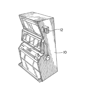
FIG. 1 is a perspective view of a gaming machine;
FIG. 2 is a perspective view of the display,
multiple card reader and keyboard unit for use on each
gaming machine in the system;
FIG. 3 is a functional block diagram of the system
of the invention.
Detailed Description of the Invention
SYSTEM HARDWARE AND OPERATION
The system of the invention provides multiple
features including game accounting, security, maintenance,
player tracking and employee/player interaction from the
game to the computer. The gaming machine to shown in FIG. 1
includes the present invention
i
2078936
- 3 -
which provides these functions and features. The system of the
invention is designed to be flexible and compatible with existing
gaming machines and systems. FIG. 2 shows the display, multiple
card reader and keypad (DMK) unit 12 which is mounted on the
cabinet of the gaming machine 10 of FIG. 1. The DMK 12 is the only
portion of the system accessible to the player.
As shown in FIG. 3, the primary hardware elements of this
system are a control unit called the MASTERCOM 14; a DMK unit 12;
and a main computer 16. A MASTERCOM 14 is required for each gaming
machine 10 in the system, and a DMK unit 12 is needed for each
gaming machine 10 for which the display, card reader and
employee/player communications features are desired.
The main (or host) computer 16 may be a personal
computer, for example, an IBM RT class or compatible, or a
minicomputer such as a DEC 1184 or IBM RISC 6000, depending on the
size of the installation and the number of gaming machines. The
main computer 16 may also consist of two or more such computers
linked together. The main computer 16 is located remotely in the
casino, preferably in a secured area, and communicates with the
MASTERCOM units 14 via a computer interface unit (CIU) 18.
The term MASTERCOM is derived from its functions:
Maintenance, Accounting, Security, player Tracking, Event Recorder,
Communicator. In the preferred embodiment, the- MASTERCOM 14 is
contained on a single circuit board 20 which has a microprocessor
or microcontroller 22 such as the Motorola MC68HC705C8
microcontroller. The board 20 also contains memory including
random access memory (RAM) and some form of read-only memory (ROM) ,
such as EEPROM. Typically, a 128-byte EEPROM may be used for
storing game personality data, and a 32-byte EEPROM may be used for
storing the accounting meters. The MASTERCOM 14 is connected to
the DMK 12 via a serial port 24. The MASTERCOM board 20 is fairly
compact (on the order of 4.5 x 6.5 inches) and may be conveniently
located inside the gaming machine cabinet 10. The MASTERCOM 14 is
powered by an external power supply 26. A 10-year lithium battery
28 is provided to back-up the RAM.
2078936
- 4 -
The DMK 12 is the interface and communications device
between a player or employee and the MASTERCOM 14. The DMK unit
12 may be mounted directly in the gaming machine cabinet 10 or
attached to an existing cabinet as shown in FIG. 1. As shown in
FIG. 2, the DMK 12 houses a 12-character dot-matrix LED display 30,
a 12-key user interface keypad 32, and a combined magnetic/smart
card reader 34. In the preferred embodiment shown in FIG. 2, it
also includes a three-color LED 36 for special customer
identification, and a small sound module 38 for alerting the player
to an important message. Like the MASTERCOM 14, the DMK 12 is
controlled by a microprocessor 40, using, for example, a Motorola
MC68HC705C8S. The DMK 12 receives power from the MASTERCOM 14.
The microprocessor 40 and related circuitry are mounted on a small
circuit board 44. The keypad 32 and display 30 may be mounted on
the reverse side of the circuit board 44 to save space.
The personality stored in EEPROM is a list of variable
parameters containing addresses, coin denomination, limits and
characteristics that vary from one gaming machine and/or casino to
another. The MASTERCOM 14 and its microprocessor 22 will not
function properly unless a valid personality has been installed.
On power up, reset and at periodic intervals, the MASTERCOM 14 will
test the personality in the EEPROM and determine if it is valid by
looking at the check sum. If the personality is invalid (bad check
sum) or none exists, the MASTERCOM will display a flashing "EMP
CARD" on the DMK 12 and will halt communications with the main
computer 16. Only after the problem has been corrected and at
least the MASTERCOM address has been entered will the MASTERCOM 14
resume communications with the main computer 16. The address is
a four digit number which is converted to a two digit hexadecimal
address for the MASTERCOM. This is the address used by the main
computer 16 to communicate with the particular MASTERCOM 14 via the
CIU 18.
Once an employee card has been inserted into the card
reader 34 in response to the "EMP CARD" prompt, the DMK 12 will
display a prompt with "ADDR xx" so the employee can immediately
20 789 3 6
- 5 -
enter the personality, beginning with the address, or can command
the main computer 16 to download the personality. To manually
enter the personality, the employee begins by entering four digits
which are the ASCII equivalent of the two digit hexadecimal address
as shown in the following table:
HEX TO ASCII CODES
HER ASCII HEX ASCII
0 30 8 38
1 31 9 39
2 32 A 41
3 33 B 42
4 34 C 43
5 35 D 44
36 E 45
7 37 F 46
After the address has been entered, the display 30 will prompt the
employee to enter other variables seriatim, for example, COIN (coin
type), MXIN (maximum coin in), etc.
The following elements of the MASTERCOM personality, or
operating parameters, may be casino-defined and changed as needed
via the MASTERCOM keypad 32 as explained in more detail below:
1) Machine system address
2) Machine Paid Jackpot Notification-the minimum size
of a machine paid jackpot (in coins) which will produce an
exception code (63), which will produce a special change booth
message notifying casino personnel of the jackpot so they can
refill the machine's coin hopper.
3) Maximum coin in-used by MASTERCOM to verify the
jackpot amounts
4) Maximum jackpot number-used in games which
communicate serially with the MASTERCOM to define which jackpot
codes will be received from the game.
5) Progressive Jackpot Table-a list of which
progressive jackpot Ids may be hit on this game.
6) Maximum number of progressive jack ots
p (available
on this game)
2p X89 36
- 6 -
7) Minimum number of coins per handle pull required
for "Hot Handle"-many games permit multiple coins to be played in
a single game, i.e, on one handle pull in a slot machine. If a
player repeatedly plays multiple coins, the "hot handle"
designation will apply.
8) Number of Handle Pulls for "Hot Player"-number of
hot handles needed to generate a hot player message
9) Period of time for Hot Player-amount of time a
player has to accumulate the required number of hot handle pulls
10) Reset Time for Hot Player-the amount of time
between handle pulls (no play activity) before the Period of T~.me
for Hot Player is reset.
11) Service Button Delay-period of time before a
service message is sent; message is sent only if employee has not
serviced player and canceled message:
12) Disable Service Button-length of time between
enabling service request messages.
13) Time for Employee Card-length of time before
producing an abandoned card message for an employee card.
14) Time for Player Card-length of time before
producing an abandoned card message for a player card.
15) Starting Amount of Bonus Point Countdown-the reset
value for the countdown display; the countdown resets to this value
when a different player card is inserted into the card reader or
a countdown cycle has occurred.
16) Bonus Point Amount Earned for Each Countdown Cycle-
the award amount may be of any multiple or percentage desired.
17) Number of Coins per Bonus Point-the number of coins
in required to earn x number of bonus points.
18) Number of Coins per Countdown Amount-the number of
coins in required to reduce the countdown amount by x amount.
The personality also contains information for other
casino-defined functions, such as the service requests discussed
below and the definition of the colors on the three-color LED 36
for indicating special players.
2 0 X89 3 6
The DMK 12 receives three types of input data: card data
read from a card inserted by either a player or employee; keypad
entry data from either a player or employee; and display commands
from the MASTERCOM 14. The DMK 12 transmits three kinds of data
directly to the MASTERCOM 14: card data read from the card reader
34; keypad entry data from the keypad 32; and display command data
to inform the MASTERCOM 14 that the DMK 12 is processing the
display command that was sent to it. Data is transmitted to and
from the MASTERCOM using the Serial Peripheral Interface (SPI) 42.
The DMK's SPI 42 is set up as a slave device. The DMK 12 can
receive data at a maximum rate of 2.1 Mhz, which has been found to
be sufficient for the intended purposes.
The display 30 consists of 12 alphanumeric characters
with associated firmware for control. The firmware controls and
provides timing and sequencing for the SPI 42, card reader 34,
keypad 32 entry, and characters or words displayed. The display
30 receives the various display commands via the SPI 42 from the
MASTERCOM 14.
The message types include the following:
(1) ROM scrolled message - A message stored in ROM is continuously
scrolled across the display 30 when the MASTERCOM 14 is in the
"attract" mode, i.e., when the game is not being played or
serviced. (2) Down-loaded RAM messages - Special messages such as
promotional messages or current sports scores may be downloaded
from the system and displayed; (3) Jackpot amount; (4) Hand pay
jackpot amount; (5) LED 36 or sound unit 38 control; (6) Bonus
information - A player may earn bonus or frequent player points by
spending a predetermined amount; (7) Bad communications - messages
indicating problems with communicating with the system; and (8) 8-
or 12- digit fixed word messages.
The DMK 12 receives several types of display messages
from the MASTERCOM 14. The message types are single byte commands,
multi-byte commands, and down-loaded messages. The DO-type message
is actually a two-byte message: DO plus a display command byte,
which informs the DMK 12 what to display. Some types of display
2o~s93s
_$_
commands are ROM scroll, STANDBY, TRANSMIT, INVALID, etc.,, each
represented by a hexadecimal code.
The D1-type message is a multi-byte message as shown in
the following table:
Byte No. Message Data
1 Message type (D1 HEX)
2 Message Length (HEX, excluding check sum)
3 Display command (HEX)
4-n Message (ASCII)
n+1 Check sum
The message length is the number of bytes in the message
plus one for the display command. The display command byte informs
the DMK 12 the format in which to display the message. The display
commands include employee card sequence, bonus points, jackpot with
amount, hand paid jackpot with amount, and employee keypad entry
prompts. The check sum is the two's complement sum of all the
bytes of the message.
There are three basic types of downloaded messages:
promotional, sports and player reply. Promotional messages include
notices of special events in the casino, special rates and the
like. Sports messages give scores of current sporting events for
the player's information and entertainment. Player reply messages
request the player to enter some requested information.
In addition to the messages sent by the MASTERCOM 14,
a poll is sent to the DMK 12 every 100 msec. A poll is a single
byte command (80 HEX). After the poll is sent, the DMK 12 should
reply with one of three types of messages: status, keypad or card
data. The status message is a three-byte message consisting of the
following bytes: ASCII S, current display status and current card
status. If the display status is not the same as the MASTERCOM's,
then the MASTERCOM 14 will retransmit the current display message.
After ten tries, the MASTERCOM 14 will reset the DMK 12.
The keypad message is a single-byte message containing
the key code of the key pressed. The card data message is a 9-byte
message as shown in the following table:
2078936
_ g _
Byte No. Message Data
1 Message type (C1-C8 HEX)
2 Message length (6 HEX, excludes check sum)
3-8 Card data (6 HEX bytes)
9 Check sum
The message type sent to the MASTERCOM 14 indicates card status as
set forth in the following table:
Code (HEX) Definition
C1 Good card read with 6 data bytes
C2 Card completely out
C3 Bad card read
C4 No data on card coming out
C5 No data on card coming in
C6 Card is coming out
C7 Rear sensor seen without front sensor
C8 Timeout on card going in or coming out
The message length is always 6 bytes. The card data contains
player or employee information that is stored on the card. The
check sum is the two's complement sum of all the bytes in the
message.
In the preferred embodiment, the card reader 34 is a
combined magnetic and smart (memory) card reader, for example, a
combination of the Tatsuno* smart card reader 46 and a Neuron*
magnetic card reader 48. This permits the system to accept both
types of cards. Although the magnetic card alone is sufficient for
many system functions, the smart card by virtue of its on-board
memory permits additional functions, and is especially useful in
cashless gaming as described in more detail below.
The magnetic card reader 48 accepts bit stream data from
an inserted magnetic card. Four inputs are used to detect the data
and card position: front card sensor, rear card sensor, data
strobe and data. The data bits are taken in bit by bit on each
data strobe input and stored in contiguous memory. There are four
records encoded on track 1 of the magnetic stripe of either 15 or
16 character lengths. Each record is preceded by two bytes of
zeroes (0) followed by one or two START sentinels ($45), 12 DATA
characters, one STOP sentinel ($1F) and a LRC. The LRC is the
(* Trade Mark)
..~v.,...... ~.:.f. :i.;.
y
2078936
- 10 -
exclusive OR'd result of all characters from the START sentinel
though the STOP sentinel. Each data byte is 7 bits long with the
seventh bit being an odd parity bit. This seven bit data is then
converted to six (6) hexadecimal data bytes for use by the system
(see table below).
The card data characters are set forth in the following
table:
Byte No. Card Data Character
1 START sentinel ($45)
2 START sentinel
3 Casino ID number - MSD
4 Casino ID number - LSD
5 Employee or player code
6-10 Customer number
11-14 Customer/employee number
15 STOP sentinel ($1F)
16 LRC
The raw 7-bit card data is converted to hexadecimal as follows:
Raw 7 Bit Card Data Converted Hex Data
100 0101 45 (START)
001 0000 0
101 0001 1
101 0010
001 0011 3
101 0100 4
001 0101 5
001 0110 g
101 0111
101 1000 g '
001 1001 g
110 0001 A
110 0010 B
010 0011 C
110 0100 D
~
010 0101 E
010 0110 F
001 1111 1F (STOP)
If the front card sensor only is seen, indicating
card going in or stopped, a timer is started. If no rear sensor
is seen after 4 seconds, a code is sent to the MASTERCOM 14 and the
timer is reset. The timer is also cleared on card out.
- _ 207893fi
- 11 -
If the rear sensor is seen, indicating card in and
seated, the front sensor timer is cleared. If the front sensor has
not been seen, a bad front sensor code ($C7) is sent to the
MASTERCOM 14. Otherwise, the raw card bit stream data is analyzed.
If there is good data on one of the four records, a $C1 code is
sent to the MASTERCOM 14. If there is a bad card read, a $C3 code
is sent. Raw read data is cleared so the card can be read on the
way out. When the rear sensor is no longer seen, indicating that
the card is coming out, a $C5 code is sent to the MASTERCOM 14.
If there is no front or rear sensor, the card is out.
If there is no raw card data, a $C4 code is sent; if there is card
data, a $C2 code is sent.
After the player inserts his card containing good data,
a welcome greeting including the player's name is displayed on the
DMK 12. If applicable, his current accumulated bonus points and
amounts needed to play to earn his next bonus paid will then be
displayed.
The keypad 32 consists of 12 keys in a 3 by 4 matrix,
including the digits 0 through 9, "CLR" (clear) and "ENT" (enter).
The keypad 32 is polled every 10 msec. Keypad entries are verified
for valid keypad entry by the DMK 12 and then passed directly to
the MASTERCOM 14. The keypad codes sent to the MASTERCOM 14 are
as follows:
Code Key or key combination
11 0
1 1
2 2
3 3
4 4
5 5
6 6
8 8
9 9
10 CLR (Clear)
12 ENT (Enter)
13 CLR + ENT (backspace)
. 207893fi
- 12 -
The player may use the keypad 32 to enter his PIN and
credit requests for cashless gaming as described below. The player
may also use the keypad 32 to request cocktail service, change, or
machine service, or to reserve the machine 10. The codes may vary,
but may be, for example, 1 + ENT for cocktail service, 2 + ENT for
change, 3 + ENT for service, and 4 + ENT to reserve the machine 10.
Entering the code for cocktail service, change or machine service
will send a signal to the system to notify the appropriate employee
to respond. The reservation feature is an innovation which allows
l0 a player to interrupt his play and return to the machine later,
resuming play where he left off. Upon entry of the reservation
code, a timer is started and the machine enters the reserved mode
in which no other player may use the game. The player then removes
his card and may leave the machine. When the player who reserved
the game reinserts his card, play may resume. If the player does
not return in a predetermined length of time, e.g. , 10 minutes, the
reservation feature times out and the game returns to the attract
mode. The reservation mode may also be canceled by insertion of
an employee card into the card reader 34. An employee may also
invoke the reservation feature without a time limit.
An employee may use the keypad 32 for a variety of
functions not available to players. A valid employee card inserted
into the card reader 34 will enable employee keypad entries. The
DMK 12 will first display the following series of status messages:
Display Definition
ADDR XX MASTERCOM Address
EXCD XX Last exception code sent to MASTERCOM
BET XXXX Last game - amount bet
PAY XXXX Last game - amount paid
PER# MST1001 Program (personality) identification
Upon completion of the sequence, the DMK will prompt
with a display of "MODE 00." The sequence may be aborted at any
time before reaching MODE 00 by depressing any key on the keypad
32. Removal of the employee~card from the card reader 34 will
terminate the operational mode routine and return the DMK 12 to
normal system operations. The MODE 00 display is the normal entry
2 0789 3 6
- 13 -
point for execution of employee operations. The employee enters
the desired command and then presses ENT to start the operation.
The employee commands are READ PERSONALITY MODE (O1), ALTER
PERSONALITY MODE (02), TEST MODE (03) and "911" EMERGENCY/MESSAGE
TRANSMISSION MODE (91).
The READ PERSONALITY MODE allows the employee to review
the personality of the MASTERCOM 14 for a given game. As
previously discussed, the personality is a list of variable
parameters containing addresses, coin type, limits and
l0 characteristics that vary from one game and/or casino to another.
The MASTERCOM 14 will not function properly unless a valid
personality has been installed. An employee may select READ
PERSONALITY MODE directly without authorization from the main
computer 16. This mode only allows the employee to review the data
without making any changes . By repeatedly pushing the ENT key, the
employee can step through each line of personality data. If no
personality is installed, or if the personality is invalid, an
appropriate message will be displayed.
To enter the ALTER PERSONALITY MODE, the employee must
obtain authorization from the main computer 16. This security
device prevents unauthorized tampering with the game personality.
Once cleared by the main computer 16, the employee may then step
through the lines of data using the ENT key, and may enter changes
using the keypad 32 . The employee may also cause a .new personality
to be down loaded from the main computer 16.
The TEST MODE causes a self test routine to execute and
to report on the display any system problems or errors. In the
TEST MODE, all signals received by the MASTERCOM 14 are displayed
to insure proper operation of all inputs. The test routine looks
at certain flags in the MASTERCOM 14 and displays the trigger
status of the discrete inputs as the employee triggers the discrete
devices. The exact tests will vary depending on the type of
machine personality. The test mode may be selected without main
computer 16 authorization.
-_ 20 789 3 6
- 14 -
The EMERGENCY 911 MODE allows an employee to quickly
send a request for emergency assistance to casino security in case
of a medical or other emergency. The exact location of the game
on the casino floor (based on its address) will instantly be
provided to security personnel, facilitating a quick response. To
enter this mode, the employee will insert his card and at the
prompt MODE 00 will enter "91" + ENT. This will transmit an
exception code (24) to the main computer 16, requesting that help
be sent to the location of the MASTERCOM/DMK. The display 30 will
then show "TRANSMIT" to let the employee know the exception code
24 has been transmitted. After the MASTERCOM 14 receives
acknowledgement of the transmitted code from the main computer 16,
the display 30 will show the message "HELP IS...COMING." This
display will remain until the employee card is removed.
Other modes which may be provided include an ENTRY mode,
in.which a two-digit code is displayed to indicate the reason of
entry into the game 10, i.e., a door open condition. It is
important for a casino operator to keep track of reasons for entry
into the game for security and regulatory reasons. In the WORK
ORDER mode, an automatic work order is sent to the casino's repair
shop when a game is placed out of service.
As previously mentioned, in the preferred embodiment a
multi-color LED 36 is provided on the DMK 12. This LED 36 is
lighted to indicate to casino personnel that a special player,
e.g., a "high roller" or "VIP" is playing the game, and may be
worthy of special treatment. The criteria for each color may be
defined by the casino, and may be based on data stored on the
player's card as well as the amount being played.
As shown in FIG. 3, each MASTERCOM 14 communicates with
the main computer 16 via the CIU 18 using balanced line serial
communications. Up to approximately 125 or more MASTERCOM units
may be hung on a single line, and in a large casino the line may
be many hundreds of feet long with.
The MASTERCOM 14 interfaces with the gaming machine 10
by direct wire and/or RS/232 communications 50. Adapters in the
2078936
- 15 -
form of piggyback circuit boards may be used to interface the
MASTERCOM 14 with various types of gaming machines from different
manufacturers. The MASTERCOM provides multiple door interfaces,52
for the game, drop, electronic security and auxiliary doors on the
gaming machine 10. The MASTERCOM 14 also provides a port 54 for
a progressive gaming system link 56.
An optional handheld keyboard and display unit 58 is
provided for the convenience of employees. This may be especially
useful if a DMK unit is not available on a particular gaming
machine or is out of service.
A lockout connector 59 is also provided on the MASTERCOM
14. By connecting the MASTERCOM 14 to the coin mechanism of the
gaming machine 10, it is possible to lockout, or reject, all coins
inserted into the machine.
The MASTERCOM 14 also provides additional high-speed
serial ports 60, 62 and 64 for options such as a bill changer
interface, a ticket dispenser interface, or cashless gaming
control. The bill changer allows the machine to accept currency
in addition to coins. The ticket dispenser may be used for various
purposes, such as to print a jackpot slip for a hand pay jackpot
which can be taken to the cashier at the player's convenience, or
to dispense bonus tickets for certain levels of play which may be
redeemed in the casino for prizes.
CASHLESS GAMING
An important benefit of the invention is the capability
to easily provide completely cashless gaming in several different
possible formats. Among the advantages of cashless gaming are that
the player need not carry large amounts of cash or obtain change
in the correct denominations for each type of machine he wishes to
play.
In one embodiment including the cashless gaming feature,
a magnetic (credit) card is used. The operating procedure for this
"cashless" or "credit card" gaming i~ as follows. The player
inserts his magnetic card into the magnetic 48 or combined
magnetic/smart 34 card reader in the DMK 12. Upon detecting the
w 2o~s93s
- 16 -
insertion of the card, the DMK 12 will prompt the player by means
of the display 30 to enter his personal identification number (PIN)
via the keypad 32. After the PIN is entered, the DMK display 30
will ask the player to enter the credit amount desired to be used
on the game. The player will enter this amount via the keypad 32.
The PIN and credit amount are transmitted to the system for
verification (either at a financial institution or at the casino,
depending upon the issuer of the magnetic card). If a correct PIN
and valid amount have been entered, the main computer 16 will
return an authorization amount and a code to the MASTERCOM 14, and
the verified amount will be shown on the display. As play
proceeds, the credit balance will be updated and displayed in
dollars and cents on the display 30.
For convenience, in the preferred embodiment the minimum
and maximum amount of credit permitted on each request will be a
function of the game denomination. For example, a one roll coin
equivalent may be used as the minimum, and five rolls may be used
as a maximum. For a quarter (25 cent) machine, one roll of
quarters equals $10.00, so the minimum credit request would be
$10.00 and the maximum would be $50.00, with amounts in between in
$10.00 increments.
Once the credit amount has been verified, the player can
proceed with game play. On gaming machines already equipped with
credit play capabilities, the player will bet using switches on'the
gaming machine 10 itself. On older noncredit model machines, a
separate BET button may be provided on the DMK unit 12. As play
proceeds, the MASTERCOM logic keeps track of credits and debits,
and the current balance is shown on the display. When the player
is finished playing, he can check his balance on the display 30 and
then remove his card. Upon removal of the card, the MASTERCOM 14
will transmit the balance amount to the main computer 16, which in
turn will return a message received code. The display 30 will then
indicate "VERIFIED" and show the balance recorded by the system,
and thereafter will return to the promotional display mode.
_ 2078936
-1,-
In another embodiment including cashless gaming, a
"smart" or memory card is used. With this type of card, there is
limited system involvement during cashless play. The player
purchases from the casino cashier or other source a smart card with
a dollar amount credited to the card. This becomes in effect the
player's "bank." The player inserts the card into the smart 46 or
combined smart/magnetic card 34 reader, and his ID number and the
bank balance are sent to the MASTERCOM 14. No credit authorization
is required, because the player is carrying his "bank" with him on
his card. The player then plays the game in the normal manner.
Each bet is subtracted (debited) from his card, and any wins are
added (credited) to his card. If the card balance is reduced to
zero, the player must remove the card and return to the cashier to
purchase more credits for the card.
The smart card is mechanically locked into place in the
reader 34 upon insertion, and remains locked until the player
request removal by pushing a button. At this time, the card
balance is updated, and the new balance sent to the MASTERCOM 14.
A smart card may also be used in another embodiment with
full system involvement. In this embodiment, the smart card is
used in the same manner as a magnetic card. However, the smart
card has the added security of carrying the bank balance on the
card, which can be cross-checked by the system upon insertion of
the card into the reader. The player can request the system to
increase his smart card credit amount by debiting his central bank
account. This transaction will be subject to verification and
approval through the system. Credit amounts can be stored on the
smart card and carried from machine to machine. This is a distinct
difference from the magnetic card where the credit amounts are
stored solely on the system. With the magnetic card, the player
must request a transfer of credits from the system each time he
inserts his magnetic card.
From the above discussion it is apparent that the
invention provides a gaming machine system with multiple features,
not only providing the casino operator with extensive information
20 ~s9 3 s
-18-
for casino management, but also allowing the player and employee
to interact with the system. Although the system has been
described in terms of its use with gaming machines which return
money to the player, many aspects of the invention would also apply
to coin-operated amusement type games.
A specific embodiment of the invention for use with
gaming machines in a casino has been described for purposes of
illustrating the manner in which the system may be made and used.
It should be understood that implementation of other variations and
modifications of the invention in its various aspects will be
apparent to those skilled in the art, and that the invention is not
limited to the specific embodiment described. It is therefore
contemplated to cover by the present invention any and all
modifications, variations and equivalents that fall within the true
scope and spirit of the basic underlying principles disclosed and
claimed herein.