Note: Descriptions are shown in the official language in which they were submitted.
CA 02079144 2001-07-31
1
The present invention relates to a switching
assembly for telecommunication and data technology optical
fibres, and in particular to an optical fibre partitioning and
terminal rack, comprising a frame supported on the rack, with
a jumper field for the optical fibres and with at least one
magazine provided with slide-in openings for splice cassettes.
Switching assemblies of the aforementioned spacies
allow the separation, for measurement purposes, of a plug
connection between incoming and outgoing optical fibres. The
incoming and outgoing optical fibres have to be easily
accessible and be able to be cross-connected, i.e. connected
in any desired manner. The switching assemblies serva_, in
particular, for the local fibre-optic network (overlay
network) of respective telephone companies.
A switching assembly of the aforementioned species
is known in the art from "telecom report", vol. 10, March
1987, pages 27 to 32. In such a switching assembly adapted
as a optical fibre terminal rack, 60 plug connections are
provided in a central patch field mounted on a frame of the
terminal rack. The optical fibre plug connectors are pre-
assembled, in a factory, as so-called pigtails ( comprising
a plug connector with a length of optical fibre), which have
to be welded at the installation site to the optical fibres.
For this purpose, a magazine provided with slide-in openings
for splice cassettes is provided in the lower section of the
frame in the terminal rack. The magazine is adapted to be
flapped out from the frame (which is supported at the rack)
to facilitate removal of the splice cassettes.
Further, as a switching assembly, an optical fibre
partitioning rack is known in the art, which comprises three
opposed splice fields, i.e. magazines provided with slide-in
openings for splice cassettes. The upper magazine is used for
the optical fibres of the interoffice fibre-optic cables,
while the central magazine is used for the optical fibres of
the internal fibre-optic cables of the exchange office, and
CA 02079144 2001-07-31
2
the lower magazine is used for the optical fibres of: the
subscribers' fibre-optic cables. The connections between the
various optical fibres are established by switching wires.
In both of the above-mentioned embodiments., 10
splice cassettes of each splice field are combined in a
respective magazine which is located on a flap-out arm, from
which a cassette can be taken out and "wired" at the work
table. The switching assemblies for optical fibre
telecommunication and data cables described above haves the
disadvantage that there is relatively poor accessibility to
the incoming and outgoing optical fibres, resulting in a high
risk of breakage, particularly when splicing.
It is therefore an object of the invention to
improve the switching assembly for optical fibre
telecommunication and data cables such that handling is
substantially easier, so that there is a low risk that only
individual optical fibres are damaged, and that in particular
the fibre bundle of the main optical fibre cable will not be
broken.
According to an aspect of the present invention,
there is provided a switching assembly including a cable
partitioning and terminal rack for telecommunication and. data
technology optical fibres, comprising a frame pivotably
mounted on said rack, said frame having a front and a back
side and being pivotable about a substantially vertical axis
near one edge of said frame between a closed position in which
the front of the frame is exposed and an open position in
which both the front and back sides of the frame are readily
accessible; a jumper field for the optical fibres, said jumper
field including a patch field for incoming and outgoing
optical fibres, said patch field being accessible from both
the front and the back of the frame when said frame is in the
open position; and at least one magazine disposed on the: back
of said frame, each said magazine having a plurality of slide-
in openings for respective splice cassettes, said openings
being located near the opposite edge of the frame from said
CA 02079144 2001-07-31
3
substantially vertical axis and extending substantially
parallel to the back of the frame and to said substantially
vertical axis.
According to a specific embodiment of the invention,
the frame is pivotably supported on the rack about a vertical
axis, a jumper field with a patch field for the incoming and
outgoing optical fibres (which is accessible from the front
and from the back of the frame) is disposed in the frame,
and/or on the back of the frame, at least one magazine is
provided, the splice cassette slide-in openings of which
extend parallel to the back of the frame and substantially
vertically to the vertical axis thereof on the opposed side
of the frame. In the switching assembly according to the
invention, the individual optical fibres are received in
splice cassettes which are secured (with the frame in the
closed position) behind the back of the frame and which, after
pivoting the frame out (to the open position), are oriented
by approximately 90° towards the front, so that all slide-in
openings of the magazine are directly accessible, and easy
removal of the splice cassettes towards the front is possible.
Simultaneously, the jumper field (with a patch field) is made
accessible from both the front and the back of the frame, to
which the incoming and outgoing optical fibres are connected
as pigtails (plug connector with optical fibre), over
couplings. Thus in the switching assembly according to the
invention, there is easy accessibility to the incoming and
outgoing optical fibres at the patch field, as well as the
splice cassette magazine, so that the risk of breakage of the
optical fibres during assembly, e.g. when splicing, is
extremely low. The considerably simpler handling of all
optical fibres reduces the risk of breakage of individual
fibre bundles of the main fibre-optic cable to a minimum.,
Embodiments of the invention will now be described
by way of example with reference to the accompanying drawings,
in which:
Figure 1 is a perspective view showing two optical
fibre partitioning and terminal racks according to the present
CA 02079144 2001-07-31
4
invention on the right in closed, and on the left in open
condition;
Figure 2 is a side view of the optical f=ibre
partitioning and terminal rack illustrated in Figure 1;
Figure 3 shows a partial vertical section drawn in
an enlarged scale through the jumper field; and
Figure 4 is a schematic representation of the cable
guiding.
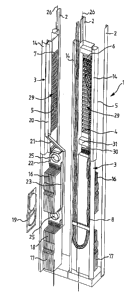
As illustrated in Figure 1, the optical fibre
partitioning and terminal rack forms a switching assembly for
optical fibre telecommunication and data cables and comprises
a rack 1 with several bays of equal width, each formed between
two vertical struts 2. In each bay, a respective frame 3 is
pivotably supported about a respective vertical axis 26. Each
frame 3 is preferably modular in construction, and formE:d of
two lateral spars 14 which extend the full vertical length
of the frame 3. Several transverse struts (not shown) are
attached between the spars 14 to serve as support locations.
The remaining components of the switching assembly are adapted
as modular sub-assemblies, and are also attached between the
spars 14. Thereby, any desired configuration of components
can be readily assembled by plugging together the approp~: fate
modular sub-assemblies. An example configuration is desci_-ibed
as follows.
Each frame 3 includes a jumper field 29 with front
and back patch fields 6, 7 accessible on the front and back
sides 4, 5 (respectively) of the frame 3. The patch fields
6, 7 are formed by a support plate 28 provided with tri-
angular recesses. The patch fields 6, 7 permit
interconnection, as shown in Figure 3, of incoming and
outgoing optical fibres 8, 9, which are connected via pigtails
10, 1l to optical fibre couplings 12, 13.
Each pigtail 10, 11 consists of a plug connector 32,
33 respectively, with a connected optical fibre 8 or 9,
respectively. The optical fibre couplings 12, 13 arE_, as
shown in Figure 3, connected through the patch fields 6, 7.
CA 02079144 2001-07-31
The front 4 of the frame 3 is closed underneath the front
patch field 6, and the spars 14 are adapted such that over-
lengths of the exchange cable can be guided and received
therebetween, as is shown on the right-hand side of Figure 1.
5 On the back 5 of the frame 3, underneath the back
patch field 7, two magazines 16, 17 are mounted. Each
magazine includes a number of slide-in openings 18 for splice
cassettes 19. The slide-in openings extend parallel to the
back 5 of the frame and substantially vertically as
illustrated in Figures 1 and 2. As illustrated, each magazine
16, 17 receives several splice cassettes 19, which are
illustrated in position in their respective magazines. One
cassette 19 is shown, in Figures 1 and 2, outside its
respective cassette, and in position to be placed into an
opening in the magazine to illustrate the fact that, with the
frame 3 in the open position (as shown on the left side of
Figure 1) , a cassette can be easily installed in (and removed
from) its magazine from a position in front of the rack 1.
Guides 20 to 24 and reorientation devices 25 for the optical
fibres 8, 9 are provided in the frame 3, to guide the optical
fibres 8, 9 between the splice cassettes 19 (in the magazines
16, 17) and the patch fields 6, 7, in such a manner as to
minimize handling and stress on the fibres.
As is shown on the right-hand side of Figure 1, in
the closed condition of the frame 3, only the patch field 6
located on the front 4 of the frame 3, and a termination field
with terminal blocks 31 for connecting copper wires, if
present, are accessible. In this condition, only the
pigtails 10 of optical fibres 8 or 9, respectively, and the
30 optical fibre couplings 12, (and the non-shown copper wires)
are exposed, while all of the other cables and components are
protected behind the frame 3. In the open position of the
frame 3 (shown on the left-hand side of Figure 1), the frame
3 is pivoted out by approximately 90°, and the patch field 7
located on the back 5 of the frame 3 and the two magazines 16,
17 of splice cassettes 19 are accessible, so that spl.ice-
CA 02079144 2001-07-31
6
cassettes can be readily removed from the slide-in openings
18 and can be slid back thereinto.
In Figures 2 and 4 , the arrangement and the guiding
of the exchange office fibre-optic cables A terminated in the
jumper plane 35 over couplings 12, 13, of the local fibre
optic cables B terminated in the upper cassette plane 36 over
a splice cassette 19 supported in the magazine 16, and of the
interoffice fibre-optic cables C terminated in the lower
cassette plane 37 over a splice cassette 19 supported in the
magazine 17 are shown. The optical fibres are connected with
each other, in the splice cassettes 19, over splices 38.
Exchange office fibre-optic cables A are conducted from the
jumper plane 35 to the upper cassette plane 36 as well as to
the lower cassette plane 37, i.e. from the jumper plane 35 to
the interoffice plane in the lower cassette plane 37.