Note: Descriptions are shown in the official language in which they were submitted.
~~'~94~8
WO 91/15890 PCT/US91/01523
1
TITLE
ARCING FAULT DETECTOR
BACKGROUND
Arcing faults cause many fires in homes, busi-
nesses, and industrial plants. Such faults often go
undetected by conventional fault detectors that respond only
to abnormally high levels of current in a circuit. For
example, circuit breakers do not trip unless an amount of
current above their rated value is sustained in their circuit.
In contrast to other types of faults (e. g., bolted
faults) which can be detected by conventional circuit
breakers, arcing faults occur periodically for only short
time intervals and generally do not support very high levels
of average fault current in a circuit. Nevertheless, arcing
faults can produce sparks which measure 10,000 degrees centi-
grade or more. Thus, although arcing faults may not support
readily detectable fault currents, arcing faults can produce
sparks that are capable of starting many fires.
Like bolted faults, arcing faults may occur either
between two wires or between a wire and ground. However,
unlike bolted faults, an air gap separates the two wires or
the wire and ground between which arcing fault currents must
pass. Accordingly, a substantial voltage across the gap is
required to overcome resistance of the gap and to permit
current to pass through the gap. Current flow across arcing
faults is relatively short lived because the voltage of
conventional alternating current circuits (AC circuits) peri-
odically reverses polarity and drops below a value needed to
sustain current flow through the fault gap. Also, the cur-
rent lags behind the voltage in phase angle and takes time to
rise to a maximum value through the gap. Together, these two
characteristics of arcing faults significantly limit the
average amount of current that can flow through an arcing
WO 91 / 15890 PCT/US91 /01523
- 2 _
fault gap. Such low levels of average current may not be
easily distinguished from other amounts of current that or-
dinarily flow through the circuit.
One previous attempt to detect lower levels of
fault current that might be associated with arcing faults is
disclosed in U.S. Patent 3,911,323 to Wilson et al. A tran-
sistor amplifier is used to make the conventional detection
equipment more sensitive to ground fault currents. Ini-
tially, only a warning signal is given in response to the
detection of possible fault currents that are not of a suf-
ficient magnitude to trip a circuit breaker. However, if the
fault current persists and increases to a substantial level,
a ground fault indicator is used to trip a circuit breaker.
Although the known fault detector may indicate the
presence of arcing faults to ground, other types of arcing
faults (e. g., wire-to-wire faults) go undetected. Further,
the detector of Wilson et al. permits arcing faults to con-
tinue unabated for a considerable period of time. A fire may
be started by the fault well before the fault current raises
to the substantial level at which the circuit is interrupted.
Nevertheless, it would not be a good idea to modify
the detector of Wilson et al. to interrupt the circuit in
response to a possible ground fault any sooner. Other ordi-
nary circuit disturbances can produce erroneous indications
of a temporary ground fault. Moreover, it is a very serious
matter to cut off the power to a circuit, and such a step
should not be taken unless there is a clear presence of a
fault. In a household circuit, the interruption of power
shuts off the supply of heat, refrigeration, and lights; any
one of which can have serious consequences. Valuable data in
active computer memory can also be lost by an unexpected
power loss at businesses. Further, in an industrial plant, a
sudden power loss can damage equipment or parts in manufac-
ture, and can pose a significant safety hazard.
i 2079468
- 3 -
In addition to supporting fault current, arcing
faults also exhibit a variety of other electrical
characteristics. However, many of the same or similar
characteristics can be exhibited by other circuit disturbances
that do not warrant cutting off the supply of power to the
circuit. Accordingly, it has been a general practice to
merely activate some form of alarm in the presence of faults
that involve only small leakages of current rather than to
immediately cut off the supply of power. As a result, most
households, businesses, and industrial plants are not very
well protected against arcing faults and are subject to
electrical fires that are started before conventional fault
detection equipment cuts off the supply of electrical current
to the fault.
SiTMMARY OF THE INVENTION
My invention overcomes the above-described problems
with the prior art by providing a new fault detector that
quickly identifies and distinguishes arcing faults from other
circuit disturbances and interrupts the supply of electrical
power to the circuit in which an arcing fault is detected.
Arcing faults are identified and distinguished from other
types of circuit disturbances by monitoring the circuit for a
plurality of conditions that are characteristic of arcing
faults and by combining the state of those conditions in a
prearranged logic circuit. An output signal from the logic
circuit indicating the presence of an arcing fault is used to
trip a circuit breaker and interrupt power to the faulted
circuit.
In accordance with one aspect of the present
invention there is provided an arcing fault detector for
protecting household, business, and industrial electrical
circuits comprising: a current transformer that produces a
signal for tracking the behavior of current in the electrical
circuit; a voltage divider that produces a signal for tracking
the behavior of voltage in the electrical circuit; a plurality
of processing circuits that isolates individual electrical
2~~9468
- 3a -
characteristics apparent from the current and voltage tracking
signals and that tests the individual electrical
characteristics against predetermined parameters bearing
respective logical relationships to the presence of an arcing
fault in the electrical circuit; comparators within each of
said processing circuits that register the outcome of the
tested electrical characteristics as logical condition
signals; a logic circuit that combines the logical condition
signals with a logical "or" gate, and that produces an output
signal which registers not less than all actual arcing faults
that fulfill any one of the logical conditions and not more
than all non-fault disturbances that fulfill any one other of
the logical conditions; and means for interrupting electrical
power to the electrical circuit in response to a logical state
of the output signal.
In accordance with another aspect of the present
invention there if provided an arcing fault detector for an
electrical circuit comprising: a current transformer for
producing a signal tracking the behavior of current in the
electrical circuit; a voltage divider for producing a signal
tracking the behavior of voltage in the electrical circuit; a
first timer for comparing a phase relationship between the
voltage tracking signal and current tracking signal; a second
timer for identifying a timed interval in the vicinity of the
usual peak voltage of the voltage tracking signal; a
comparator for identifying a reduced voltage within the timed
interval with respect to the usual peak voltage; a high pass
filter for identifying an occurrence of a high frequency
disturbance in the current tracking signal; and a logic
circuit for combining conditions relating to (a) the phase
relationship between the voltage tracking signal and current
tracking signal, (b) the voltage within the timed interval,
and (c) the frequency of disturbance in the current tracking
signal, and for producing an output signal indicating the
presence of an arcing fault in the electrical circuit.
In accordance with yet another aspect of the present
invention there is provided an arcing fault detector for
2079468
- 3b -
interrupting the supply of electrical power to a circuit
comprising: means for producing a signal tracking the
behavior of current in the circuit; means for producing a
signal tracking the behavior of voltage in the circuit; means
for processing at least one of the signals tracking the
respective behaviors of current and voltage in the circuit,
and for identifying a first electrical characteristic bearing
a logical relationship to the presence of an arcing fault in
the circuit as one of a nonexclusive condition, a noninclusive
condition, and a nonexclusive-noninclusive condition; means
for processing at least the other of the signals tracking the
respective behaviors of current and voltage in the circuit,
and for identifying a second electrical characteristic bearing
a logical relationship to the presence of an arcing fault in
the circuit as one of a nonexclusive condition, a noninclusive
condition, and a nonexclusive-noninclusive condition; means
for producing a logical output signal by logically combining
the one of the logical conditions relating to the first
electrical characteristic with the one of the logical
conditions relating to the second electrical characteristic
according to one of the following rules wherein: - two
noninclusive conditions are combined with a logical "or",
- a nonexclusive-noninclusive condition and one of a
nonexclusive condition and another nonexclusive-noninclusive
condition are combined by a logical "and" defining an
effective noninclusive condition, and - a nonexclusive-
noninclusive condition and one of a noninclusive condition and
another nonexclusive-noninclusive condition are combined by a
logical "or" defining an effective nonexclusive condition; and
means for interrupting the supply of electrical power to the
circuit in response to a logical state of the output signal.
The logic may be preset to provide protection for a
number of different circuit configurations or may be set to
accommodate the special circumstances of a particular circuit.
The important decision to interrupt the protected circuit is
made by the logic circuit based on a plurality of monitored
conditions relating to known electrical characteristics of
arcing faults. The monitored conditions are
207~4~~
WO 91/15890 PCT/US91/01523
- 4 -
logically combined to identify arcing faults and to dis-
tinguish the arcing faults from other anticipated electrical
disturbances which may exhibit one or more similar electrical
characteristics in the protected circuit.
Some of the monitored electrical characteristics
may be exhibited by all arcing faults, but the same elec-
trical characteristics may be exhibited by other circuit
disturbances as well. These characteristics establish
nonexclusive conditions. Other of the monitored character-
istics may be exhibited by only arcing faults or other types
of faults, but not all arcing faults may exhibit these char-
acteristics. These other monitored characteristics establish
noninclusive conditions. Yet other monitored characteristics
may be generally exhibited by most arcing faults but not all,
and may only rarely be exhibited by other circuit distur-
bances. These yet other characteristics establish
nonexclusive-noninclusive conditions.
Preferably, the nonexclusive conditions are com-
bined by a logical "and" gate in the logic circuit to further
exclude disturbances that exhibit only one of the character-
istics that establish the respective nonexclusive conditions.
The noninclusive conditions are preferably combined by a
logical "or" gate to further include arcing faults that ex-
hibit only one of the characteristics that establish the
respective noninclusive conditions. However, it is generally
not preferred to combine nonexclusive and noninclusive
conditions or even to further combine groups of combined
nonexclusive and noninclusive conditions in the same logic
circuit unless a nonexclusive-noninclusive condition is
present.
The nonexclusive-noninclusive conditions may be
combined with either a nonexclusive or another nonexclusive-
noninclusive condition by a logical "and" for effectively
establishing a single noninclusive condition. Similarly, the
nonexclusive-noninclusive conditions may be combined with
~~'~~~6~
WO 91/15890 PCT/US91/01523
- 5 -
either a noninclusive or another nonexclusive-noninclusive
condition by a logical "or" for effectively establishing a
single nonexclusive condition. Thereafter, the effective
conditions can be combined with a like condition or another
like effective condition as explained above.
A wide variety of electrical characteristics are
exhibited by at least some arcing faults. Many of these
characteristics can be detected by monitoring source values
of voltage and current in a circuit. For example, arcing
faults exhibit very low power factors. Typically, the cur-
rent lags behind the voltage by a phase angle of 85 degrees
or more when an arcing fault is present. The resulting power
factors (Cosine 85 degrees) are less than .1. Other circuit
disturbances, accompanying such events as the starting of
motors or fluorescent lights, may also exhibit reduced power
factors. Nevertheless, power factors less than .1 are
generally reserved to faults On the other hand, not all
arcing faults exhibit power factors less than .1. Accord-
ingly, the characteristic of a circuit power factor less than
.1 may be regarded as a noninclusive condition.
Another characteristic of arcing faults relates to
a voltage drop that accompanies the flow of current across an
arcing fault gap. Once the instantaneous voltage across the
gap reaches a spark-over value (i.e., the voltage required to
induce current flow across the gap), the voltage drops off to
a relatively constant level that is required to sustain the
flow of current across the gap. The voltage remains rela-
tively constant until after the voltage reverses polarity.
One condition that may be derived from this char-
acteristic relates to comparing the usual peak voltage of the
circuit to the actual circuit voltage in the timed vicinity
of the usual occurrence of the peak voltage. For example,
peak voltages usually occur at 90 degree phase angles from
the zero crossing point of the voltage. Voltage associated
with the occurrence of an arcing fault is significantly re-
WO 91/15890 PCT/US91/01523
2079468 -6 -
duced in the vicinity of the 90 degree phase angle. However,
it is preferred to monitor the voltage within a short inter-
val that extends slightly beyond 90 degrees to include arcing
faults having spark-over values up to the usual peak voltage
at 90 degrees. The interval is kept short to limit the
amount of time available for another disturbance to affect
the monitored voltage. It is also preferred to select a
threshold voltage value, beneath which an arcing fault is
indicated, and just above the expected voltage value required
to sustain a current across the arcing fault gap in the
circuit.
The above-mentioned parameters of phase angle, time
interval, and threshold voltage value are generally set to
include most arcing faults and exclude most other distur-
bances. This establishes a nonexclusive-noninclusive
condition. However, the same parameters may be adjusted for
a particular circuit to establish either a nonexclusive or
noninclusive condition. Also, the same electrical character-
istic can be monitored differently to establish, for example,
a more exclusive condition by either requiring the reduced
voltage value to be maintained for a period of time or
requiring the initially reduced voltage to be maintained
above a predetermined value in the vicinity of the point at
which the voltage ordinarily reverses polarity.
Another characteristic of arcing faults is the
presence of a DC component of the monitored alternating cur-
rent circuit. The DC component includes a very fast rise
time in the event of an arcing fault and is registered in the
current as a very high frequency disturbance. All arcing
faults are believed to exhibit such high frequency distur-
bances, but such disturbances are not necessarily limited to
arcing faults. Accordingly, the presence of a high frequency
disturbance establishes a nonexclusive condition.
WO 91/15890
PCT/US91 /01523
-
Apparatus provided by my invention for monitoring a
circuit for arcing faults includes a current transformer and
a voltage divider for respectively isolating the behavior of
current and voltage in the circuit. Output signals from the
two devices are in the form of very low voltages that vary in
accordance with the current and voltages in the circuit. The
output signals are processed by a plurality of circuits that
isolate electrical characteristics of the monitored circuit
and that include test parameters for establishing conditions
that identify particular electrical characteristics as
bearing respective logical relationships to the presence of
an arcing fault in the monitored circuit. Analog-to-digital
comparator means is used to register the established condi-
tions as digitally processable values. A logic circuit
combines the digitally registered conditions to produce an
output signal indicating the presence of an arcing fault in
the monitored circuit. At a minimum, the output signal of
the logic circuit registers not less than the number of
actual arcing faults fulfilling any one of the logical
conditions and not more than the number of non-fault distur-
bances fulfilling any other condition. However, it is
preferred to provide a combination of conditions whereby the
output signal also registers less than the number of non-
fault disturbances that fulfill any one condition. A relay
operable in response to the output signal of the logic cir-
cuit provides for arming an alarm and for interrupting the
supply of power to the monitored circuit.
My invention provides important protection for
household, business, and industrial electrical circuits by
more consistently identifying arcing faults within a level of
confidence whereby it is appropriate to interrupt power to
the protected circuit. The presence of arcing faults may
also be detected before a second strike can occur, and the
power is interrupted before most fires can have a chance to
start.
2079468
_8_
DRAWINGS
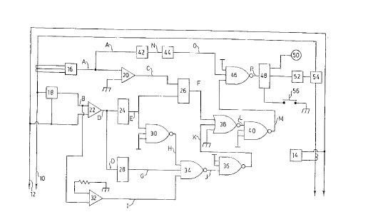
Figure 1 is a schematic diagram of a circuit that
may be used in accordance with the present invention for
detecting arcing faults, arming an alarm and interrupting the
supply of power to the affected circuit.
Figure 2 is a timing chart which shows the
comparative progress of different signals advancing through
the circuit of Figure 1.
Figures 3A through 3D depict a set of rules for
combining logical conditions relating to the presence of
arcing faults.
DETAILED DESCRIPTION
My invention is depicted in FIG. 1 monitoring a
typical (e.g., 120 volt) household circuit. Power line 10 and
neutral line 12 convey alternating current supplied by power
source 14. Although shown as a block within my circuit
diagram, power source 14 may represent a commercial power
source very remote from my depicted circuit.
My detector is connected to the household circuit by
current transformer 16 and voltage divider 18. Respective
output signals A and B, shown also in FIG 2, track the
respective behaviours of current and voltage in the household
circuit. The tracking is accomplished by small variations of
voltage in the respective signals. For example, the signals
may vary in voltage between zero and 5 volts.
Analog-to-digital comparators 20 and 22 respectively
compare the signals A and B to a zero, ground, or neutral
reference voltage and output high logic condition signals when
the signals A or B exceed the zero reference voltage. For
example, as shown in FIG. 2, both output signal C from
comparator 20 and output signal D from comparator 22 assume a
high logic condition when respective tracking signals A and B
exhibit positive voltages.
WO 91/15890
PCT/US91 /01523
- 9 -
The leading edge of a high logic signal D starts
timer 24. Output signal E from the timer is programmed to
remain high until a predetermined time interval has elapsed
since the timer was started. The predetermined time interval
is set to correspond to a minimum phase angle between the
leading edge of voltage signal D and the leading edge of cur-
rent signal C beyond which a low power factor of an arcing
fault is indicated.
The signals C and E are connected to a conventional
flip-flop arrangement 26. The leading edge of current signal
C entering the flip-flop arrangement enables flip-flop output
signal F to track the inverse of timer signal E. For
example, flip-flop signal F assumes a high logic condition
when the leading edge of current signal C enters the flip-
flop arrangement after the interval timed by timer 24 has
elapsed. Accordingly, a high logic condition of flip-flop
signal F indicates that the power factor of the monitored
circuit is less than a predetermined amount controlled by the
interval timed by timer 24. Preferably, the timed interval
is set so that the signal F indicates power factors less than
or equal to .1 and thereby excludes all non-fault distur-
bances. However, since it is possible for certain arcing
faults to exhibit power factors greater than .1, the signal F
may be understood to register a noninclusive condition of an
arcing fault.
The leading edge of voltage signal D is also used
to start timer 28. Output signal G of timer 28 is programmed
to remain in a high logic condition until a timed interval,
extending slightly beyond a 90° phase angle of voltage signal
B, has elapsed. The output E from the other timer is in-
verted by "nand" gate 30 to a signal H that reflects a high
logic condition when the time limit of timer 24 has been
exceeded. Accordingly, a high logic condition of both timer
signals G and H indicates a period of time during which the
interval timed by timer 28 exceeds the timed interval of
timer 24. This period is set to include the 90 degree phase
20 794 68
"~''O 91/15890 PCT/US91/01523
- 10 -
angle of voltage signal B at which the usual peak voltage of
the signal occurs.
The output signal B from voltage divider 18 is also
connected to another analog-to-digital comparator 32. How-
ever, instead of comparing the signal B to a zero reference
voltage, the comparator 32 compares the signal B to a prede-
termined maximum reference voltage and outputs a high logic
signal I in response to signal voltages that are less than
the predetermined reference voltage. The logic conditions G,
H, and I are combined at "nand" gate 34 to ascertain the
presence of another electrical characteristic of the moni-
tored circuit which bears a logical relationship to the
presence of an arcing fault. Signal J from the output lead
of the "nand" gate 34 assumes a low logic condition only when
all of the input signals G, H, and I are high. This means
that the signal J is low only when a predetermined voltage
drop has occurred in the vicinity of the usual peak values of
the voltage signal.
The reference voltage of comparator 32 is set lower
than most disturbances that may occur in the vicinity of the
peak voltage and higher than most voltages required to
sustain arcing faults in the monitored circuit. Accordingly,
the signal J registers a nonexclusive-noninclusive condition
of an arcing fault. Thereafter, the signal J is inverted by
"nand" gate 36 into a signal K that registers the same result
as a high logic condition.
The low power factor signal F is combined with
voltage drop signal K at "nor" gate 38. Output signal L of
"nor" gate 38 is low whenever either signal F or K is high.
The signal L is then inverted by "nand" gate 40 to a signal M
so that the logical state of signal M reflects the combina-
tion of the noninclusive condition of signal F and the
nonexclusive-noninclusive condition of signal K by a logical
"or". As a result, the signal M registers an effective
nonexclusive condition, the high state of which is more
inclusive of actual arcing faults than either signal F or~K
vVO 91/15890 I ~ ~ ~ ~ ~ ~ ~ PCT/L1S91/01523
- 11 -
and is no less exclusive of other disturbances than logic
signal K alone.
Signal A, which tracks the behavior of current in
the monitored circuit, is also connected to high pass filter
42. The filter is of a conventional type which permits only
high frequency current in the range of frequencies exhibited
by arcing faults to pass through the filter (e. g., 5000
hertz). Output signal N from the filter takes the form of a
momentary burst of current in the presence of a high fre-
quency disturbance in the monitored circuit. Amplitude
demodulator 44 receives the signal N and outputs a logical
condition signal O that retains a high value for a longer
duration of time than signal N. The duration of signal N is
extended by signal O to enable any output of filter 42 to
arrive contemporaneously at "nand" gate 46 with the signal
M. The high frequency threshold of filter 42 is selected so
that logic signal O exhibits a high condition in the presence
of any arcing fault. However, it is possible for other
disturbances to also impact the current with similar high
frequencies. Accordingly, the logic condition O is regarded
as registering a nonexclusive condition of an arcing fault.
The "nand" gate 46 combines the nonexclusive logic
condition O with the effective nonexclusive condition M and
outputs a signal P that assumes a low state only if both
logic conditions O and M exhibit high states. Although the
output of signal P is the inverse of the combination of the
same two condition signals by a logical "and", the state of
signal P reflects the same information that would be avail-
able from its inverse representation. Accordingly, the
combination of the conditions 0 and M by the equivalent of a
logical "and" results in a low logic condition of output
signal P that is more exclusive of other disturbances than
either condition O or M. Furthermore, since the condition M
is nonexclusive, the low condition of signal P is also more
inclusive than either condition F or K. Together, this two
stage logical combination of three condition signals (F, K,
'O 91 / 15890 7 9 ~ 6 8 PCl"/US91 /01523
- 12 -
and O) provides greater assurance that actual arcing faults
will be detected and other disturbances will not be mis-
takenly detected as arcing faults.
The signal P enters latching circuit 48 that is
switched to an activating condition by any occurrence of a
low condition of signal P until reset by switch 56. Latching
circuit 48 activates both alarm diode 50 and relay 52. Cir-
cuit breaker 54 is tripped by relay 52 whenever the latching
circuit is switched to an activating condition. In other
words, the low logic condition of signal P provides for in-
terrupting the supply of power to the household circuit in
the clear presence of an arcing fault.
Although my invention has been described with only
particular electrical characteristics of the circuit being
monitored and with particular parameters establishing
logical conditions for deciding on the presence of an arcing
fault, it would be possible to monitor the circuit for other
characteristic behaviors of arcing faults and to use other
parameters for establishing other combinations of logical
conditions to identify and distinguish arcing faults. Fur-
thermore, although the depicted circuit includes a
particular combination of well-known electrical components,
it may be appreciated that all of the digital functions of
my circuit may be accomplished by equivalent means within a
programmable controller. Such a controller could also be
used to more readily amend the logic of the circuit to
accommodate the requirements of a different circuit.
Alternatively, the conditions F, K, and O could be input to
a conventional decoder which would enable the selection of
other logical combinations between the conditions by
activating switches.
FIGS. 3A through 3D depict basic rules for
combining the logical conditions in respective block
diagrams. For example, FIG. 3A shows two nonexclusive
conditions 60 and 62 combined by a logical "and" block 64,
whereas FIG. 3B shows two noninclusive conditions 66 and 68
combined by a logical "or" block 70. In FIG. 3C, a
~;,:,: s
279468
- 13 -
nonexclusive-noninclusive condition 72 is combined with one
of a nonexclusive condition 74 and another nonexclusive-
noninclusive condition 76 by a logical "and" block 78
establishing an effective noninclusive condition 80.
Thereafter, a noninclusive condition 82 is combined with the
effective noninclusive condition 80 by a logical "or" block
84, according to the rule depicted in FIG. 3B. In FIG. 3D,
a nonexclusive-noninclusive condition 86 is combined with
one of a noninclusive condition 88 and another
nonexclusive-noninclusive condition 90 by a logical "or"
block 92 establishing an effective nonexclusive condition
94. Thereafter, a nonexclusive condition 96 is combined
with the effective nonexclusive condition 94 by a logical
"and" block 98, according to the rule depicted in FIG. 3A.
In a more general sense, it may be appreciated
that although the depicted circuit is connected to an
ordinary 120 volt system, it would also be possible to
connect my device to any standard system (e. g., 120/240,
120/208, 277/480, 2400/4160, and 7200/12,500, etc.).
Line-to-line protection requires additional current
transformers and voltage dividers for monitoring the
additional lines, but the same detection circuitry can be
used to identify and distinguish arcing faults between the
lines. For example, two wire single-phase circuits require
one detection circuit, three wire single-phase circuits
require two detection circuits, and three wire and four wire
three-phase circuits require three detection circuits.