Note: Descriptions are shown in the official language in which they were submitted.
~d 2
- 1 -
APPARATUS FOR THE TEMPORARY STORAGE AND CONTROLLED FEXDING OF
VOLATILE FUEL COMPONENTS INTO THE INTAKE MAMIFOLD OF AN
INTERNAL COMBUSTION ENGINE
This disclosure relates to an apparatus for the temporary storage
and controlled feeding of volatile fuel components present in the
unfilled space of a liquid fuel tank into the intake manifold of an
internal combustion engine.
Gonventional apparatus for the temporary storage and controlled
1~ feeding o~ volatile fuel components generally have a vent line which
connects the unfilled space above the liquid with the atmosphere and
includes a storage chamber provided with an absorption element. A
conduit which can be closed by an electromagnetic shut-off valve
connects the storage chamber with the intake manifold. The valve has an
inlet port and at least one outlet port, with a main valve seat and an
auxiliary valve seat provided between the intake and outlet ports. The
auxiliary valve seat can be closed by a vacuum actuator which is
operable by a pressure difference with the atmosphere.
Such an apparatus is known, for exampleJ from German published
application DE-OS 3909887. That application discloses a process for the
checking of the operability of a tank ventilation valve as described
above through which an additional amount of air loaded with fuel vapors
~an be provided to the intake region of an internal combustion engine.
Satisfactory operating characteristics are not achievable over the whole
load range of the internal combustion engine, since the pressure in the
intake manifold varies depending on the respective load condition of the
engine. The apparatus, and especially the valve disclosed cannot be
used in connection with a boosted, blown or supercharged internal
combustion engines.
3~ It is now an object of this disclosure to provide an apparatus as
described above, which can be used in connection with boos~ted internal
combustion engines, is easily and economically manufactured, has compact
dimensions and has good operating characteristics over a long service
period.
This ob~ect is achieved in an apparatus as described above which is
adapted for use with an internal combustion engine, wherein the valve
~' :
.
:: :
2~
-- 2 --
has two outlet ports. One of the outlet ports is connected to the low
pressure section of the booster and the other outlet port is connected
to the intake manifold. The term ~booster" used in this disclosure
generally refers to a compressor, which1 for example, may be a
turbo-charger, a mechanically driven G-charger or a Roots blower. The
outlet ports are respectively provided with first and second check
valves which open towards the booster and the intake manifold
respectively. This apparatus is of simple construction and expensive
switching arrangements which can disturb reliable operation of the
1~ apparatus are obviated. Furthermore, the apparatus is distinguished ln
that it includes only a small number of connected components and that
the switching from induced or vacuum to boosted operation is
automatically achieved. The vacuum actuator membrane control provides
for a finely metered dosage of the amount of volatile fuel components
passing through the value during vacuum operation at engine idle. The
first outlet port of the valve is only connected to the low pressure
section of the booster and the second outlet port is connected only to
the intake manifold downstream of the throttle valve. This construction
of the valve also provides the apparatus with good operating
characteristics.
At idle and during manifold vacuum operation of the internal
combustion engine, the auxiliary valve seat is maintained completely or
almost completely closed by the vacuum actuator to limit the flow of
volatile fuel components into the region between throttle valve and
~5 engine~ During vacuum operation at partial load, the feed of volatile
~uel components into the intake manifold is controiled by the vacuum
actuator which operates on the pressure differential existing between
the valve's interior and the atmosphere. During boosted operation at
partial or full load, the maximum possible feed of volatile fuel
components from the absorption element to the engine is required and a
super-atmospheric pressure will generally be present in the intake
manifold. The first check valve of the first outlet port is
automatically closed by this over pressure, which reliably prevents
short circuiting through the valve. The sPcond check valve of the
second outlet port is open in this operating condition of the engine,
the volatile fuel components are fed through the second outlet port to
.
;
- 3 ~
the booster whence the volatile fuel components and the fuel/air mixture
are ~ransported under pressure into the engine combustion chambers. The
main valve seat is provided with an electric drive, which is preferably
connected ~or signal transmission with a diagnosis block. The diagnosis
block has signal output and input connections, for monitoring accurate
operation of the apparatus. The input data may be index values which
are already available for use by an electronic engine management system
of the engine. To allow visual monitoring of the apparatus,
irregularities within the apparatus are indicated on an appropriate
display when a selected threshold value, which represents the tolerance
between the measured value and a theoretical value, is exc~eded.
In a preferred embodiment, the first outlet port is coordinated
with the auxiliary valve seat and the second outlet port is coordinated
with the main valve seat. This is advantageous since by bypassing the
vacuum actuator during operation at load, higher amounts of volatile
fuel components can be removed from the absorption element, since fewer
flow restrictions are present. The check valves of the outlet ports are
preferably elastomeric components known in the art.
To achieve improved operating characteristics for a long service
~0 period, the auxiliary valve seat can be closed by elastomeric material
carried by a vacuum actuator. The vacuum actuator preferably has a
supporting collar which on one side contacts a set membrane constructed
as a rolling membrane and on the other a compression spring. The
construction of the set membrane as a rolling membrane reliably prevents
~5 tensions in the membrane leading to breakage and thus extends it service
life. This construction of the set membrane also provides an especially
fine control of the flow of volatile fuel components through the
auxiliary valve seat.
In a particularly preferred embodiment, the check valves are spring
loaded and operable by a pressure differential across them. In the
condition of the apparatus where no pressure difference is present, the
check valves respectively automatically engage a sealing seat provided
at each of the outlet ports thereby closing the outlet ports. The check
valves may, for example, be spring loaded ball valves, or elastically
deformable tongue valves, which, when no pressure difference is present>
contact the sealing seat under elastic pretension. The vacuum actuator
z~
-- 4 --
may operate against the spring force of a compression spring positioned
in ehe valve. This construction provides good adaptation to the
respective conditions of different applications. A valve of the same
principle of construction may be relatively easily adapted for use with
different internal combustion engines and fuel tank units by using
compression springs with a different characteristic elasticity curve.
The main valve seat may be provided with an electric drive, whereby
the drive has electrical contacts which are connected with the diagnosis
block for signal transmission. This is advantageous in that reliable
m~nitoring of the apparatus can be achieved. The diagnosis block, which
may be part of a characteristic field of an engine management system
controls the opening cross-section of the main valve seat and, thus, the
flow of volatile fuel components into the intake manifold of the
internal combustion engine and that in accordance with the most diverse
lS input parameters. For easy monitoring of the apparatus, the diagnosis
block may be connected with control instruments which may be integrated
into the ~ashboard of the vehicle. When a selected threshold value is
exceeded, which threshold value represents the difference between a
theoretical value and the measured value of a selected parameter, visual
and/or acoustic signals may call attention to this discrepancy. The
input signal of the diagnosis block may represent, for example, the
position of the throttle valve, the rotational speed of the internal
combustion engine, various temperatures and pressures within and about
the engine as well as the exhaust composition. Other input and output
variables are also conceivable.
Embodiments of the invention will now be further described by way
of example only and with reference to the attached drawings, wherein
Figure 1 is a schematic diagram of a preferred apparatus as
disclosed herein used in connection with a boosted internal combustion
3~ engine; and
Figure 2 is a preferred embodiment of a valve which can be used in
an apparatus as shown in Figure 1.
The arrangement schematically illustrated in Figure 1 includes an
apparatus in accordance with this disclosure and an internal combustion
engine 4, which has an intake manifold 3 and is fed by a hooster 16. A
throttle valve 22 is positioned in the intake manifold 3. The air feed
,
~ `:
- 5 ~ r~ ~
-
for the internal combustion engine 4 is first passed through an air
filter 23. ~ valve 10 of the apparatus is only schematically
illustrated in Figure 1 and is represented only by its outer contours.
The valve 10 has two outlet ports 12.1 and 12.2 and one inlet port 11
which is connected by a conduit 9 with an absorption element 8 located
in storage chamber 7. Volatile fuel components present in the unfilled
space 1 of a fuel tank 2 reach the absorption element 8 through a vent
line 6. Whether the internal combustion engine 4 operates under induced
or boosted conditions, the volatile fuel components from the unfilled
space 1 and the absorption element 8 reach the valve 10 through conduit
9~ During induced vacuum operation, the volatile fuel components flow
through the first outlet port 12.1 and are sucked into the engine 4 by
virtue of the vacuum present in the intake manifold 3. The volatile
fuel components are in that case fed into the intake manifold 3
downstream of the throttle valve 22. During boosted operation however,
at partial or full load, where a relative over pressure exists in intake
manifold 3, a first check valve 17 (Figure 2) stops the flow through the
first outlet port 12.1 and the volatile fuel components flow around a
sacond check valve 18 at the auxiliary outlet port 12.2 and towards the
~a charger 16. Thus, the volatile fuel components from the unfilled space
1 and the absorption element 8 are carried to booster 16, which
compresses them and transports them under over pressure into the
combustion chambers of the internal combustion engine 4. A diagnosis
block 21 and a display instrument 24 are used for monitoring and control
of the apparatus embodying the invention. The flow of volatile fuel
components through the main valve seat 13 is controlled by the electric
driva 20 depending on input variables, which drive is connected for
slgnal transmission from the diagnosis block 21.
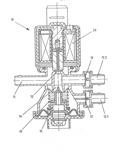
Valve 10 of the apparatus shown in Figure 1 is illustrated
3a separately and in cross-section in Figure 2. The valve 10 has a drive
20 for actuating the main valve. The drive 20 is connected with
diagnosis block for signal transmission (see Figure l) and controls the
flow through the valve seat 13 depending on the parameters~input into
the diagnosis block. A vacuum actuator 15 controls the~flow through the
auxiliary valve seat 14 and is operated by a pressure difference. The
outlet ports 12.1 and 12.2 are respectively provided wlth check valves
- 6 - 2~ ?~
17 and 18. The check valves in this embodiment are elastically
deformable tongue valves, however, spring loaded ball valves may also be
used. Externally operated switching of the check valves within the
outlet ports 12.1 and 12.2 is obviated with this construction. The
auxiliary valve seat 14 is conical and can be provided, as required,
with a conical closure member made of elastomeric material.
The apparatus embodying the invention is characterized by a simple
construction, a small number of components and economical manufacture.
Furthermore, ~ood operating characteristics of the apparatus are
1~ guaranteed for a long service period where the apparatus is used with a
boosted internal combustion engine.
.
- :. . . ,,, , : , :