Note: Descriptions are shown in the official language in which they were submitted.
- 1- 2~79~40
DOUBLE END~D HOLLOW FIBER BUNDLE AND
FLUIDS SEPARATION APPARATUS
Field of ~he Invention
5This invention relates to a double ended
hollow fiber bundle and to a four port fluids
separation device or apparatus for the separation of
a fluid component from a feed comprising a mi~ture of
fluids. It also relates to a three port fluids
10 separation device. The term mixture of fluids as
used throughout this specification refers to a
mixture of liquids and/or a mixture of gases. In one
embodiment for countercurrent flow arrangement it
pertains to a fluid separation apparatus that allows
15 for the introduction of the feed into the shell side
of the hollow fiber separation apparatus, flow of the
feed through the entrance regions into contact with
the outside surface of the hollow fiber permselective
membrane bundle, removal of permeate component from
20 the open bores at both ends of the hollow fiber
membrane bundle and removal of non-permeate component
via an e~traction tube, the separation being carried
out while maintaining a countercurrent flow
arrangement along the entire length of the hollow
25 fibers bundle. Further embodiments are also
described in this specification.
Descri~tion of the Prior art
Numerous disclosures e~ist on the various
30 types of devices used for separating fluid mixtures
with hollow fiber membranes. In most fluid
separations essentially three streams are present, a
D-16718
2~7~0
-- 2
feed stream, a permeate stream and a non-permeate
stream. Thus the permeator will usually require a
total of only three entry and exit ports; huwever,
four ports are occasionally used and the permeate is
5 e~tracted from two separate ports. As known, use of
a single lor~ bundle in a large, longitudinal casing
may result in excessive and undesired hollow fiber
bore-side pressure drop.
U.S. Patent No. 3,536,611, issued on
10 October 27, 1990 to R.P. deFilippi, et al., relates
to a capillary membrane device in which a net of
fibers is woven around a central distributor tube.
The feed stream is introduced into the bores of the
fibers at one end and the non-permeate is recovered
15 at the opposite end of the bundle. The permeate
flows radially to the axis of the distributor tube
and no provision is made for cocurrent or
countercurrent flows.
U.S. Patent 4,082,296, issued to G.B. Clark
20 on March 4, 1978, describes a hollow fiber permeator
in which permeate is withdrawn from two bundles
within the same shell. This invention does not teach
how permeate can be withdrawn from two ends of the
same bundle. Also, only a radial type flow pattern
25 is described.
U.S. Patent 4,622,143, issued on
November 11, 1986 to D.W. Edwards, describes a three
port permeator in which permeate is e~tracted from
both ends of a fiber bundle. However, there is no
30 indication as to how this module could be used in a
cocurrent or countercurrent flow pattern.
U.S. Patent 4,7Q7,267, issued on
November 17, 1987 to H.K. Johnson, relates to a fluid
D-16718
- 3 - 2~7~5~
separatory device made up of a bundle of hollow
fibers which are fastened at each end into a resin
tubesheet. The permeate fluid is carried out of the
separator through outlets at each end, but only a
5 radial-type flow arrangement is indicated.
A membrane separation apparatus that
comprises a hollow fiber bundle is described in U.S.
Patent 4,781,834, issued November 1, 1988 to
M. Sekino et al. The outer surface of the hollow
10 fiber package is covered by a nonpermeable film
except for a small uncovered portion. This
arrangement leads to a cocurrent or countercurrent
flow pattern. However, the permeate outlet is
limited to one end of the bundle only.
U.S. Patent g,B65,736 issued on
September 12, 1989 to M.J. Coplan, discloses a hollow
fiber separatory module in which an annular hollow
fiber bundle is encased within an impervious
barrier. While this module can be operated in either
20 a cocurrent or countercurrent flow arrangement, only
one end of the bundle can serve as the permeate
outlet.
In U.S. Patent 4,881,955, issued on
November 21, 1989 to B. Bikson et al., a wound hollow
25 fiber cartridge is described in which the feed fluid
enters the bores at one end of the bundle and the
non-pe~meate fluid exits at the opposite end of the
bundle. Both cocurrent and countercurrent flow
patterns are readily achieved with this design, but
30 the arrangement is limited to boreside feed flow
configuration.
U.S. Patent No. 4,293,419, issued on
October 6, 1981 to M. Se~ino, et al., describes a
D-16718
_ 4 _ 2 ~ 7 9 ~ 0
hollow fiber assembly in which permeate is withdrawn
from two bundles within the same pressure containment
vessel. The arrangement is limited to permeate
recovery from one bundle end only and radial flow
5 configuration, there is no provision made for
countercurrent or cocurrent flow arrangement.
Summary of the Invention
This invention relates to a double ended
10 hollow fiber bundle and to a fluids separation
apparatus (permeator) containing the double ended
hollow fiber bundle encased therein. This apparatus
can have a total of three or four, preferably four,
entry and exit ports, as discussed below. The
15 apparatus comprises a shell enclosing the annular
double ended hollow fiber bundle. As used throughout
this specification the term "double ended hollow
fiber membrane cartridge or bundle" or variant
thereof means a bundle of hollow fibers having a
20 tubesheet at both ends with the bores of the hollow
fibers open at both ends to allow the removal of
permeate fluid. A helically wound hollow fiber
membrane bundle or cartridge is the preferred
bundle. When the permeator shell contains a total of
25 four entry and exit ports they are a fluid feed
entrance port, a non-permeate exit port and two
permeate exit ports. When the permeator shell
contains a total of three entry and e~it ports they
are a fluid entrance port, a non-permeate exit port
30 and one permeate exit port. The double ended hollow
fiber membrane bundle contains a center core tube,
with hollow fibers arranged in a cylindrical shape
D-16718
- 5 - 2~79~
around the center core. Preferably the hollow fibers
are helically wound around the center core. The
center core is a hollow tube that has perforations or
holes located, preferably, at essentially the center
5 section along the longitudinal length of the center
core tube between the two tubesheets, as discussed
below. The outer surface of the hollow fiber
membranes bundle is tightly encased in an essentially
impermeable barrier material placed around
10 essentially the entire longitudinal length of the
double ended hollow fiber bundle, except for narrow
uncovered entrance regions at both ends of the hollow
fiber bundle in the areas adjacent to the tubeheets
to permit flow of fluid with the outside surface of
15 the bundle of hollow fibers for contact with the
e~terior surface of the hollow fibers. The two ends
of the hollow fiber membranes bundle are encapsulated
in tubesheets with a center core tube extending
through one of the tubesheets to permit flow of fluid
20 stream out of the hollow center core tube. Both ends
of the hollow fiber membrane bundle are severed to
permit flow of fluid through the open bores of the
hollow fibers at the two ends embedded in the two
tubesheets. The hollow center core tube contains
25 holes or perforations located preferably at the
center region between the two tubesheets of the
hollow fiber bundle to permit flow of fluid between
the hollow core of the tube and the e~terior surfaces
of the hollow fiber bundle. However, as shown in
30 Fig. 5 the holes or perforations can be located in
the regions adjacent to the tubesheets. The
assembled double ended hollow fiber membrane bundle
D-16718
- 6 - 2 ~ ~ ~ r~ ~ ~
is positioned in the pressure shell to form the
fluids separation apparatus of this invention. As
constructed said double ended bundle is positioned in
the shell to provide an annular spacing around the
5 periphery of the impermeable barrier-wrapped e~terior
surface of said bundle and the interior surface of
said shell to permit flow of fluid therebetween. All
of the above is hereinafter described in more detail.
10 The Drawinas
Fig. 1 is a sectional view of an embodiment
of a double ended fluids separation apparatus in
accordance with the present invention wherein feed
fluid is introduced on the hollow fiber shell side
15 and countercurrent flow arrangement is maintained.
Fig. lA is a cross-sectional view along line
A-A to illustrate in more detail the structural
configuration of flow port 30.
Fig. 2 is a sectional view of an embodiment
20 of a double ended fluids separation apparatus in
accordance with the present invention illustrating a
cocurrent flow arrangement.
Fig. 3 is a sectional view of an alternative
embodiment of Fig. 1 in which the tubesheet supports
25 and permeate collection arrangement has been modified.
Fig. 4 is a sectional view of another
alternative embodiment of Fig. 1 in which a barrier
e~ists between the right and left sides of the double
ended hollow fiber bundle.
Fig. 5 is a sectional view of an embodiment
of a fluids separation apparatus containing a dvuble
ended hollow ~iber bundle in accordance with the
D-16718
_ 7 _ 2 ~ 7~ ~ ~ 0
present ~nvention wherein the holes or perforations
in the center core tube are located in the regions
adjacent to the two terminal tubesheets and the
entrance region of the impermeable barrier is located
5 midway between the two tubesheets.
Detailed Description of the Invention
This invention provides a double ended
hollow fiber bundle and a fluids separation device or
10 permeator for use in a fluid separation process. The
fluids separation device contains three or fcur ports
in the shell for the entry and e~it of the fluid
streams. Important features of this fluids
separation device are the positioning of the
15 essentially impermeable barrier that encases the
bundle of hollow fibers and the open bores of the
hollow fibers at both ends of the double ended hollow
fiber bundle.
The fluids separation device, as assembled,
20 consists of the pressure shell and the annular double
ended hollow fiber membrane bundle or cartridge
housed therein. The shell is preferably cylindrical
and preferably contains four ports for the entr~ and
e~it of fluid streams. When the double ended hollow
25 fiber membrane bundle is produced by wrapping the
hollow fibers around a hollow center core tube
followed by opening both ends of the hollow fibers,
the assembled double ended hollow fiber membrane
bundle fluid separation apparatus has four ports as
30 illustrated in Figs. 1 to 5. As shown in Figs. 1 to
4 th~ hollow center core tube 9 has perforations
located at essentially the center section thereof
D-16718
- B - 2~7954~
between the tubesheets to permit ~low of the fluid
between the hollow core of this tube and the area
around the esterior ~urfaces of the hollow fibers. A
first port for entry of the fluid feed stream, a
5 second port for the e~it of the non-permeate stream
and third and fourth ports for the e~it of the
permeate stream. As shown in Fig. 5 the perforations
are located adjacent to the two tubesheets.
The double ended fluids separation apparatus
10 of this invention can achieve essentially the same
separation result of prior art hollow fiber membrane
bundles with permeate removal from one end only.
Advantageously longer bundles of equal performance
can be constructed, or bundles of equal length that
15 e~hibit better performance due to lower bore flow
resistance are obtained when utilizing double ended
bundles of this invention. The invention as shown in
Figs. 1 to 5 allows for the permeate fluid to be
withdrawn at both ends of the hollow fiber membrane
20 bundle while maintaining either a countercurrent or
cocurrent flow pattern, respectively.
The apparatus of this invention has a single
cartridge or bundle open at both ends permitting
removal of permeate at both ends. Although it is a
25 single ~un~le the feed entering the cartridge in
Figs. 1J tJ 9 splits into two streams before the
non-permeate is collected in center eore tube 9; in
Fig. 5 the feed enters as a single stream. In this ~i~
module both ends of the cartridge operate at
30 essentially the same stage cut when the permeate
streams are removed at the same pressure. It should
be noted that if holes 8 in Figs. 1 to 4 are shifted
D-16718
9 2~79~
to any significant degree to either side then both
ends of the cartridge will not operate at the same
stage cut. Stage cut is defined as the ratio of
permeate flow to feed flow.
The double ended hollow fiber membrane
bundle contains a center core tube, hollow fiber
membranes arranged circularly around the core tube,
preferably helically wound around the e~terior of the
center core, and an essentially impermeable,
10 preferably flexible, barrier comprised of one or more
layers of thin film tightly wrapped around
essentially the entire longitudinal length of the
exposed hollow fibers of the bundle except for narrow
uncovered portions at both ends of the bundle
15 adjacent to the tubesheets in Figs. 1 to 4 and about
midway between the two tubesheets in Fig. 5. Both
ends of said bundle are encapsulated in tubesheets
with the hollow center core tube opening out of one
tubesheet to permit the flow of fluid in or out of
20 the hollow center core tube. The tubesheets are
severed and the bores of the hollow fibers are opened
at both ends with the hollow fiber bores positioned
in communication with adjacent chambers, all as more
fully described hereinafter. As is known, the
25 tubesheets can be severed at an angle or flat to
expose or open the bores of the hollow fibers and
then the severed tubesheets are genera]ly supported
by an appropriate flow distributor plate, sometimes
this is a porous plate. The core tube disposed
30 within the bundle is constructed and arranged such
that its interior and the shell side of the permeator
do not communicate with the chambers in communication
D-16718
lo 2~7~5~
with the open ends of the hollow fibers. In the
drawings the core tube is shown to be continuous and
e~tending through the tubesheets; however; it is
understood that the core tube can be constructed from
5 several interconnected tubes in flow tight
relationship provided by O-rings or threads. Such
arrangement might, sometimes, be advantageous for
ease of installation. By the term "exposed hollow
fibers" is meant the entirety of hollow fibers
10 located between the inner surfaces of the two
tubesheets.
The center core is a hollow tube with
openings or holes to permit flow of fluid between the
exterior surface of the hollow fibers and the
15 interior core of the center core tube. The si~e and
number of these openings is dependent upon the size
of the cartridge and gas flow velocity on the shell
side; they are preferably located at essentially the
center section of the tube along the longitudinal
20 length between the two tubesheets as shown in Figs. 1
to 4. The openings can be in the form of drilled
holes, cut slots or other perforations. The
cross-sectional area occupied by the holes is
essentially determined by pressure drop requirements
25 and preferably kept to acceptable minimum
cross-section and, as shown in Figs. 1 to 4, the
holes are preferably positioned essentially centrally
between the tubesheets to insure optimum flow
dynamics. The center core tube can be made from any
30 non-permeable material, metal, glass, wood, plastic,
composite laminate, and the like.
The essentially impermeable barrier of one
or more layers placed around the double ended hollow
D-16718
11 2Q7~4~
fiber bundle has to be in intimate contact with the
exterior of the double ended bundle throughout
essentially the entire egposed hollow fiber length
that is in contact with the barrier. The close
5 contact is required to prevent channeling or
bypassing of the active surface areas of the hollow
fiber membranes by the fluid stream. This
arrangement can also be accomplished through molding
or deposition of liquid curable resin to the e~terior
10 of the bundle, the resin sometimes being further
reinforced by an external shell or braid. In one
embodiment of this invention, the impervious barrier
is a thin plastic film that is wrapped tightly around
the bundle and conformed to bundle dimensions.
The essentially impermeable fle~ible film
wrap or film barrier can be of any composition, for
example, a thin film of a polyolefin or of
polyvinylidene chloride. The impervious film can be,
further, an impervious coating material applied from
ZO innocuous solvent. Alternatively the impervious
barrier can be placed by shrinking a plastic shrink
sleeve around the e~terior surface of the bundle. It
can be applied before the tubesheets are formed, if
desired, or it can be applied to the bundle of hollow
25 fibers after the tubesheets have been formed. As
indicated the flexible film wrap does not cover the
entire surface of the bundle of hollow fibers, the
entrance region areas of the double ended hollow
fiber bundle encased within the tubesheets are left
30 uncovered to provide for entrance or e~it of fluids.
These uncovered regions can be of variable width but
generally are from about one percent or lower to up
D-16718
1 ~ - 2 ~ 7 9 ~ ~ ~
to about 10 percent of the longitudinal length
included between the two tubesheets, preferable from
about one to about five percent. For optimal flow
dynamic performance, the gap should be kept to
5 minimum dimensions, the dimensions further determined
by minimum pressure drop requirements since an
excessively narrow gap can induce severe pressure
drop.
Hollow fibers to be utilized in the double
10 ended hollow fiber membrane bundle fluids separations
device of this invention depend upon the particular
separation process to be undertaken. Their
preparation and their compositions are well known to
those of ordinary skill in the art. Though most of
15 the discussion in this document refers to composite
membranes, one can use either a dense wall, porous,
asymmetric or composite membrane in constructing the
double ended hollow fiber membrane fluid separation
apparatus. This invention provides a permeator that
20 uses hollow fiber membrane bundles having open bores
at both ends of the hollow fiber bundle. In using
the permeator of this invention, a countercurrent
flow or cocurrent flow can be maintained between the
feed and the permeate. For gas separation
25 applications the countercurrent flow configuration is
frequently the more desirable flow arrangement.
An annular shaped hollow fiber bundle is
produced by winding individual hollow fibers in a
helical pattern around a hollow center core tube.
30 The center core tube is perforated typically with at
least one row of holes at a point which is located at
what would essentially be the center section thereof
D-16718
- 13 - 2~5~
after the tubesheets have been formed at each end to
permit exit or entry of fluid as shown in Figs . 1 to
4 or the holes are located adjacent to the tubesheets
as shown in Fig. 5. The bundle is then encased in
5 the impermeable barrier as herein described.
The methods by which hollow fibers are wound
around a center core mandrel are well established in
the art, as are the methods and materials used to
form the tubesheets and methods to sever the
10 tubesheets to expose hollow fiber bores. The hollow
fibers are severed by cutting slots or notches in the
tubesheets. However, the tubesheets can be severed
by creating a flat surface by techniques known in the
art and then supported with a porous plate or other
15 means.
It was found that the hollow fibers can be
wound around the center core at angles up to 20, and
below, while still retaining countercurrent flow
behavior. A 0 angle is defined as perpendicular to
20 the center core tube. It would commonly be e~pected
that for countercurrent flow behavior to be
displayed, the shell side fluid has to flow
tangentially to the hollow fibers in a countercurrent
flow arrangement. Thus it is surprising that the
25 hollow fibers can be arranged at a substantial angle
to the shell side flow direction with countercurrent
flow behavior still displayed by the permeator. The
winding angles in a bundle are frequently determined
by pressure drop requirements on the bore side of the
30 permeation. To decrease pressure drop of the fluid
along hollow fiber bores, the fibers are frequently
would at angles of 45 and higher.
D-16718
- 14 - ~7
The production of permeable hollow fibers
and the materials used for their production are well
known. Such hollow fibers are readily produced by
the procedure described by I. Cabasso, ~Hollow Fiber
5 Membranes", Kirk-Othmer: Enc. of ~hem. Tech., 12,
Third Ed., 492-517 (1980) and I. Ca~asso,
"Membranes". Enc. of Pol. Sc. & Eng., 9, Second Ed.,
509-579 (1987), incorporated herein by reference.
Many hollow fibers are known to be porous with
10 channels for fluid flow e~isting between the exterior
and interior surfaces of the hollow fibers. The
pores generally have an average cross-sec~ional
diameter less than about 200,000 ~ngstroms and in
some porous hollow fibers the average pore
15 cross-sectional diameter is less than about 50,000
~ngstroms or about 10,000 ~ngstroms; in some
instances, the average pore cross-sectional diameter
can be as small as about 5 to about 200 ~ngstroms.
Depending upon the intended use ~e.g., gas-gas,
20 liquid-liquid, microfiltration, ultra-filtration,
etc.) one selects hollow fibers having the
appropriate pore diameter sizes.
Advantageously the walls of the hollow
fibers are sufficiently thick so that no special
25 apparatus would be required for their handling. The
outside diameter of the hollow fiber can vary from
about 1 mil or less to about 100 mils or more,
preferably from about 2 mils to abo~t B0 mils. The
wall thickness of the hollow fiber can vary from
30 about 0.1 mil to about 12 mils or more, preferably at
least about 0.2 mil up to about 20 mils.
In order to provide a desirable flu~ through
the porous hollow fiber, particularly those hollow
D-16718
2~9~
- 15 -
fibers having walls at least about 2 mils in
thickness, hollow fibers having a substantial void
volume are beneficially used. Voids are regions
within the hollow fibers that are vacant of the
5 material of the hollow fibers. Thus when voids are
present, the density of the hollow fiber is less than
the density of the bulk material of the hollow
fibers. The void volume of the hollow fiber can be
as high as 90 percent, or can be from about 10
10 percent to 80 percent, and sometimes about 20 to
about 70 percent, based on the superficial volume,
i.e., the volume contained within the gross
dimensions of the hollow fiber, excluding the bore
volume.
In many instances the hollow fiber is in the
form of a composite membrane with a thin
membrane-forming material applied to the surface of
the porous hollow fiber. These can be produced by
any of the known procedures, e.g., as shown in U.S.
20 4,467,001, wherein the solution of the
membrane-forming material is applied to deposit a
finished dry coating up to about 7,000 ~ngstroms,
preferably from about 500 to about 2,000 ~ngstroms
adhered to the e~terior surface of the porous hollow
25 fiber. In some instances adhesion is prompted by
couplin~ agents and/or chemical treatment.
The double ended hollow fiber bundle of this
invention is installed into a pressure shell to
provide a novel fluids separation apparatus as shown
30 in Figs. 1 through 5. The fluids separation
apparatus containing the double ended hollow fiber
bundle is typically equipped with a feed entrance
D-16718
- 16 - 2~79~
port, non-permeate e~it port, and two permeate exit
ports. However, an alternative arrangement can be
provided wherein the permeate is e~tracted from both
ends of the double ended hollow fiber bundle of this
invention and then discharged at one end of the
double ended hollow fiber bundle fluids separation
apparatus. The arrangements like this are well known
in the art, for example, as described by D.W. Edwards
in U.S. Patent 4,622,143.
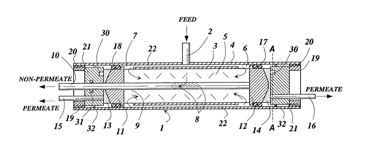
Fig. 1 shows a sectional view of an
embodiment of a double ended fluids separation
apparatus 1 of this invention, which comprises the
pressure shell 4, hollow fiber membrane bundle 5,
center core tube 9, impermeable barrier 3 and
15 tubesheets 11 and 12. The figure also shows first
port 2, second port 10, third port 15 and fourth port
16. Also shown are holes 8 in center core tube 9,
the uncovered entrance regions 6 and 7 of hollow
fiber membrane bundle 5, hollow fiber bore openings
20 13 and 19, e.g. in the form of slots or notches, in
the tubesheet, O-rings 17 and 18, threaded ring 19,
threads 20, cylindrical plugs 21 and annular space 22.
In a typical embodiment of the use of the
equipment illustrated by FigO 1, the fluid feed
25 stream, ~or e~ample air, enters the double ended
fluids separation apparatus 1 via first port 2, which
can be positioned in the pressure shell 4 at a point
about midway between tubesheets 11 and 12. An
impermeable barrier (for example, a thin film such as
30 polyethylene or polyvinylidene chloride) 3 forces the
fluid feed stream to travel along the annular space
22 between the double ended fluid separation device's
D-16718
- 17 - 2~7~
pressure shell 4 and the impermeable barrier 3. The
fluid feed stream initially comes into contact with
the exterior surface of the hollow fibers membrane
bundle 5 at the entrance regions 6 and 7, said hollow
5 fiber membranes comprising, for e~ample, a composite
membrane of porous polysulfone hollow fibers having a
very thin coating layer of the sulfonated
polysulfone. The fluid feed stream flows along the
e~terior surface of the hollow fibers of the double
10 ended hollow fibers membrane bundle 5 and exits
through holes 8 of center core tube 9. Center core
tube 9 e~tends through tubesheet 11 allowing the
non-permeating fluid stream to leave the permeator at
non-permeate second port 10. Permeate fluid flows
15 through the bores of the hollow fibers countercurrent
to the feed (non-permeate) stream and e~its the
hollow fiber bores at hollow fiber bore openings 13
and 19, the hollow fibers being embedded in
tubesheets 11 and 12, and e~its the permeator at
20 third and fourth ports 15 and 16. O-rings 17 and 18
act as a fluid tight seal to separate the high and
low pressure sides of the permeator, in essence also
separating the fluid feed stream and non-permeate
stream from the permeate stream.
First port 2 need not necessarily be
positioned to introduce fluid feed at the center of
pressure shell 4 if annular space 22 is wide enough
to permit free flow without any build-up of pressure
in annular space 22; prefera~ly, however, first port
30 2 is essentially at the center.
When pressurized fluid feed is introduced on
the shell side of the hollow fiber bundle, the
D-16718
- 18 - 207~Q
pressure force acting against the backside of each
tubesheet 11 and 12 tends to deflect each tubesheet
if there is no balancing force on the front side. To
prevent potential deflection of the tubesheets, a
5 physical support in contact with the front side of
each tubesheet is employed. In Fig. 1, threaded ring
19 engages permeator pressure shell 4 by threads 20
(as described in U.S. Patent No. 4,709,831) to retain
cylindrical plugs 21 and counterbalance the pressure
10 force.
The entrance and exits of the fluid streams
may be reversed. For example, fluid feed stream can
be charged into port 10 with non-permeate stream
exiting at port 2, permeate streams e~iting at ports
15 15 and 16 as shown in Fig. 2.
Figs. 3 and 4 show alternate constructions
of the double ended hollow fibers fluids separation
apparatus of this invention in which holes 8 in the
center core tube 9 and entrance regions 6 and 7 are
20 located in the similar positions shown in Figs. 1 and
2.
In the assembly shown in Fig. 3 the hollow
fiber membrane bundle 5 is mounted in the pressure
shell by means different than shown in Fig. 1. In
25 Fig. 3 there is a permeate containment plate 24
retained by means of a gasket 25, bolts 26 and nuts
27. O-rings 28 and 32 form an impervious seal for
cylindrical plug 21 and O-rings 31 and 32 form an
impervious seal for end plug 29.
In the embodiment shown in Fig. 3 the
tubesheets 11, 12 on both ends of hollow fiber
membrane bundle 5 are shown cut flat and the hollow
D-16718
- 19 2~7~
fiber ends are exposed on the end faces 13, 14 of
tubesheets 11, 12. The end plug 29 supports
tubesheet 11 at its perimeter to allow permeate gases
to collect for recovery via third port 15.
In the assembly shown in Fig. 4 the hollow
fiber membrane bundle 5 has been modified by the
presence of a barrier 23 located at about the
mid-point of the bundle. Inclusion of barrier 23 can
be useful in decreasing shell side fluid mi~ing near
10 extraction holes B. The construction of barrier 23
in a hollow fiber bundle is known to those of
ordinary skill in the art and can be formed, for
e~ample, by deposition of a polymer at the desired
point during the winding. This polymer can be in the
15 form of a heated thermoset fluid polymer at a
temperature which does not have an adverse effect on
the hollow fiber structures or in the form of a
curable polymer composition that is subsequently
treated to solidify and form solid barrier 23, e.g.,
20 an epo~y resin.
In the embodiment shown in Fig. 5, the
hollow fiber bundle 5 is covered with impervious
barrier 3 e~cept for the narrow e~posed entrance
region 7 which is located midway between the two
25 tubesheets 11 and 12 and the holes 8 in the center
core pipe 9 are located adjacent to the two terminal
tubesheets 11 and lZ. The impervious barrier 3 can
be a thin plastic sheet such as polyethylene film or
a reinforced epoxy composite, the latter may be
30 preferential if high fluid flow rates through the
bundle generate a significant pressure drop. The
fluid flows into the entrance port 10, travels along
D-16718
- 20 - 20~95~
the length of the center core tube 9, and flows into
the fiber membrane bundle matri~ 5 via holes 8. The
resistance to flow along the center core tube 9
should be small enough so that the flow of the fluid
5 into the hollow fiber membrane bundle 5 is equally
distributed through the two sets of holes 8.
Permeate fluid flows through the bores of the hollow
fibers and e~its the hollow fiber bores at hollow
fiber bore openings 13 and 14 and then e~its the
10 permeator through ports 15 and 16. Fluid which has
not permeated the fiber exits the fiber bundle
through bundle exit region 7 and then through
non-permeate port 2. The flow pattern indicated in
Fig. 5 is countercurrent with respect to the permeate
15 flow relative to the non-permeate flow. However, the
entrance and exit of the feed fluid and non-permeate
fluid streams may be reversed to provide for
cocurrent flow arrangement.
The double ended hollow fiber fluids
20 separation bundle and the permeator apparatus of this
invention are used ~or separating and enriching a
first component from a fluids mi~ture thereof with at
least one other component of said mi~ture or
dehydrating mi~tures of two or more liquid or gaseous
25 mi~tures. Typical multicomponent fluids mi~tures
that can be separated with the bundles and apparatus
of this invention one can mention He/N2, air,
C02/CH4, He/CH4~ 2/N2~ H2/C02~C/N2~ CH4/C2/H2S~
CO/H2, H2/CH4, He/CH4/N2, He/2/N2 ~ N2/H2, N2/CH4,
30 H2O/O2/N2; also included are many other compositions
known to those skilled in the art as being capable of
being separated by membrane permeation techniques.
D-16713