Note: Descriptions are shown in the official language in which they were submitted.
Z~ 8
SPECIFICATION
JOSEPH W. MUMMAW
METHOD AND APPARATUS FOR PURIFYING AND DISPENSING WATER
BACKGROUND OF THE INVENTION
1. Field of the Invention
The present invention relates generally to a method and
apparatus for purifying and dispensing water, and more particularly
to a portable system for making purified drinking water from
municipally treated water, and thereafter dispensing the drinking
water.
2. Description of Related Art
The bottled drinking water industry is a worldwide
multi-billion dollar industry. Health conscious consumers are
purchasing bottled drinking water in record numbers and that trend
is expected to continue.
Typically, bottled drinking water is sold in grocery stores.
Virtually all such bottled water is supplied to grocery stores by
remotely located bottle water manufacturers, thereby requiring
transportation of the bottled water from the remote location to a
particular grocery store location. Obviously, such transportation
entails undesirable costs and requires the grocery stores to
maintain storage space for inventory.
2~ J~
Purchasing bottled water from bottle water manufacturers is
disadvantageous for grocers for a number of reasons. One
disadvantage is that grocers must estimate the amount of bottled
water required for their periodic needs and order accordingly.
S Underestimating results in out-of-stock situations and
overestimating results in excess inventory. Another disadvantage
is that the grocery store must bear the often substantial cost of
shipping the bottled water from the bottled water manufacturer's
location to the its location. Once delivered, the bottled water
must then occupy valuable retail shelf space and/or warehouse
space. A further disadvantage is the problem of disposing of
unpurchased bottled water.
The present invention relates to on-site manufacture of
bottled drinking water for grocery stores. The invention
comprehends both purification and dispensation technology.
Applicant is aware of the following U.S. Patents relating
generally to water purification systems or dispensation systems:
Patent No. Issued Inventor Title
563,464 07-07-1896 Fahrney BOTTLE FILLER
963,342 07-05-1910 Warters DISPENSING APPARATUS
2,757,846 08-07-1956 Varrin LIQUID DISPENSERS
3,347,325 10-17-1967 Espenschied AUTOMATIC CONTAINER
FILLERS FOR DENTAL
UNITS AND THE LIKE
3,456,107 07-15-1969 Robertson WATER STERILIZATION
APPARATUS
3,580,304 05-25-1971 Chermack GLASS FILLER
3,330,782 12-29-1897 Veloz WATER STERILIZER
APPARATUS
4,230,571 10-28-1980 Dadd OZONE/ULTRAVIOLET
WATER PURIFICATION
4,780,200 10-25-1988 Bond WATER PURIFICATION
APPARATUS
4,867,052 09-19-1989 Cipelletti STERILIZING DEVICE
FOR AN ICE-CREAM OR
SIMILAR DELIVERING
MACHINE
"? ~ .r S ~
4,g09,931 03-20 1990 Bibi WATER-PU RI FI ER
DEVICE
4,968,437 11-06-1990 Noll FLUID PURIFICATION
SYSTEM
Fahrney relates to means for holding open a valve between a
bottle and a supply until the level of liquid in the bottle has
reached a predetermined point and then closing such valve or
permitting it to close.
Warters relates to an apparatus used in mixing and dispensing
effervescing beverages.
Varrin relates to dispensers of carbonated, gaseous or charged
liquids.
Espenschied relates to automatic container fillers for dental
units which are automatically actuated through the placing of a
container thereon.
Robertson relates to ultra-violet ray water purification
devices and in particular to a lamp cleaning device and tube
sealing apparatus.
Chermack relates to a glass filler for filling a plurality of
glasses on a tray at one time in response to the movement of the
glass tray into position on the filling fixture.
Veloz relates to a water purification apparatus for
sterilizing two streams of water from a single source of
ultraviolet light, whereby in a system using a reverse osmosis
unit, bacteria in water entering and leaving the unit are
destroyed.
Dadd relates to a method and apparatus for the purification of
water utilizing ultraviolet radiation and ozone in combination to
2~t~ 8
inactivate bacteria and certain viruses and to oxidize certain
undesirable compounds in the water.
Bond et al. relates to a water purification apparatus which
includes a tube allowing purified liquid which is not dispensed to
flow back into a main housing whereby the purified liquid is
recirculated to prevent contamination.
Cipelletti relates to a device for hygienically maintaining a
food mixture in the storage compartment and/or delivery area of an
ice-cream or similar delivering machine.
Bibi relates to a water purifier device for providing drinking
water, without ozonizing the water, for home or other use.
Noll et al. relates to a fluid purification system
incorporating fluid exposure to both ultraviolet radiation and
filtration.
None of the related art discloses the structure, operation,
and result of the present invented method and apparatus for
purifying and dispensing water.
SUMMARY OF T~E INVENTION
The present invention is a method and apparatus for purifying
and dispensing water which variously includes filtration,
ultraviolet radiation, and ozonation technology. Water, typically
municipally treated drinking water, is supplied from a water source
into a water inlet port through a water conduit and out of at least
one water outlet port. The invented method includes purifying the
water during transit through the water conduit and dispensing the
water. Purifying the water includes filtering the water through a
set of filters, radiating the water with ultraviolet light (in a
first embodiment), and ozonizing the water. Although the word
X~ ,.'8
"water" is used herein to refer to the fluid being processed
through the system, the term is also intended to encompass any
fluid created by insertirlg additives to water to create a drink.
Dispensing the water includes manually dispensing the water into a
container, automatically dispensing the ~ater into a container, or
spraying the water. First and second embodiments of the apparatus
include a water purification mechanism and a water dispensation
mechanism. The purification mechanism includes a set of filters,
an ultraviolet radiation device (in the first embodiment)l and an
ozoni~er. The dispensation mechanism of the first embodiment of
the apparatus includes a manual dispenser and a sprayer~ The
dispensation mechanism of the second embodiment of the apparatus
includes an automatic dispenser. In both embodiments, the
apparatus is contained within a portable housing.
OBJECTS OF THE INVENTION
A primary object of the present invention is to provide a
method and apparatus for bottling drinking water within a grocery
store or other establishment which can be employed by grocery store
personnel.
Another object of the invention is to provide a method and
apparatus for removing chlorine, taste, color, odor, heavy metals,
and bacteria from drinking water.
Another object of the invention is to provide a method and
apparatus for bottling drinking water within a grocery store or
other establishment which can be employed by grocery store
customers.
A further object of the invention is to provide a method and
apparatus for producing purified water for use in spraying grocery
produce.
7~
Another object of the invention is to provide a method and
apparatus for bottling drinking water which will significantly
reduce the amount linear footage normally required of a grocery
store to stock bottled drinking water, both on the store's retail
floor and on its warehouse floor.
It is also an object of the invention is to provide a method
and apparatus for bottling drinking water which will obviate "shelf
life" problems associated with existing bottled water products.
Another object of the invention is to provide a method and
apparatus for bottling drinking water on an "as needed" basis.
DESCRIPTION OF THE DRAWINGS
The foregoing and other objects will become more readily
apparent by referring to the following detailed description and the
appended drawings, in which:
Figure 1 is a front view of a first embodiment of the invented
apparatus for purifying and dispensing water showing a dispensing
compartment within a housing.
Figure 2 is a left side view of the invented apparatus shown
in Figure 1, showing a power outlet.
Figure 3 is a right side view of the invented apparatus shown
in Figure 1, showing a service manifold and sprayer attachment
connected thereto.
Figure ~ is a rear view of the invented apparatus shown in
Figure 1, showing interior components.
2~ f ~_J ~
Figure 5 is a detailed isometric view of the interior
components of the first embodi~ent of the invented apparatus.
Figure 6 is a front view of a second embodiment of the
invented apparatus for purifying and dispensing water showing a
dispensing compartment wi.thin a housing.
Figure 7 is a left side view of the invented apparatus shown
in Figure 6, the left side panel being removed to expose the
interior of the housing.
Figure 8 is a right side view of the invented apparatus shown
in Figure 6, the right side panel being removed to expose the
interior of the housing.
Figure 9 is a rear view of the invented apparatus shown in
Figure 6, the rear panel being removed to expose the interior of
the housing.
Figure 10 is an isometric view of the invented apparatus shown
in Figure 6.
Figure 11 is an isometric view of the interior components of
the second embodiment of the invented apparatus.
Figure 12 is a cross sectional view of the holder shown in
Figure 11, illustrating the tube section and forked end of the
holder, and a sensing device situated within the tube section.
Figure 13 is a schematic diagram of the automatic dispenser of
the embodiment of Figure 6.
Figure 14 is a -flow chart illustrating the invented method of
purifying and dispensing water.
2~ J~
Figure 15 is a flow chart oE the steps associated with
automatically dispensing purified water.
DETAILED DESCRIPTION
Referring now to the drawings, and particularly Figure 1, a
first embodiment of the invented apparatus 12 for purifying and
dispensing water, which includes filtration, ultraviolet radiation,
and ozonation technology, is shown. As depicted in Figure 5,
water, typically municipally treated drinking water, is supplied
from a water source 14 into a water inlet port 16 through a water
conduit 18 and out of at least one water outlet port 20a, 20b.
The apparatus 12 includes means for purifying the water and
means for dispensing the water. In the first embodiment, purifying
means includes a set of filters, an ultraviolet radiation device
28, and an ozonizer 30. Dispensing means includes a manual
dispenser 32 or a sprayer 36. The apparatus 12 is contained within
a portable housing 38.
Figures 1 through 4 depict the housing 38, which includes a
body having a front 42, a rear 44, a top 46, a bottom 48, a first
side 50, and a second side 51. The rear 44 of the housing 38 is
open and is provided with a door 52 attached to one side of the
housing 38 with attaching means 54 such as hinges. The door 52 may
be provided with latching means 58 such as a positive catch
mechanism in order to secure the apparatus 12 against tampering.
The housing 38 and the door 52 are preferably made of stainless
steel to permit easy cleaning of the apparatus 12.
The bottom 48 of the housing 38 includes means for
transporting the housing from one place to another, such as casters
64, as shown in Figure 4, or wheels. Four diagonal swivel type
casters 64 with polyurethane tires 66 are preferably affixed to the
bottom 48 of the housing 38. It is advantageous for at least one
z~
of the casters 64, preferably two, to be provided with a brake 68.
Since the housing 38 is mobile, it is also advantageous for person
and property alike that a portion of the housing 38 (such as the
lowermost four corners of the housing) be provided with bumper pads
70.
Figure 3 depicts the second side 51 of the housing 38 which
includes a service manifold 72. The service manifold 72 includes
the water inlet port 16, an auxiliary water outlet port 20b, and a
drain outlet port 74. Each port is preferably comprised of a brass
connector fitting. The water inlet port 16 connects the water
source 14, typically a standard water faucet 76, via a supply line
78, such as a hose or tube. A double check valve 79 may be
connected to the water inlet port 16 in order to control water
flow. A flow control valve 147 is connected to the water conduit
18 between a solenoid valve 156 and the manual dispenser 32. Flow
csntrol valve 147 diverts water to the water outlet port 20a, which
connects to the manual dispenser 32, or to the water outlet port
20b, which connects to the sprayer 36, or simultaneously to both
water outlet ports.
As shown in Figure 1, the front 42 of the housing 38 defines
a dispensing compartment 84, preferably made of high impact molded
plastic or fiberglass, with means for supporting a shelf 88, such
as brackets 86 affixed to the sides of the dispensing compartment
84. The brackets 86 and shelf 88 are preferably made of stainless
steel. A dispenser 90, such as a faucet, is positioned within the
dispensing compartment 84 so that the dispenser 90 will dispense
water into a container 94, such as a bottle, upon activating the
dispenser 90, the container 94 being positioned on top of the shelf
88 underneath the dispenser 90. The dispenser 90 is connected to
water outlet port 20a. At the base of the dispensing compartment
84 there is provided means 98 for draining waste water. Draining
means 98 includes a drain inlet port 100 and a drain conduit 102.
The drain conduit 102 connects the drain inlet port 100 to the
Z~ f .'3~
drain outlet port 74. A drain pan 104 having an opening 106
therein corresponding to the location of the drain inlet port 100
may be placed within the dispensing compartment 84.
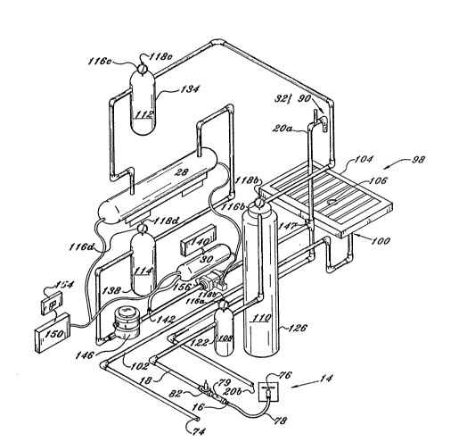
Purifying means contained within the housing 38 preferably
includes a set of filters, an ultraviolet radiation device 28, and
an ozonizer 30, as shown in Figure 5. The set of filters includes
a first filter 108, a second filter 110, a third filter 112, and a
fourth filter 114. Preferably, each filter has an associated
pressure gauge 116a, 116b, 116c, and 116d for monitoring water
pressure. Each pressure gauge 116 is integral with its associated
filter and is provided with a pressure release mechanism or safety
valve 118a, 118b, 118c, and 118d.
The first filter 108, preferably a 5 micron filter, is mounted
within the housing 38 and connects to the water conduit 18 between
the water inlet port 16 and the second filter 110. The first
filter 108 is a pre-stage filter for removing sludge, sand,
sediment, rust and undissolved particles from the water.
Preferably, solid particles having a diameter of greater than or
equal to 5 microns are removed from the water with the 5 micron
filter 108 housed in a first filter housing 122, such as a 20 inch
AMETEC filter housing, manufactured by Ametec, Inc. of Sheboygan,
Wisconsin.
The second filter llO, preferably a carbon filter, is mounted
within the housing 38 and connects to the water conduit 18 between
the first filter 108 and the third filter 112. Chemical and metal
contaminants, such as chlorine, herbicides, pesticides,
trihalomethanes, iron, lead, manganese, hydrogen sulfide, and
mercury, are removed from the water by passing the water through
the carbon filter 110. Preferably, the carbon filter 110 is a
granular activated filter within a 20 inch second filter housing
126.
2~7~7(~
The third filter 112, preferably a 1 micron filter, is mounted
within the housing 3~ and connects to the water conduit 18 between
the second filter 112 and the ultraviolet radiation device 28.
Preferably, the 1 micron filter 112, contained within a 20 inch
5third filter housing 134, is employed to remove from the water
solid particles having a diameter of greater than or equal to 1
micron and less than 5 microns.
The ultraviolet radiat on device 28 is mounted within the
housing 38 and connects to the water conduit 18 between the third
10filter 112 and the fourth filter 114. The preferred ultraviolet
radiation device 28 is a high performance ultraviolet output device
capable of removing approximately 99% of bacteria and viruses. An
example of such a unit is the Trojan 608 Plus, manufactured by
Trojan Technologies of London, Ontario, Canada.
15The fourth filter 114, preferably a .2 micron filter, is
mounted within the housing 38 and connects to the water conduit 18
between the ultraviolet radiation device 28 and a flow meter 146.
Particles, bacteria and viruses having a diameter of greater than
or equal to .2 microns and less than 1 micron are removed with the
20.2 micron filter 114, encased within a fourth filter housing 138,
such as a 20 inch AMETEC filter housing.
The ozonizer 30 is mounted within the housing 38 and connects
to a venturi valve 142 between the flow meter 146 and the solenoid
valve 156. The preferred ozonizer 30 is capable of providing up to
252.9 gr/m3 ozone to water using cold spark corona discharge, which
provides maximum sanitizing of the water. Such a unit is
manufactured by LMK Technolgies, of Monroe, North Carolina. The
preferred ozonizer 30 also communicates with an air filtration and
dryer mechanism 140.
30The filters employed with respect to the first embodiment of
the invented apparatus must be periodically replaced. The
frequency of replacement varies depending on usage. In general,
the estimated life of the 5 micron filter 108 is 6,000 gallons, the
estimated life of the l micron filter 112 is 18,000 gallons, the
estimated life of the .2 micron filter 114 is 37,500 gallons, and
the estimated life of the carbon filter 110 is 30,000 gallons. A
flow meter 146 is provided in order to measure the amount of water
processed through the apparatus 12. A pressure regulator 82
communicates with the water conduit 18 between the double check
valve 79 and the set of filters and provides constant pressure
within the system, and can be regulated to accommodate an auxiliary
connection simultaneously with processing of drinking water (e.g.,
the sprayer 36). The preferred inlet pressure is 100 psi and the
preferred operating pressure is 40 psi.
The ultraviolet radiation device 28 and ozonizer 30 are
powered by a power source 150 which supplies power to the two units
via a power outlet 152. In the preferred embodiment, the power
source 150 is 120 Volt, 20 Amp, single phase circuit. An on/off
switch 154 is provided on the apparatus 12 for turning power on and
off. In addition, the ultraviolet radiation device 28 and the
ozonizer 30 are electrically connected to the solenoid valve 156
which automatically stops the flow cf water through the apparatus
12 in the event either the ultraviolet radiation device 28 or the
ozonizer 30 fail to operate.
The first embodiment of the apparatus 12 is primarily intended
for bottling purified water by grocery store personnel for
production purposes. In a second embodiment, shown in Figures 6
through lO, apparatus 12' is adapted for dispensing purified water
into containers to consumers or users of the apparatus 12' upon
demand. Water is supplied from a water source 14' into a water
inlet port 16' through a water conduit 18' and out of at least one
water c,utlet port 20', as shown in Figure 11.
- 12
2~
Apparatus 12' includes means for purifying the water and means
for dispensing the water. Purifying means includes a set of
filters and an ozonizer 30'. Dispensing means preferably includes
an automatic dispenser 34', illustrated in Figure 13. The
apparatus 12' is contained within a portable housing 38'.
Figure 6 depicts the housing 38', which includes a body having
a front 42', a rear 44', a top 46', a bottom 48', a first side 50',
and a second side 51'. The bottom 48' of the housing 38' includes
means for transporting the housing from one place to another, such
as casters 64'. A water inlet port 16' connects to water source
14', typically a standard water faucet 76', via a supply line 78',
such as a hose. A double check valve 79' may be connected to the
water inlet port 16' in order to control water flow. A pressure
regulator 82' communicates with the water conduit 18' between the
double check valve 79' and the set of filters and provides constant
pressure within the system. The preferred operating pressure is 20
to 24 psi.
The front 42' of the housing 38' defines a dispensing
compartment 84', preferably made of high impact molded plastic or
fiberglass. A dispenser 90' is positioned within the dispensing
compartment 84' so that the dispenser 90' will dispense water into
a container 94', such as a bottle, the container 94' being held in
place underneath the dispenser 90' by a holder 97'. The holder 97'
comprises a tube 97a' having a forked end 97b' for supporting the
neck of the container 94'. The dispenser 90' is connected to a
water outlet port 20'. At the base of the dispensing compartment
84' there is provided means 98' for collecting waste water, if any,
such as a drain pan 104'.
Purifying means is contained within the housing 38' and
preferably includes a set of filters and an ozonizer 30'. The set
of filters includes a first filter 108', a second filter 110', and
a third filter 112'. Preferably, the third filter has an
13
a
associated pressure gauge 116' for monitoring water pressure. The
remaining filters may also be provided with pressure gauges. The
pressure gauge 116' is integral with the third filter 112' and is
provided with a pressure release mechanism 118'.
The first filter 108', housed within a first filter housing
122', is mounted within housing 38' and conhects to the water
conduit 18' between the water inlet port 16' and the second filter
110'. The first filter 108' is a pre-stage filter for removing
particulate matter.
The second filter 110', housed within a second filter housing
126', is mounted within the housing 38' and connects to the water
conduit 18' between the first filter 108' and the third filter
112'. The preferred filter media is granular activated carbon,
which filters undesirable taste and odor from the water. The
filter 110' is capable of processing approximately 24,000 gallons
of water without replacement.
The third filter 112', housed within a third filter housing
134', is mounted within the housing 38' and connects to the water
conduit 18' between the second filter 110' and a flow meter 146'.
The flow meter 146' is provided in order to measure the amount of
water processed through the apparatus 12', and to provide measured
flow within the system. The third filter 112' preferably filters
particulate matter having a diameter of greater than or equal to 1
micron from the water and provides taste and odor filtration
through activated carbon.
The ozonizer 30' is mounted within the housing 38' and
connects to a venturi valve 142' between the flow meter 146' and a
solenoid valve 156'. The preferred ozonizer 30' is capable of
providing up to 2.9 gr/m3 ozone to water using cold spark corona
discharge. The preferred ozonizer 30' also communicates with an
air filtration and dryer mechanism 140'.
~ 3~
The ozonizer 30', flow meter 146', and a control device 158',
discussed hereafter, are powered by a power source 150' which
supplies power to those units. An on/off switch 154' is provided
on the apparatus 12' for turning power on and off. In addition,
the ozonizer 30' communicates with the solenoid valve 156' through
the control device 158' which automatically shuts down the
apparatus 12' in the event the ozonizer 30' fails to operate.
As illustrated in Figure 13, a control device 158' monitors
and controls the operation of the apparatus 12'. As used herein,
the term "control device" means an electric or electronic device
(e.g., a computer) for governing in some programmable and
predetermined way the power delivered to an ancillary device. The
control device 158' is connected to, communicates with, and governs
the operation of the following peripheral devices: a first button
or switching means 160', a first sensor 162', a second sensor 164',
means for generating a visual message, means for generating an
aural message, a second button or switching means 166', the
ozonizer 30', the solenoid valve 156', and the flow meter 146'.
The control device 158' includes means 158a' for processing
information, such as an Intel 8080 microprocessor (manufactured by
Intel Corporation of Santa Clara, California), means 158b' for
storing information, such as a random access memory (RAM) or read
only memory (ROM), and means 158c' for communicating information
between the processing means and the storing means, such as a bus.
Means 158d' for input and output between the control device and the
periph~ral devices is also included.
The first button 160' and the control device 158' are
connected such that depressing the first button 160' signals the
control device 158' to enter an instruction mode, discussed
hereafter. The first sensor 162' is preferably a magnetic door
sensor which detects whether a dispenser door 168' is open or
closed, and which signals the door status to the control device
158'. The second sensor 164' is preferably an optical photo
2 ~
sensor, such as a Warner Model MCS 653-13 (manufactured by Warner
Electric, Inc. of Marengo, Illinois), positioned within the holder
97' and connected to the control device 158', for signalling the
presence or absence of a container 94' in the holder 97' to the
5 control device 158'. Visual message means include a set of light
emitting diodes (LEDs), 170a', 170b', 170c', 170d', 170e', 170f',
positioned on the front 42' the apparatus, which are connected to
the control device 158'. Each LED 170' is associated with a
textural message 171' appearing adjacent to the LED. Of course,
other visual message means may also be employed, such as a video
monitor device. Aural message means include a speaker 172' mounted
on the front 42' of the apparatus, which is connected to the
control device 158', and stored messages which are generated
through the speaker 172' in spoken form by a voice generator 174'
under the control o the control device 158'. Preferably, the
messages are encoded and digitally stored in the storing means
158b' of the control device 158' and may be varied by reprogramming
of the control device 158'. However, the control device 158' could
also interface with a tape player/recorder or similar device to
accomplish a similar result. The second button 166' connects to
the control device 158' and signals the control device 158' to
commence filling the container 94' with water. The control device
158' regulates the amount of water dispensed in accordance with
signals generated by flow meter 146'. Depressing the second button
166' results in a continuous filling of the container 94' for a
predete~mined time period.
Figure 14 illustrates the invented method, which includes
purifying the water during transit through the water conduit, step
200, and thereafter dispensing the water, step 202. Purifying the
water includes filtering the water through a set of filters,
radiating the water with ultraviolet light (in the first
embodiment), step 206, and ozonizing the water, step 208.
Dispensing the water includes manually dispensing the water into a
16
2~
container, step 210, automatically dispensing the water into a
container, step 212, or spraying the water, step 214.
Water is supplied from the water source into the water inlet
port, step 216. As used herein, the term "heavy water" means water
containing dissolved iron or manganese. If the water is not heavy
water, condition 228, solid particles having a diameter of greater
than or equal to approximately 5 microns are filtered from the
water, step 218. If the water is heavy water, d.issolved metals
tferrous matter) are removed from the water with a metals filter,
step 230, and the process continues with step 220. Chemical and
metal contaminants, such as chlorine, herbicides, pesticides,
trihalomethanes, iron, lead, manganese, hydrogen sulfide, and
mercury, are then removed from the water by filtering the water
through a carbon media bed, step 220. Solid particles having a
diameter of greater than or equal to 1 micron and less than 5
microns are then filtered from the water, step 222. In one
embodiment of the process (condition 226 is "Yes"~, bacteria and
viruses are thereafter removed from the water by radiating the
water with ultraviolet light, step 206, and particles, bacteria and
viruses having a diameter of greater than or equal to .2 microns
and less than 1 micron are filtered from the water, step 224. In
another embodiment of the process (condition 226 is "No"), the
process continues with step 208. Ozone is introduced into the
water to provide ma~imum sanitizing of the water, step 208. Upon
completion of the purification process, the purified water is
manually dispensed into a container, step 210, automatically
dispensed into a container, step 212, or sprayed, step 214.
The process step for automatically dispensing water into the
container 94', step 212, includes providing the container 94' in
which to dispense the water; instructing a user of the apparatus
12' to place the container 94' in the holder 97' beneath the
dispenser 90'; automatically sensing the presence of the container
94' in the holder 97' and automatically instructing the user of the
~r~f~.7~
apparatus 12' to start the dispensing process; automatically
dispensing an appropriate amount of water; and advising the user
upon completion of the process to place a cap on the container 94'
and to remove the container 94' from the holder 97'.
As shown in Figure 15, automatically dispensing the water
includes a start state 250. Start state 250 includes three modes:
operation mode; instruction mode; and heuristic mode. The default
mode is the operation mode which facilitates dispensing of water
into the container 94'. Upon enabling the apparatus 12' by turning
the on/off switch 154' on, the control device 158' monitors the
status of the first sensor 162' and a determination 252 is made as
to whether the dispenser door 168' is open. If the first sensor
162' indicates that the door 168' is open, then first visual and
aural messages are conveyed to the user to prepare and load a
container 94' to be filled with water, step 254. The first visual
message comprises enabling the first LED 17Oa'. In addition, the
voice generator 174' issues an appropriate aural message through
the speaker 172'. If the door 168' is closed, the first sensor
162' is repeatedly tested until the door 168' is opened, step 292.
After conveying the first messages to the user, a determination 256
is made using the second sensor 164' as to whether the container
94' has been appropriately loaded into place. If so, the first
visual message is removed (i.e., the LED is turned off) and second
visual and aural messages are conveyed to the user to close the
dispenser door 168', step 258. The first sensor 162' is then used
to determine whether the door 168' has been closed in response to
the ;econd messages. If the door 168' has been closed, then the
second visual message is removed and third visual and aural
messages instruct the user to press the second button 166', step
260. If the door 168' has not been closed, then the first sensor
162' is tested until the door 168' is closed. Upon pressing the
second button 166', a determination 264 is made as to whether the
ozonizer 30' is operational. If the ozonizer 30' is not
operational, step 264, the apparatus 12' is taken out of service
18
and sixth visual and aural messages so inform the user, step 294.
The sixtll visual message preferably involves the control device
158' enabling the sixth LED 170f'. If the ozonizer 30' is
operational, the ozoni~er 30' is started and the solenoid valve
156' Gpened.
In the operation mode, the timer 158e' is then started, step
282, and a message is communicated to the user, step 284.
Typically, the message is a commercial message. Once the time
period defined by the timer 158e' has expired, the solenoid valve
156' is closed, the ozonizer 30' is stopped, and the third visual
message is removed. Fourth visual and aural messages then instruct
the user to cap the container 94' before removing the container 94'
from the apparatus 12', step 288. If the second sensor 164'
indicates that the container 94' has been removed, then the fourth
visual message is removed and fifth visual and aural messages are
issued thanking the user, step 290. The apparatus 12' is then
reset to the start state 250 in preparation for another container
filling cycle. At certain test points in the process (viz., 252,
256, and 262), a determination 292 is made concerning whether the
test has been performed for longer than a predetermined timeout
period. If so, the apparatus 12' is reset. If not, the test is
performed again.
As a preferred alternative to the above described sequence,
the first, second, and third aural messages may instead be
generated upon pressing the first button 160'. Upon receiving a
signal from the first button 160', the control device 158' enters
intG an instruction mode. In the instruction mode, the first,
second, and third aural messages are heard by the user only upon
the user's request, by pressing the first button 160' at the
beginning of the process, 250, and are not heard during process
steps 254, 258, and 260, respectively.
19
r~ ~J 8
Another aspect of the automatic dispenser 34' is a heuristic
mode which permits the dispenser 3~' to be "taught" what amount of
water to be dispensed into the container 94'. The control device
158' includes a heuristic mode switch 158f' which, upon being
enabled, places the apparatus 12' in heuristic mode. Control
device 158' facilitates performance of the same sequence of steps
normally associated with the operation mode, with a few important
exceptions. If the heuristic mode switch has been enabled, then
the process flow follows the "Yes" path at step 270, namely,
monitoring the flow of water via the flow meter 146'. The second
button 166' may be depressed and released one or more times thereby
signalling the control device 158' to start and stop the flow of
water. The flow meter 146' communicates to the control device 158'
information corresponding to the aggregate amount of water which
flowed through the flow meter in response to pressing the second
button 166'. Monitoring of the flow of water continues until the
second sensor 164' indicates that the container 94' has been
removed. Once the container 94' has been removed, storing means
158b' contains information which defines the volume of water
desired to be dispensed in the operation mode. That information is
then used in the operation mode by the timer 158e' to determine
when to cease filling the container 94'.
SUMMARY OF THE ACHIEVEMENTS
OF THE OBJECTS OF THE INVENTION
F~rom the foregoing, it is readily apparent that I have
invented an improved method and apparatus for bottling drinking
water within a grocery store or other establishment which can be
employed by grocery store personnel or customers, for removing
chlorine, taste, color, odor, heavy metals, and bacteria from
drinking water, for producing purified water for use in spraying
grocery produce, which will obviate "shelf life" problems
associated with existing bottled water products, and for bottling
drinking water on an "as needed" basis.
Z~.~' t ~
It is to be understood that the foregoing description and
specific embodiments are merely illustrative of the best mode of
the invention and the principles thereof, and that various
modifications and additions may be made to the apparatus and method
by those skilled in the art, without departing from the spirit and
scope of this invention, which is therefore understood to be
limited only by the scope of the appended claims.