Language selection

Search

Patent 2079695 Summary

Third-party information liability

Some of the information on this Web page has been provided by external sources. The Government of Canada is not responsible for the accuracy, reliability or currency of the information supplied by external sources. Users wishing to rely upon this information should consult directly with the source of the information. Content provided by external sources is not subject to official languages, privacy and accessibility requirements.

Claims and Abstract availability

Any discrepancies in the text and image of the Claims and Abstract are due to differing posting times. Text of the Claims and Abstract are posted:

  • At the time the application is open to public inspection;
  • At the time of issue of the patent (grant).
(12) Patent: (11) CA 2079695
(54) English Title: DEVICE FOR SEALING THE END OF A HEAT-SHRUNK SLEEVE
(54) French Title: DISPOSITIF SERVANT A SCELLER L'EXTREMITE D'UN MANCHON THERMO-RETRECI
Status: Deemed expired
Bibliographic Data
(51) International Patent Classification (IPC):
  • B25B 9/04 (2006.01)
  • B29C 61/06 (2006.01)
  • G02B 6/44 (2006.01)
  • H01R 4/72 (2006.01)
  • H02G 15/013 (2006.01)
  • H02G 15/18 (2006.01)
(72) Inventors :
  • SCHOTTKER, REINHARD (Germany)
  • GRAJEWSKI, FRANZ (Germany)
(73) Owners :
  • RAYCHEM N.V. (Belgium)
(71) Applicants :
(74) Agent: SMART & BIGGAR
(74) Associate agent:
(45) Issued: 1999-03-02
(22) Filed Date: 1992-10-02
(41) Open to Public Inspection: 1993-04-05
Examination requested: 1996-03-13
Availability of licence: N/A
(25) Language of filing: English

Patent Cooperation Treaty (PCT): No

(30) Application Priority Data:
Application No. Country/Territory Date
P 41 32 961.9 Germany 1991-10-04

Abstracts

English Abstract


A device for sealing the lend of a heat-shrunk
sleeve surrounding a branching connection of electrical
or optical cables grips the outer surface of the sleeve
between the branching cables and keeps the opposing
surfaces of the sleeve in contact with each other between
the cables, during cooling after the heat-shrinking of
the sleeve. The device has two parallel arms which are
interlocked with each other at one end. The distance
between the arms can be changed in such a way, that the
arms remain essentially parallel at any distance from
each other. The device is preferably installed after
heat-shrinking.


French Abstract

Cette invention concerne un dispositif de scellement de l'extrémité d'un manchon thermorétrécissable protégeant une connexion de câbles électriques ou optiques. Ce dispositif qui prend appui sur la surface extérieur du manchon serre celui-ci entre les câbles raccordés et maintient ses surfaces opposées en contact entre lesdits câbles pendant le refroidissement du manchon thermorétréci. Il comporte deux bras parallèles interconnectés par un bout. L'espacement des bras peut être modifié tout en conservant essentiellement le parallélisme de départ à toutes les distances de séparation. Le dispositif se met en place de préférence après le thermorétrécissement du manchon.

Claims

Note: Claims are shown in the official language in which they were submitted.


THE EMBODIMENTS OF THE INVENTION IN WHICH AN EXCLUSIVE
PROPERTY OR PRIVILEGE IS CLAIMED ARE DEFINED AS FOLLOWS:

1. A device for sealing a heat-shrunk sleeve
surrounding branching cables comprising:

first and second parts having two parallel arms
which grip the sleeve between the branching cables and
keep opposing surfaces of the sleeve in contact with each
other between the cables during cooling after
heat-shrinking of the sleeve, each of the first and second
parts having one of said two parallel arms, a head
portion located at the end of its respective arm and a
connector protruding from the head portion, the connector
of the first part having two beams forming a gap
therebetween, the connector of the second part having a
single beam located in the gap, the beam of the second
part having catch elements at a free end thereof
interlocked with catch elements in a recess in the first
part so that the distance between the arms can be changed
with the arms remaining generally parallel to each other
at any distance between them, wherein recesses are
provided on both sides of the beam in the head portion of
the second part and ends of the beams of the first part
are located in the recesses of the second part.

2. A device according to claim 1, wherein the
recess of the first part is between its two beams and the
end of the beam of the second part is located in the
recess of the first part.

3. A device according to claim 1, wherein the
free end of the beam of the second part has a slot.

4. A device according to claim 1, wherein each of
the connectors extends normally to its respective arm.


5. A device for sealing a heat-shrunk sleeve
surrounding branching cables comprising:
first and second parts having two parallel arms
which grip the sleeve between the branching cables and
keep opposing surfaces of the sleeve in contact with each
other between the cables during cooling after
heat-shrinking of the sleeve, each of the first and second
parts having one of said two parallel arms, the first
part having two beams forming a gap therebetween, the
second part having a single beam located in the gap, the
beam of the second part having catch elements at a free
end thereof to provide means for interlocking with catch
elements in a recess in the first part so that the
distance between the arms can be changed with the arms
remaining generally parallel to each other at any
distance between them.

6. A device according to claim 5, wherein the
catch elements in the recess of the first part are
gripped by the catch elements located on the free end of
the beam of the second part.

7. A device according to claim 6, wherein the free
end of the beam of the second part has a slot.

8. A device according to claim 5, wherein the free
end of the beam of the second part has a slot.

9. A device according to claim 5, wherein
recesses are provided on both sides of the beam in the
head portion of the second part and ends of the beams of
the first part are located in the recesses of the second
part.


10. A device according to claim 9, wherein the
recess of the first part is between its two beams and the
end of the beam of the second part is located in the
recess of the first part.

11. A device according to claim 10, wherein the
catch elements in the recess of the first part are
gripped by the catch elements located on the free end of
the beam of the second part.

12. A device according to claim 11, wherein the
free end of the beam of the second part has a slot.

13. A device according to claim 5, wherein the
recess of the first part is between its two beams and the
end of the beam of the second part is located in the
recess of the first part.

14. A device according to claim 13, wherein the
catch elements in the recess of the first part are
gripped by the catch elements located on the free end of
the beam of the second part.

15. A device according to claim 14, wherein the
free end of the beam of the second part has a slot.


Description

Note: Descriptions are shown in the official language in which they were submitted.


207Y69~

DEVICE FOR SEALING THE END OF A HEAT-SHRUNR SLEEVE

BACKGROUND OF THE INVENTION


Technical Field

The invention concerns a device for sealing a heat-
shrunk sleeve and, more particularly, for sealing the end
of a heat-shrunk sleeve surrounding a branch connection
of electrical or optical cables.

Description of the Prior Art

A 1968 pamphlet by the Raychem Company entitled
"Thermofit Tubing Splice Encapsulation Directions"
introduces a technique, whereby two cables are inserted
into one end of a heat-shrinkable sleeve. The inside
surface of the heat-shrinkable sleeve is coated with hot-
melt adhesive. While the sleeve is hot, the area of the
sleeve between the two cables is held together with a
pliers-type tool. The hot-melt adhesive liquefies during
shrinking, and is pressed into the empty spaces by the
shrinking sleeve. Excess hot-melt adhesive emerges from
the end of the sleeve. The tool can be removed after the
branch arrangement cools. The cooled hot-melt adhesive
keeps the opposing areas between the cables together and
seals the inlet area. The shape of the pliers-type tool
is disclosed as needle-nosed.
Instead of the pliers-type tool, it is known from
U.S. Patent No. 4,298,415 to insert a clamp from the end
of the sleeve to the inlet area of the sleeve between the
cables. A clamp with three legs is used in a preferred
configuration, where one of the legs is placed inside the
sleeve and the other two are located outside of the
sleeve. The leg on the inside of the sleeve is coated
with hot-melt adhesive. During heat-shrinking, the heat
is transferred by the metal clamp to the inside of the
sleeve, where it liquefies the hot-melt adhesive. This

- 207~695


the metal clamp to the inside of the sleeve, where it
liquefies the hot-melt adhesive. This technique has been
used in the production of communications cable sleeves.
Installing this known clamp becomes especially difficult
~hen the end of the sleeve is not readily accessible.
Furthermore, the installer needs both hands, because the
clamp installation requires squeezing the inlet area
together. Certain precautions must be taken to prevent the
clamp from coming off during heat-shrinking of the sleeve,
which increases the manufacturing costs of the clamp. Thus,
it is known to provide the clamp with a saw tooth profile
and to manufacture the clamp from a heat-releasing metal
alloy.

SUMMARY OF THE INVENTION

An object of the present invention is to improve the
prior art devices, to permit installation of the device
a~ter heat-shrinking, and to prevent the device from coming
off the sleeve during the heat-shrinking process.

The device of the present invention is attached to the
outer surface of the sleeve between the branching cables,
and keeps opposing surface areas of the sleeve in contact
with each other between the ca~les during cooling, after
they were heated to shrink the sleeve. The device has two
parallel arms that are interlocked with each other to form a
closure at one end.

The distance between the arms can be changed, so that
the arms remain essentially parallel at any distance from
each other.


:. .: , : ~ , :

~79~9~


The device according to the invention can be attached
to the end of the sleeve after heat-shrinking. The arms of
the device can subsequently be brought closer to each other,
which causes the opposing areas of the sleeve to make
contact with each other. The st:ill liquid hot-melt adhesive
is pressed by the force of the arms to fill any remaining
empty spaces. Excess adhesive emerges from the end of the
sleeve.

However, it is also possible to attach the device to
the area of the sleeve in q~lestion before heat-shrinking.
Here as well, the distance between the arms is reduced after
the attachment, until both arms touch the outside of the
sleeve. The opposing areas are held together during heat-
shrinking, and any excess liquid hot-melt adhesive emerges
from the end of the sleeve.

The device o~ the present invention is composed of
first and second parts. The parts can be assembled at the
factory or at the installation site. Both the first and
second partS have an arm, a head portion at the end Of the
arm and a connector protruding from the head portion.
Preferably, the connectors extend perpendicular to the arms.
The parts of the device are assembled by means of the
connectors, which positively lock to each other. The
positive lock connection of the parts is achieved with the
use of catch elements.

The connector of the first part has two beams forming
a gap between them, while the connector of the second part
has a beam inside the gap. Recesses are provided in the
head portion of the second part on both sides of its beam

2~79~5


and the beam ends of the ~irst part extend into the
recesses.

The head portion of the f:irst part has a corresponding
recess, in which the beam end of the second part is located.
The recesses in the first and second parts guide the parts
during assembly.

The recess of the first part has catch elements, Which
grip corresponding catch elements on the outside of the beam
o~ the second part. The catch elements set the distance
between the arms of the first and second parts. There is a
sufficient number of catch elements, so that several
distances can be set. The beam of the second part has a
slot extending longitudinally its free end adjacent the
catch elements. This permits the end of the beam to be
slightly squeezed when inserted in the recess of the first
part. When the catch elements of the first and second parts
engage, it is no longer possible to easily separate the
parts.

BRIEF DESCRIPTION OF THE DRAWINGS
The invention will be explained in more detail by
means of the following drawings:
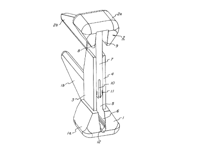
Figures 1 and 2 show perspective views of the
device in the open position (Figure 1) and in the closed
position (Figure 2).

DETAILED DESCRIPTION OF THE INVENTION

The device of the present invention for sealing the
end of a heat-shrunk sleeve comprises a first part 1 and a


2079~95


second part 2. Each of the parts 1 and 2 has a head portion
la or 2a, and an arm lb or 2b. The arms lb and 2b are
generally parallel to each other in any position. Both
parts 1 and 2 have connectors, by means of which parts 1 and
S 2 can be assembled to form the device of the invention. The
connector of the first part 1 has two beams 3 and 4, which
form a gap 5 between themselves. The gap 5 extends to a
recess 6 in the head portion la.

The connector of the second part 2 has a beam 7, which
extends from the head portion 2a. Both sides of the base of
beam 7 are provided with recesses 8 and 9 in the head
portion 2a, whose width is of a size that permits the free
ends of beams 3 and 4 to be inserted. The free end of beam
7 has a slot lo and catch elements 11, which, in the
assembled condition, combine with catch elements 12 located
in recess 6.

The surface of head portions la and 2a has a rounded
contour, so that parts 1 and 2 fit well into the hand of the
user during installation and sealing of the sleeve end. The
opposing surfaces of arms lb and 2b are also rounded, or
have a triangular cross section.

Parts 1 and 2 are preferably manufactured by in~ection
molding a heat resistant plastic resin material, e.g.
polyamide, polycarbonate, polyester or by compression
molding a synthetic resin. Parts 1 and 2 may be
preassembled at the factory to have the assembled
relationship shown in Figure 1, but the catch elements 11
and 12 must be prevented from interacting. To prevent
interaction of the preassembled parts, a formed part (not
shown), e.g. of corrugated cardboard or polystyrene, can be


~ . ,


.
!' - . : ~ '

2079~9~
.


placed in gap 5 or in recess 6. Alternatively, parts 1 and
2 may be assembled for the first time at the installation
site.

Figure 2 shows the device in the assembled, i.e.
operative, condition. The arms lb and 2b are loGated on the
outside surface of a heat-shrunk sleeve (not shown) between
the branching cables (not shown). Parts 1 and 2 are
interlocked by means of catch elements 11 and 12 to hold the
parts in assembly.

Thus, it can be seen from the foregoing specification
and attached drawings that the present invention provides an
effective means for establishing intimate contact of the
heat shrinkable material in the area between two closely
adjacent members during a heat sealing operation.

The preferred embodiment admirably achieves the
objects of the present invention; however, it should be
2~ appreciated that departures can be made by those skilled in
the art without departing from the spirit and scope of the
invention which is limited only by the following claims.

Representative Drawing
A single figure which represents the drawing illustrating the invention.
Administrative Status

For a clearer understanding of the status of the application/patent presented on this page, the site Disclaimer , as well as the definitions for Patent , Administrative Status , Maintenance Fee  and Payment History  should be consulted.

Administrative Status

Title Date
Forecasted Issue Date 1999-03-02
(22) Filed 1992-10-02
(41) Open to Public Inspection 1993-04-05
Examination Requested 1996-03-13
(45) Issued 1999-03-02
Deemed Expired 2005-10-03

Abandonment History

There is no abandonment history.

Payment History

Fee Type Anniversary Year Due Date Amount Paid Paid Date
Application Fee $0.00 1992-10-02
Registration of a document - section 124 $0.00 1993-04-20
Maintenance Fee - Application - New Act 2 1994-10-03 $100.00 1994-09-02
Maintenance Fee - Application - New Act 3 1995-10-02 $100.00 1995-09-05
Maintenance Fee - Application - New Act 4 1996-10-02 $100.00 1996-09-03
Maintenance Fee - Application - New Act 5 1997-10-02 $150.00 1997-09-22
Maintenance Fee - Application - New Act 6 1998-10-02 $150.00 1998-10-02
Final Fee $300.00 1998-11-16
Maintenance Fee - Patent - New Act 7 1999-10-04 $150.00 1999-09-13
Registration of a document - section 124 $50.00 2000-04-26
Maintenance Fee - Patent - New Act 8 2000-10-02 $150.00 2000-09-15
Maintenance Fee - Patent - New Act 9 2001-10-02 $150.00 2001-09-18
Maintenance Fee - Patent - New Act 10 2002-10-02 $200.00 2002-09-18
Maintenance Fee - Patent - New Act 11 2003-10-02 $200.00 2003-09-17
Owners on Record

Note: Records showing the ownership history in alphabetical order.

Current Owners on Record
RAYCHEM N.V.
Past Owners on Record
GRAJEWSKI, FRANZ
KABELMETAL ELECTRO GMBH
SCHOTTKER, REINHARD
Past Owners that do not appear in the "Owners on Record" listing will appear in other documentation within the application.
Documents

To view selected files, please enter reCAPTCHA code :


To view images, click a link in the Document Description column. To download the documents, select one or more checkboxes in the first column and then click the "Download Selected in PDF format (Zip Archive)" or the "Download Selected as Single PDF" button.

List of published and non-published patent-specific documents on the CPD .

If you have any difficulty accessing content, you can call the Client Service Centre at 1-866-997-1936 or send them an e-mail at CIPO Client Service Centre.


Document
Description 
Date
(yyyy-mm-dd) 
Number of pages   Size of Image (KB) 
Cover Page 1994-02-19 1 28
Abstract 1994-02-19 1 30
Claims 1994-02-19 3 112
Drawings 1994-02-19 2 45
Description 1994-02-19 6 263
Claims 1998-03-11 3 111
Drawings 1998-03-11 2 30
Cover Page 1999-02-23 1 45
Description 1998-03-11 6 256
Representative Drawing 1998-09-09 1 13
Representative Drawing 1999-02-23 1 7
Correspondence 1998-10-07 1 17
Correspondence 1998-11-16 1 38
Fees 1998-10-02 1 42
Assignment 2000-04-26 2 78
PCT Correspondence 1993-02-09 1 41
Office Letter 1993-01-08 1 37
Office Letter 1996-04-10 1 42
Prosecution Correspondence 1996-03-13 1 35
Prosecution Correspondence 1996-03-19 3 77
Prosecution Correspondence 1996-03-13 5 199
Fees 1996-09-03 1 35
Fees 1994-09-02 1 31
Fees 1995-09-05 1 34