Note: Descriptions are shown in the official language in which they were submitted.
2~7 ~'.3~
203-555 (1254)
APPARATUS FOR APPLYING SURGICAL FASTEN~RS
BAC~GROUND OF T~ INVBNTION
1. Field of th~ Inventio~
The present invention relates to surgical instruments
for applying surgical fasteners or staples to body tissue, and
more particularly to an apparatus for applying surgical fasteners
having adjustable me~chanisms for controlling the spacing between
the jaw members through which the tissue passes during the
fastening or stapling procedures.
2. Discu~sion of the Related Ar~
Surgical fastening devices having means for controlling
the spacing between the jaw members are well known in the art.
These devices typically include indicating means to provide a
reading of the spacing between the jaw members. Devices are also
known in the art which provide latching mechanisms to actuate the
firing mechanism only when the distance between the jaws is within
a preset range. These devices typically include a complex lock-out
mechanism.
Various closing mechanisms are provided in the prior art
for use with surgical fastening devices. The most notable of
these devices utilize a complex worm gear-type arrangement or
screw bearing member to open and close the spacing between the jaw
members of the surgical fastening apparatus. These devices
generally provide a rotatable knob or wing-like assembly at the
trigger end of the device remote from the jaw mechanism which
carries the fastener cartridge, and a screw-like mechanism is
provided that passes through the body of the device to translate
the rotational movement of the knob into longitudinal movement of
the cartridge frame to open and close the spacing between the
........ , ,, , ,,,, ,." . , . ,,.,. _ . ,. ,.. ,.. ,. ... ,.,~. ,.. ,... .,,,.. ,; .. . ;.. ,,, ~ ,. . ; .. ,
-2- 2~7~f'
jaws. As the jaw members are closed around a tissue site to which
fasteners are to be applied, the surgeon must grasp the device
with one hand while rotating the knob or wing-like assembly with
the other hand. As the jaws members close about the tissue to
pinch the tissue therebetween, the surgeon then ceases rotation
and activates the trigger mechanism the drive the fasteners into
the tissue. Several known devices provide a trigger-like
mechanism, while others provide a secondary rotatable knob for
driving the fasteners by rotational movement. Many devices
provide an indicator means near the rotatable knob which gives a
visual indication of the spacing between the jaw members prior to
firing.
These prior art devices are subject to several
disadvantages in both use and construction which render these
devices difficult to operate and expensive to manufacture. Many
of the devices are cumbersome in use in that the surgeon must
operate the device with both hands, holding the body of the
instrument in one hand while rotating the knob or wing assembly
with the other hand. This may lead to inaccurate stapling or
fastening since the surgeon is unable to guide the tissue to be
stapled or fastened with his free hand while closing the jaws
about the tissue. Furthermore, the number of interacting
components provides inaccuracies due to normal break down of
tolerances. In addition, the gear arrangement may become worn
during extended use, thus render~ng an imprecise grasping action
at the jaws.
Furthermore, these prior art devices generally involve a
complex construction in which a precisely machined or cast worm
gear must be constructed and incorporated into the device. This
of course increases the cost of manufacturing, and requires a
sophisticated assembly procedure to properly locate the worm gear
in the instrument to control the spacing between the jaws.
Typical devices having a rotatable knob at the end
portion adjacent the handle mechanism of the surgical stapling or
fastening device are disclosed in, among othèrs, U.S. Patent No.
4,930,503 to Pruitt, U.S. Patent No. 4,788,978 to Strekopytov et
3 207fl7.,3~
al., and U.S. Patent No. 4,606,344 to DiGiovanni. In each of
these devices, an elongated rod member having screw threads
machined thereon is provided, which connects a rotatable knob
positioned adjacent the handle members to a pusher mechanism which
urges a movable jaw in a forward direction toward a stationary jaw
to close the spacing between the jaw members. When a desired
spacing is reached, a trigger mechanism may be activated to fire
the fasteners through the tissue into the anvil member mounted on
the stationary jaw. To remove the fastening instrument after
application of the fasteners, the knob is rotated in an opposite
direction which turns the screw threaded rod member to move the
movable jaw member away from the stationary jaw member so that the
entire device maybe removed from the tissue.
Surgical fastening instruments having a wing like
arrangement positioned adjacent the handle assembly of a device
for moving a movable jaw toward a stationary jaws for affixing
surgical fasteners to tissue are disclosed in U.S. Patent No.
4,442,964 to Becht, U.S. Patent No. 4,354,628 to Green, and U.S.
Patent No. 3,795,034 to Strekopytov et al. These devices are
similar to those described above except for the provision of a
rotatable wing ~ember in place of the rotatable knob. These
devices are also provided with a screw threaded rod member which,
when rotated, urges a movable jaw towards a stationary jaw to
close the jaw members around tissue to be fastened together.
After the application of surgica~ fasteners, the wing assembly is
rotated in an opposite direction to draw the movable jaw away from
the stationary jaw so that the instrument maybe removed from the
tissue.
Surgical stapling of fastening instruments having a
pivotable mechanism external to the device for moving a movable
jaw toward a stationary jaw prior to affixing surgical fasteners
to tissue are disclosed in, among others, U.S. Patent No.
3,269,630 to Fleischer, U.S. Patent No. 4,530,453 to Green, U.S.
Patent No. 4,715,520 to Roehr, Jr. et al., and U.S. Patent No.
4,978,049 to Green.
..... ___ .~ __ . _ .. . ... .. ..... .. _ , .. . .. .. .. .
Y~ J2 ? i,
-4- ~ ~ 7 ~ ~ ~
Green (~453), Roehr, Jr. et al. and Green ~049) each
disclose a pivotable lever member which urges a movable jaw into
proximity of a stationary jaw prior to application of the surgical
fasteners. Fleischer discloses a surgical stapling instrument in
which a pivotable handle urges the movable staple cartridge
against the tissue in the direction of the stationary jaw and
fires the staples in the same motion. In each of these devices,
removal of the instrument after firing of the surgical fasteners
is accomplished by pivoting the lever mechanism in the opposite
direction to open the jaw members by moving the movable jaw away
from the stationary jaw.
Pending U.S. Application Serial No. 593,697, filed
October 5, 1990, discloses a spring biased pivotal catch member
for approximating the jaws which is held in selected positions by
a pointed lance member.
The novel surgical stapling or surgical fastening device
of the present invention obviates the disadvantages encountered ln
the prior art and provides an efficient surgical fastening device
having an adjustable closure mechanism for controlling the spacing
between the jaw members of the surgical fastening apparatus. The '
device of the present invention allows a surgeon to operate a
surgical fastener with one hand while freeing the other hand to
assist in the surgical procedure. Furthermore, the present
invention provides a novel means for coupling the fastener driving
mechanism to the firing mechanism when the jaws are approximated
to a preset distance. The device of the present invention is of
lightweight construction and provides ease of handling through the
provision of a thumb controlled adjustable closure mechanism which
permits a surgeon to set the spacing between the jaw members and
fire the device while using only one hand.
SUMMA~Y OF T~ INVENTIO~
The present invention provides a surgical fastening
device having a novel mechanism for adjusting the distance between
the movable jaw and the stationary jaw prior to the application of
.. ;
.
2~97~
fasteners to the body tissue. The adjustable mechanism controls
the closing of the jaw mechanism to approximate the distance
between the jaw members prior to activation of the trigger
mechanism to fire the fasteners. The device of the present
invention may be operated with one hand, which frees the surgeon
to accurately locate the tissue to be repaired and to place the
fasteners in the proper position during the procedure. The
adjustable closure mechanism is operable by using the thumb of the
hand which holds the device, and linearly moves the stapling
mechanism to properly approximate the distance between the jaw
members. The adjustable closure mechanism of the present
invention eliminates many moving parts associated with prior
devices, and provides a device which is lightweight, and easy to
use by allowing the surgeon to set and release the device with one
hand.
The adjustable closure mechanism of the present
invention may be used with any surgical instrument having jaw
members which include a stationary jaw and a movable jaw, or two
movable jaws, in which the spacing between the jaw members is
adjustable to accommodate various thicknesses of tissue to be
secured. The provision of the approximating actuator at the
handle end of the instrument and the elimination of numerous
complex moving parts which are common in prior art devices allows
the surgeon to approximate the distance between the jaw members in
a fast and efficient manner to po,sition the jaws in the proper
alignment for the application of surgical fasteners.
The apparatus of the present invention comprises a first
jaw member and a second jaw member in which the first jaw member
includes a plurality of fastener means positioned in a cartridge
which is movable with the first jaw member towards the stationary
second jaw member. The second jaw member may include an anvil
surface for clinching the fasteners, or may include means for
engaging the fasteners to secured the tissue therebetween. Means
for advancing the first jaw member towards the second jaw member
to grip the tissue between the jaws are provided, as well as
releasable means for retaining the advancing means along a linear
-6- 2~7~7~
path of travel to selectively position the first jaw member in
relation to the second jaw member. Means for driving the
fasteners into the tissue subsequent to positioning the jaw
members in relation to each other by the advancement means is also
provided, and the advancement means of the apparatus of the
present invention is independent of the driving means.
The present invention provides an adjustable closure
mechanism for a surgical fastener applying apparatus in which the
closure mechanism involves a two-step procedure to approximate the
distance between the jaws to grip tissue therebetween. The two-
step approximating process may be performed with one hand, since
the two-step process is performed using the same mechanism. In a
first embodiment of the present invention, a pusher bar mechanism
comprising the advancing means is also provided; however, the
pusher bar mechanism is pivotably actuable to provide for
approximation of the jaw members over a large distance, and is
also pivotably actuable to provide for incremental adjustment of
the gap between the jaws following the initial approximation. In
this embodiment, the pusher bar mechanism is not linearly
slidable, but instead only pivots to provide for approximation of
the distance between the jaw members. A pair of pawl members are
provided on the pusher bar mechanism which engage a corresponding
pair of ratchet members positioned on a movable rod which moves
the cartridge frame and the fastener driver, which both cooperate
with the movable cartridge jaw. ,In order to approximate the gap
between the jaw members, the pusher bar mechanism is pivotably
pushed in a downward, ~'pumping~ motion so that the first advancing
means advances the cartridge jaw a large distance. The first
advancing means comprises a pawl member positioned on the pusher
bar mechanism which engages a ratchet member positioned on the
movable rod, where the ratchet member has relatively large spaced
tooth portions to engage the pawl member. Pumping the pusher bar
mechanism causes the ratchet and pawl mechanism to urge the
movable rod forward so that the jaws move closer together. A
retaining mechanism comprising a pivotable clamp member having a
central bore through which the movable rod member passes is
.... ... . . . .. . .. . . . . .................. ., _ .. ,,, . _ .. . . .. . . .
.
7 ~7~
provided, so that the edges of ~he central bore frictionally
engage the movable rod member to allow it to move forwardly to
close the gap between the jaws, but not rearwardly until the clamp
member is pivoted to release the rod member. Once the initial,
greater distance is approximated by the first advancing means, the
second advancing means, which comprises a second pawl member
positioned on the pusher bar mechanism which engages a second
ratchet means having smaller teeth than the first ratchet means,
is activated to incrementally advance the cartridge jaw towards
the anvil jaw. After the staples or fasteners are fired, the jaws
may be returned to their initial position by pivoting the pusher
bar mechanism upwardly to disengage the pawl members from the
ratchet members, so that a spring, biased in the rearward or
handle direction, returns the fastening apparatus to its at rest
position.
In a second embodiment, a pusher bar mechanism is
provided at the distal end, or the handle end, of the surgical
fastener applying apparatus. A ratchet and pawl mechanism is
provided interiorly within the housing of the device, and is
cooperatively engaged with the pusher bar mechanism. The pusher -
bar mechanism is linearly actuable so that the pusher bar
mechanism may be pushed distally into the housing of the device by
the thumb of the surgeon using the device. This initial distal
thrust moves the cartridge jaw member towards the stationary anvil
jaw member to substantially close the gap between the two jaw
members to position and grip the tissue to be stapled or fastened
therebetween. Once the initial push motion is completed, the
pusher bar mechanism is pivotably actuated through a series of
downwardly directed thrusts to ~pump~ the pusher bar mechanism.
This pumping motion actuates the second advancing means which
comprises the pawl mechanisms attached to the pusher bar
mechanism, which engage a ratchet member fixedly positioned within
the interior of the housing of the apparatus. The ratchet and
pawl apparatus provides for incremental moving of the jaw assembly
to provide a fine adjustment of the gap between the jaws. After
firing the staples or fasteners into the tissue, the jaws may be
. .... ... _ .......... ...... .. . .. . .
;, .~ ....:
-8- 2~7~7~
returned to their rest position by pivoting the pusher bar
mechanism upwardly to disengage the ratchet and pawl mechanism. A
spring, biased in the proximal direction, returns the advancing
means and the jaw mechanism to its original position.
In a third embodiment of the present invention, a push
rod mechanism is provided where the rod member extends from the
distal end of the device through the housing and is connected to
the fastener driver and cartridge frame through a universal joint.
The pusher rod mechanism comprises the advancing means which
includes a first linear advancing means and a second rotatable
advancing means. The rod member passes through the central bore
of a pivotable clamp member which engages and holds the rod member
along its path of travel to provide for a controlled adjustment of
the spacing between the cartridge jaw and the anvil jaw. The
pusher rod mechanism is thumb actuable by a surgeon to advance the
rod through the clamp member to linearly advance the cartridge jaw
towards the anvil jaw. The rod member is provided with a screw-
threaded portion which engages the clamp member after the initial
approximation. The jaws may be further incrementally approximated
by rotating the pusher rod mechanism to advance the rod through
the screw threads which engage the clamp member. This provides
for fine adjustment of the spacing between the jaws. After the
fasteners are fired through the tissue, the mechanism may be
released by pivoting the clamp me,mber to release the screw threads
and consequently the rod member to return the rod member to its
original position.
Preferably, a coupling mechanism is provided which
couples the fastener driving means to the trigger mechanism to
allow for driving of the staples or fasteners when the proper
distance between the jaw members is set. As the approximating
mechanism is actuated to move the cartridge frame, the cartridge
and the fastener driving means forwardly, a coupling arm, which is
connected at one end to the trigger mechanism, slides along a
bearing surface on the driving means until the approximating
mechanism is fully deployed. At this point, a camming edge of the
-9- 2~7~47~&
coupling arm engages a notch in the bearing surface of the driving
means to couple the trigger mechanism to the driving means. At
this point, the proper distance between the jaw members is set and
the fastener means may be driven into the tissue.
After the fastening means have been driven into the
tissue, the releasable retaining mechanism may be disengaged so
that the jaw members may be returned to their original position
whereby the fastening device may be removed from the surgical
site. In a first embodiment, the push bar mechanism is pivoted to
disengage the retaining means directly. In a second embodiment,
the push bar mechanism is pivotable to move a second rod member
which serves as a release lever to disengage the retaining means.
In a third embodiment, a release knob is provided which extends
through the housing of the fastening apparatus and which may be
pivoted to release the retaining means.
BRI~3F D13SC}IIPTION OF TH13 DRAWINGS
The foregoing features of the present invention will
become more readily apparent and may be understood by referring to
the following detailed description of an illustrative embodiment
of the surgical fastening instrument and its novel adjustable
closure mechanism, taken in conjunction with the accompanying
drawings, in which:
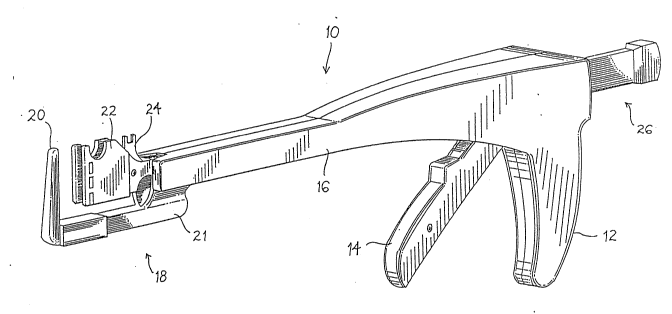
Figure 1 illustrates a perspective view of a surgical
fastening instrument employing the adjustable closure mechanism of
the present invention;
Figure 2 illustrates a partial enlarged side cross
sectional plan view of the handle end of a surgical instrument
employing a first embodiment of the adjustable closure mechanism
of the present invention in which the instrument is at an at rest
condition;
Figure 3 illustrates a partial enlarged side cross
sectional plan view of the device of Figure 2 in which the
adjustable closure mechanism of the present invention is fully
deployed so that the device is in the fully loaded condition;
~Q7~3~
--10--
Figure 4 illustrates a partial enlarged side cross
sectional plan view of the handle end of the surgical instrument
of Figure 2 in which the release mechanism has been activated to
disengage the retaining means and the adjustable closure
mechanism;
Figures 5a and 5b illustrate a side plan view and a top
plan view, respectively, of the pusher bar mechanism of the
adjustable closure mechanism of Figure 2;
Figure 6 illustrates a partial enlarged side cross
sectional plan view of the handle end of a surgical fastening
instrument in a rest condition employing a first embodiment of the
adjustable closure mechanism of the present invention;
Figure 7 illustrates a side cross sectional plan view of
a surgical fastening instrument employing the adjustable closure
mechanism of Figure 6 in which the instrument is in an at rest
condition;
Figure 8 illustrates the device of Figure 6 in which the
adjustable closure mechanism is activated and the jaw mechanism is
partially closed;
Figure 9 illustrates a device of Figure 6 in which the
adjustable closure mechanism of the present invention is fully
deployed so that the device is in the fully loaded condition;
Figure 10 illustrates the device of Figure 6 in which
the adjustable closure mechanism of the present invention is fully
deployed and the trigger mechanism of the device has been actuated
so that the fastening means havé been driven from the cartridgei
Figure 11 illustrates a top plan view of the adjustable
closure mechanism of Figure 6;
Figure 12 illustrates a perspective view of a surgical
fastening instrument employing a further embodiment of the
adjustable closure mechanism of the present invention;
Figure 13 illustrates a partial enlarged side cross
sectional plan view of the handle end of the surgical fastening
instrument of Figure 12 employing the alternate embodiment of the
adjustable closure mechanism of the present invention in which the
instrument is in an at rest condition;
207~
Figure 1~ illustrates a partial enlarged side cross
sectional plan view of the handle end of the surgical fastening
instrument in which the adjustable closure mechanism of the
present invention is fully deployed so that the device is in the
fully loaded condition;
Figures 15a through 15c illustrate the coupling
mechanism according to the present invention for coupling the
trigger mechanism to the fastener driving mechanism used in
conjunction with the adjustable closure mechanism of the present
invention;
Figures 16a and 16b illustrate a side plan view and a
front plan view, respectively, of a first embodiment of the
retaining means of the adjustable closure mechanism of the present
invention; and
Figures 17a and 17b illustrate a side plan view and a
front perspective view, respectively, of a second embodiment of
the retaining means of the adjustable closure mechanism of the
present invention.
D D~SCRIPTION OF THF PR~F~RR~D EMBODIMENTS
Referring now in specific detail to the drawings, in
which like reference numerals identify similar or identical
elements throughout the several views, Figure 1 shows a surgical
fastening instrument 10 which employs the adjustable closure
mechanism of the present invention. Fastening instrument 10 is
provided with a stationary handle 12 and an actuating handle 14
which together comprise the trigger mechanism of instrument 10.
An elongated body portion 16 is provided which terminates in a
distal jaw mechanism 18 which includes an anvil jaw 20 and a
cartridge jaw 22. A fastening cartridge (not shown) is positioned
within cartridge jaw 22 for driving staples or fasteners through
tissue against an anvil surface or into fastener retainers
positioned on anvil jaw 20. At the handle end of instrument 10 is
provided advancing mechanism 26 for advancing the approximating
....... ,_~ .~
-12- 207~73~
mechanism disposed within body portion 16 whose function will be
described below.
AS seen in Figure 2, the adjustable closure mechanism
according to a first embodiment of the present invention is shown.
Pusher bar mechanism 28 is pivotably secured to the instrument at
pivot point 36, and includes advancing means for adjusting or
approximating the spacing between cartridge jaw 22 and anvil jaw
20. A first advancing means comprises the combination of first
advancing pawl 30 which engages first advancing ratchet 40 which
is secured to removable rod member 38. The second advancing means
comprises a second advancing pawl 32 which engages a second
advancing ratchet 42, where pawl 32 is also disposed on movable
rod 38. Pusher bar mechanism 28 is shown in detail in Figures 5a
and 5b, and it can be seen that pawl members 30 and 32 are spring
biased through the provision of spring members 29 and 33,
respectively. Spring member 29 biases pawl member 30 by abutting
against post member 31 as shown; spring member 33 biases pawl
member 32 by abutting its respective post member 31. A release
block 34 is provided on advancing mechanism 28, whose function
will be discussed below. Movable rod member 38 passes through a
retaining mechanism 44, and is secured to fastener driver 62 and
cartridge frame 64 to advance these elements in a distal direction
to approximate the distance between cartridge jaw 22 and anvil jaw
20. Retaining mechanism 44 is shown in detail in Figures 16a and
16b, as well as Figures 17a and ~7b. Retaining mechanism 44 is
biased into the engaged position by spring
member 54, and may be moved to a disengaged position by release
rod 56 which is slidably mounted in support blocks 58.
Ratchet 40 and pawl member 30 comprise the first
advancing means which approximates the distance between the jaw
members an initial distance. The second advancing means comprises
ratchet 42 and pawl member 32 which advance the jaw members a
second distance subsequent to approximation by the first advancing
means. As can be seen in the drawings, the teeth of ratchet 40
are much larger than the teeth of ratchet 42, and thus provide for
greater movement of the jaws than the smaller teeth of ratchet 42.
-13- 207~7a~
Retaining mechanism 44 comprises a clamp member 46 which
is pivotably mounted on a carriage member 50 and is biased into
the engaged position by biasing spring 54. As best seen in Figure
16a and 16b, a block member 48 is provided having a shoulder
portion 52 which provides a pivot point for clamp member 46.
Clamp member 46 may include a spring post 47 as shown which
engages biasing spring 54. Clamp member 46 further includes a
central bore 70 through which movable rod 38 passes. In alignment
with central bore 70 is a central bore 72 of block member 48
through which movable rod 38 also passes. A release bore 74 is
also provided in block member 48 to allow release rod 56 to pass
through and contact the upper portion of clamp member 46.
Figures 17a and 17b illustrate an alternate embodiment
of retaining mechanism 44. The embodiment of Figure 17a is
identical to the embodiment of 16a except for the provision of a
leaf spring 55 which provides the biasing force on clamp member 46
instead of biasing spring 54.
The operation of the adjustable closure mechanism of
Figure 2 will now be described. After the tissue to which the
surgical fasteners are to be applied is positioned between
cartridge jaw 22 and anvil jaw 20, cartridge jaw 22 is advanced
distally to grip the tissue therebetween by activating advancement
means 26. Pusher bar mechanism 28 is pivotably actuated by
pumping pusher bar mechanism 28 repeatedly in the direction of
arrow A. This motion causes pawl member 30 to engage ratchet 40
to urge movable rod 38 in the direction of arrow B. Movable
rod 38 is prevented from moving rearwardly by retaining mechanism
44. As pusher bar mechanism 28 is pumped in the direction of
arrow A, pawl member 30 engages successive teeth of ratchet 40 to
move rod member 38 forwardly. Moving movable rod 38 forwardly
causes fastener driver 62 and cartridge frame 64 to move forwardly
as cartridge jaw 22 moves towards anvil jaw 20 to grip the tissue
therebetween. When pawl member 30 is engaged in the last tooth of
ratchet 40 at the proximal end of ratchet 40, pawl member 32
engages the first tooth at the distal end of
- ~ ~ ....
-14- 2~7~3~
ratchet 42. Ratchet 42 and pawl member 32 provide for incremental
adjustment of the distance between cartridge jaw 22 and anvil jaw
20 and moves movable rod 38 over small distances compared to the
distance traversed through the cooperation between pawl member 30
and ratchet means 40.
As movable rod 38 urges fastener driver 62 and cartridge
frame 64 forwardly, coupling arm 60, as best seen in Figures 15a
through 15c, slides along bearing surface 66 of fastener driver 62
until the jaws are approximated at the desired distance, when
coupling arm 60 is engaged in notch 68 to permit driving of the
fasteners into the tissue. This position is clearly seen in
Figure 3. At this point, actuating handle 14 may be moved towards
stationary handle 12 to fire the fasteners into the tissue.
After the fasteners are driven into the tissue, the
adjustable closing mechanism, and the cartridge jaw, may be
returned to the position shown in Figure 2 by releasing the
retaining mechanism 44. As best seen in Figure 4, this is
accomplished by pivoting the pusher bar mechanism 28 in the
direction of arrow C so that release block 34 is moved in the
direction of the arrow C_. Release block 34 engages the rear end
of release rod 56 which urges release rod 56 forwardly through
support blocks 58 and against the upper portion of clamp member
46. Clamp member 46 is moved in the direction of arrow D to
disengage the edges of central bore 70 from movable rod 38.
Release block 34 also lifts support blocks 58 to lift ratchet
mechanisms 40 and 42 away from pawl members 30 and 32,
respectively, to allow movable rod 38 to move rearwardly in the
direction of arrow E to return the instrument to the at rest
position shown in Figure 2.
Figures 6-11 illustrate an alternate embodiment of the
adjustable closure mechanism of the present invention. A pusher
bar mechanism 80 is provided at the handle end of the instrument
for operating the advancing mechanism 82 to approximate the
distance between cartridge jaw 22 and anvil jaw 20. Similar to
advancing mechanism 28 above, advancing mechanism 82 as shown in
Figure 6 comprises a first advancing means for approximating the
?
-15- 2~7~
cartridge jaw 22 in relation to anvil jaw 20 a large distance, and
also includes a second advancing means for incrementally advancing
cartridge jaw 22 towards anvil jaw 20 subsequent to the initial
movement.
Pusher bar mechanism 80 is secured to the advancing
mechanism 82 and is further secured to cartridge frame advancing
rod 98 for advancing cartridge jaw 22 towards anvil jaw 20.
Fastener driver 62 is secured to cartridge frame advancing rod 98
through a linkage arrangement which includes a driving link 102,
and a driving pin 106 whose function will be described below.
The operation of advancing mechanism 82 will now be
described in reference to drawing Figures 7-10. As best seen in
Figure 7, the instrument is in an at rest position where cartridge
jaw 22 and cartridge 114 are positioned away from anvil jaw 20.
Driving pin 106 is positioned at the proximal end of frame track
108, and coupling arm 60 is positioned on bearing surface 66 of
fastener driver 62. Once tissue to be fastened or stapled is
positioned between the cartridge jaw 22 and anvil jaw 20, pusher
bar mechanism 80 is urged forwardly in the direction of arrow F as
best seen in Figure 8. Advancement of pusher bar mechanism 80 in'
the direction of arrow F comprises the first advancing means of
advancing mechanism 82. The advancing pawl means 84 and advancing
pawl means 86 slide over ratchet means 88 due to the forward
movement of pusher bar mechanism 80. When resistance to further
forward movement of the cartridge 114 and cartridge jaw 22, which
are moved in a direction of arrow F_, is felt by the surgeon,
movement of the pusher bar mechanism 80 in the direction of arrow
F is ceased. As can be clearly seen in
Figure 8, movement of pusher bar mechanism 80 causes movement of
fastener
driver 62 which causes coupling arm 60 to slide along bearing
surface 66 as shown. Driving pin 106 travels along frame track 108
to the point shown in Figure 8, whereby the driving link 102 urges
the alignment pin advancement means 24 forwardly, which in turn
causes alignment pin 116 to be moved through cartridge 114 towards
an alignment hole in anvil jaw 20 (not shown). Alignment pin 116
-16- ~7~7~
cooperates with the alignment hole in anvil jaw 20 to provide for
proper alignment of the fasteners with the anvil surface on anvil
jaw 20. Anvil jaw 20 may also include means for holding a
plurality of retainers which engage fasteners loaded in
cartridge 114. Biasing spring 100 begins to extend as shown in
Figure 8.
once resistance due to the tissue positioned between the
jaw members has been encountered, cartridge jaw 22 may be further
advanced by using the second advancement means to provide for fine
adjustment of the spacing between the jaw members. In order to
accomplish this, as best seen in Figure 9, pusher bar mechanism 80
is reciprocatingly pivoted in the direction of arrow G to urge
cartridge frame advancing rod 98 forwardly by using advancing pawl
means 84 and advancing pawl means 86, which engage ratchet means
88. Pawl means 84 and 86 remain in engagement with ratchet means
88 through the provision of pawl spring 94.
Referring to Figure 11, it can be seen that advancing
pawl means 84 comprises a plurality of pawl members, in this
instance three, namely pawl members 84a, 84b and 84c. Pawl
members 84a, 84b and 84c successively and incrementally move
cartridge frame advancing rod 98 once each prior to movement of
advancing pawl member 86. Preferably, each pawl member 84a, 84b
and 84c move rod 98 0.039 inches so that when each pawl member
84a, 84b and 84c has moved successively, advancing pawl member 86
then moves 0.10 inches. Pawl member 86 serves as a retaining
mechanism to prevent rod member 98 from moving rearwardly due to
biasing spring 100 while each pawl member 84a through 84c are
moving. Continued pumping of push bar mechanism 80 in the
direction of arrow G will incrementally move cartridge jaw 22 and
cartridge 114 towards anvil jaw 20.
As the distance between the jaw members is set to a
desired distance, driving pin 106 moves to the distal end of frame
track 108 so that drive link 102 assumes a substantially vertical
position as shown in Figure 9. This draws alignment pin advancing
means 24 slightly rearwardly so that alignment pin 116 engages the
hole in anvil jaw 20 but does not extend beyond the jaw as shown.
2 0 7-9 7 3 6
Cartridge frame advancing rod 98, cartridge jaw 22, and cartridge
114 are now in position for firing. At this point, due to the
movement of driving pin 106, fastener driver 62 has moved into
position to fire the fasteners into the tissue. This can be seen
by the engagement of coupling arm 60 in notch 68 of fastener
driver 62. Coupling arm 60 has slid off bearing surface 66 and
into notch 68 so that the fasteners may be fired.
Fasteners 120 are driven into the tissue by moving
actuating handle 14 in the direction of arrow H as shown in Figure
10. Coupling arm 60 moves fastener driver 62 forwardly in the
direction of arrow I to drive the fasteners 120 into the tissue.
After firing, actuating handle 14 is returned to its at rest
position by biasing spring 110. In order to release the jaws to
remove the instrument from the surgical site, pusher bar mechanism
80 is pivoted upwardly in the direction of arrow J against biasing
spring 90 about pivot point 92 which pivots pawl means 86 away
from ratchet means 88. Release extension 96, in conjunction with
pawl spring 94 pivots pawl means 84a through 84c away from ratchet
means 88 to release the entire mechanism and return the instrument
to the position shown in Figure 7.
Figures 12 through 14 illustrate a surgical fastening
apparatus 130 employing a further embodiment of the adjustable
closure mechanism of the present invention. Device 130 includes
actuating handle 14, stationary handle 12, and body portion 16
which terminates in a jaw mechan~sm 18 similar to that described
above. Jaw mechanism 18 includes an anvil ~aw 20, a movable
cartridge jaw 22, and an alignment pin advancement means 24
similar to that described above. Instrument 130 further includes
a first advancing means 132 and a release bar 134 for releasing a
retaining mechanism which will be described below.
Turning now to Figures 13 and 14, there is illustrated
the retaining mechanism 44 which is similar to that described
above. Retaining mechanism 44 includes a clamp member 46 to which
release bar 134 is attached. Retaining mechanism 44 further
includes block member 48 having shoulder 52, all of which are
-18- 2~7~7~
mounted to carriage 50 as described above and best shown in
Figures 16a and 16b and 17a and 17b.
First advancing means 132 comprises a pusher knob 136
for advancing an advancing rod 138 into the housing of instrument
130. In use, pusher knob 136 is urged forwardly in the direction
of arrow K to move advancing rod 138 forwardly. Advancing rod 138
further includes second advancement means 140, which comprises
screw threads 141, whose function will be described below.
Advancing rod 138 and screw thread~ 141 pass through central bore
70 of clamp member 46 and central bore 72 of block member 48 and
terminate in universal joint 142 which is attached to cartridge
frame 144 and fastener driver 62 whose functions are identical to
that described above.
Turning now to Figure 14, advancing rod 138 is moved
forwardly until clamp member 46 engages screw threads 141. At
this point, cartridge jaw 22 has been approximated a great
distance towards anvil jaw 20 to grip tissue therebetween. Pusher
knob 136 may then be rotated by the thumb of the surgeon in the
direction of arrow L to further advance cartridge jaw 22 towards
anvil jaw 20, since the rotational motion is for fine adjustment
of the spacing over a small distance. Rotation of pusher knob 136
allows advancing rod 138 to further move forwardly through the
cooperation of screw threads 141 with central bore 70 of clamp
member 46. The rotational movement of rod 138 is translated into
longitudinal movement through the provision of universal joint
142. After the jaws have been approximated to a desired distance,
coupling arm 60 engages notch 68 of fastener driver 62 and
actuating
handle 14 may be moved towards stationary handle 12 to fire the
fasteners into the tissue. The following firing of the fasteners,
the entire mechanism may be released and returned to its at rest
position by moving release bar 134 in thè direction of arrow M to
disengage screw threads 141 from central bore 70. Release bar 134
moves in the direction of arrow M against biasing spring 146 which
maintains engagement of central bore 70 with rod member 138.
-19- ~(~797~~
The adjustable closure mechanism of the present
invention can also be used in other instruments to close the
distance between the movable jaw member and the stationary jaw
member at the stapling or fastening end of the instrument or
between two movable jaw members. That is, the jaw mechanism may
be of the type wherein one jaw moves toward and away from the
other; however, the present invention is also applicable for use
with devices of alternative types, i.e., where both jaws move
toward and away from each other. The surgical instrument may be
of the type which applies metal staples or two-part fasteners of
the bioabsorbable type.
The surgical stapling or fastening instrument employing
the adjustable closure mechanism of the present invention is a
device which may be operated with one hand to effect the closure
motion of the jaw members of the instrument followed by activation
of the trigger mechanism to fire the staples or fasteners into the
tissue. The complex rotational or pivoting arrangement of the
prior devices is eliminated, resulting in a lightweight and easy
to handle instrument which is inexpensive to manufacture and easy
to assemble.
While the invention has been particularly shown and
described with reference to the preferred embodiments, it will be
understood by those skilled in the art that various modifications
and changes in form and detail may be made therein without
departing from the scope and spirit of the invention.
Accordingly, modifications such as those suggested above, but not
limited thereto, are to be considered within the scope of the
lnvent lon .