Note: Descriptions are shown in the official language in which they were submitted.
METHOD OF ESTIMATING VEHICLE VELOCITY AND
METHOD OF AND SYSTEM FOR CONTROLLING BRAKES
BACKGROUND OF THE INVENTION
Field of the Invention:
The present invention relates to a method of and
an apparatus for estimating a vehicle velocity, which
are suitable for use in a vehicle having drive wheels
and follower wheels, and to a method of and a system
for controlling brakes, wherein when a braking
force to be applied to each of the brakes is estimated
from a wheel slip ratio and a wheel acceleration~
deceleration so as to control each brake or when
braking is changed from antilock braking to normal
braking, the optimum brake pressure increasing rate can
be set upon increase in the brake pressure and the
braking force can be controlled based on the optimum brake
pressure increasing rate, thereby making it possible to
ensure satisfactory control feeling.
Description of the Related Art:
In a vehicle such as a motorcar, a motorcycle or
the like, a so-called brake control system is used in which
a speed or velocity of each wheel placed under braking
is compared with a vehicle speed and controlling of brakes
is effected based on the result of comparison. In the
brake control system, a slip ratio is determined from the
wheel velocity and the vehicle velocity. When the slip
1 2
ratio reaches a target slip ratio or above, the slip
ratio is reduced by decreasing brake hydraulic pres-
sure, thereby producing the optimum braking force.
Further, a driving force control apparatus is
known which controls a driving force of an engine by
adjusting the ignition timing of the engine upon a vehicle
rapid start or depending on a variation in a friction
coefficient of a road surface, for example. Even in the
case of the driving force control apparatus, the wheel
velocity and the vehicle velocity are used as data.
Now, the wheel velocity, i.e., the rotational
speed of each wheel can be directly detected by a
sensor. It is however difficult to directly detect the
vehicle velocity by a sensor. It is also next to im-
possible to detect the velocity of a vehicle such as a
motorcycle whose weight and size are greatly
restricted to accommodate the sensor therein.
Accordingly, a method is normally used which estimates
the vehicle velocity from the wheel velocity.
However, there is often a situation in which an
estimated vehicle velocity is set to be larger or smaller than
an actual vehicle velocity under the conditions in which
each wheel slips against the road surface. In this
case, the brake control system or the driving force
control apparatus tend to effect unsuitable control.
A brake control system is known, in which a slip ratio
of each wheel against a road surface is computed from
h {~
the speed or velocity of a running vehicle and the
rotational speed of each wheel and the optimum braking
force is applied to the vehicle based on the computed slip
ratio. As an example of such a system, a control logic
circuit of which is shown in FIG. l. In FIG. l, each
of an inlet valve and an outlet valve is a hydraulic control
valve for controlling hydra~lic pressure applied to a caliper
cylinder (hereinafter called "caliper pressure") to operate
a pair of calipers which hold each brake disk therebetween.
In the same drawing, each of Al, A2 and A3
represents a slip ratio of each wheel against the road
surface. They have a relationship of ~1<~2<A3. Each
~f ~ 2 and ~3 represents a wheel acceleration and
each ~f -~1 and -~2 represents a wheel deceleration.
These values have a relationship of -~2<-~1C~<~1<~2<~3.
Now, a parameter represented by -~1 and -~2 is changed
from "O" to "1" when each of the wheel decelerations
has reached a set value (threshold value) or less.
Each of parameters other than the parameter referred to
above is changed from "O" to "1" when each deceleration
has reached the threshold value or more. In the case
of the slip ratio, on the other hand, outputs appear on
signal lines or conductors set by ~1~ A2 and A3 respec-
tively when the slip ratio has reached each of given
slip ratios (Al, A2 and A3) or above tthreshold value
or above).
The inlet and outlet valves are normally "closed"
2 ~
and "opened~ s shown in FIG. 2, the caliper pressure
is reduced (i.e., a decrease in the caliper pressure is
made) when the inlet and outlet valves are operated.
Further, the caliper pressure is raised (i.e., an in-
crease in the caliper pressure is made) when the inlet
and outlet valves are non-operated. The caliper pres-
sure is kept constant when only the outlet valve is op-
erated.
In the prior art, the brake control is effected
by setting the threshold value to each of the slip
ratio and the acceleration/deceleration and determining
whether or not the actual state of each wheel, i.e.,
the slip ratio and the acceleration/deceleration are
the threshold value or above (less) respectively. It
is thus necessary to set processing time as short as
possible and to improve the operating speed of an ac-
tuator which executes the process referred to above.
However, a limitation is imposed on the operating speed
of the actuator and an improvement in its operating
speed is actually difficult.
In the vehicles such as the motorcar, the motor-
cycle, etc., a brake control system provided with a
modulator for the antilock braking is used to control
brakes.
The modulator, which is incorporated into the
motorcycle, for example, comprises an input hydraulic
chamber which communicates with a master cylinder, for
h Q ~ 2
converting a brake operating instruction generated by
the operation o~ a lever by a driver or the depression
of a pedal by the driver into hydraulic pressure or
power, an output hydraulic chamber which communicates
with a caliper cylinder, for applying a braking force
to a brake disk of each wheel (hereinafter called as
"caliper force"), a cut valve for cau~ing the input
hydraulic chamber to communicate with the output hydraulic
chamber and for cutting off the comm~nication between
the input and output hydraulic chambers, an expander
piston disposed on the output hydraulic chamber side
for closing the cut valve upon antilock braking and for
increasing the vol~me of the output hydraulic chamber
so as to reduce the hydraulic pressure or power, and a
crank member held in abutment against the expander
piston and rotatable by a rotative drive source.
In the modulator, the caliper pressure is reduced
by displacing the expander piston so as to increase
the volume of the output hydraulic chamber to avoide a
locked state of each wheel ~pon braking. When the risk
of the locked state is avoided, the eY~pander piston
is displaced to open the cut valve, thereby effecting
normal braking.
In the prior art, however, when the ~raking is
changed from the an~ilock braking to the normal brak-
ing, caliper pressure Pc is abruptly raised toward
~a~ ~ ~
~aster pressure Pm developed in the master cylinder at
the maximum pressure increasing rate as indicated by
the broken line defined between Q and R in FIG. 3.
When a vehicle travels from a road surface
having a low Lriction coefficient (hereinafter called a
"low ~ road") with respect to each wheel to a road
surface having a high friction coefficient (hereinafter
called a "high ~ road") with respect to each wheel
while the antilock control is being effected during the
braking of the vehicle, the front wheel first comes
across to the high ~ road. Thus, a gripping force
of the front wheel is raised so that the slip ratio is
reduced, thereby enabling control for increasing the
brake pressure. However, the rear wheel is still placed
on the low ~ road. Therefore, when the caliper pres-
sure Pc applied to the front wheel is simply raised at
the maximum pressure increasing rate, the braking
forces of the front and rear wheels against the road
greatly differ frorn each other. This tends to hurt the
control feeling. It is thus preferable to maintain
the pressure increasing rate at a given value until the
rear wheel reaches the high ~ road.
A modulator provided with a double-structure type
cut valve having a dual orifice defined therein is
therefore known as has been disclosed in Japanese
Patent Application Laid-Open Publication No. 49-15874
(which corresponds to U.5.P. 3,836,207). However, this
modulator is also actuated by the pressure difference
develo~ed in hydraulic pressures, between the
input hydraulic chamber and the output hydraulic cham-
ber. Therefore, the pressure increasing rate is
restricted and hence various pressure increasing rates
suitable for the conditions of the road surface or the
state of braking cannot be realized.
SUMMARY OF THE INVENTION
It is a principal object of the present invention
to provide a method of and an apparatus for estimating
a vehicle speed, which are suitable for use in a
vehicle, wherein a desired vehicle speed required to
control brakes and brake driving forces or the like can
be estimated easily and with high accuracy.
It is another object of the present invention to
provide a method of and a system for controlling
brakes, wherein a braking force which is applied to
each of the brakes can be easily and accurately
estimated based on a wheel acceleration/deceleration
and a slip ratio, thereby making it possible to effect
the optimum brake control.
It is a further object of the present invention
to provide a method of and a system for controlling
brakes, wherein satisfactory control feeling can be
reliably achieved without regard to the conditions of a
road surface or the state of braking when an increase
in a caliper pressure is e~fected.
, 2
It is a still further object of the present in-
vention to provide a method of estimating a vehicle
velocity, which is suitable for use in a vehicle, the
method comprisiny the following steps: a first step of
determining velocities of drive wheels and follower
wheels of the vehicle, a second step of selecting the
fastest one of the velocities determined in the first
step, a third step of estimating the velocity of the
vehicle based on the fastest wheel velocity selected in
the second step, and a fourth step of repeatedly ex-
ecuting the first through third steps at given time in-
tervals and setting the estimated vehicle velocity
determined immediately before the third step as an
estimated vehicle velocity to be determined in the
fourth step when the estimated vehicle velocity
determined in the third step is faster than the fol-
lower wheel velocities determined in the first step and
lower than the fastest wheel velocity selected in the
second step.
It is a still further object of the present in-
vention to provide an apparatus for estimating a
vehicle velocity, which is suitable for use in a
vehicle. The apparatus comprises first wheel velocity
detecting means for detecting velocities of drive
wheels, second wheel velocity detecting means for
detecting velocities of follower wheels, wheel velocity
selecting means for selecting the fastest one of the
8 --
Q ~
respective wheel velocities detected by the first and
second wheel velocity detecting means, vehicle velocity
estimating means for estimating the velocity of the
vehicle based on the fastest wheel velocity selected by
the wheel velocity selecting means, vehicle velocity
storing means for storing therein the vehicle velocity
estimated by the vehicle velocity estimating means, and
comparing means for comparing the vehicle velocity
stored in the vehicle velocity storing means and the
follower wheel velocities detected by the second wheel
velocity detecting means. The vehicle velocity
estimating means is activated to estimate a desired
vehicle velocity supposing the amount of change of the
estimated vehicle velocity into the high-velocity side
to be zero when it is determined based on the result of
comparison by the comparing means that the vehicle
velocity is faster than the velocities of the follower
wheels.
It is a still further object of the present in-
vention to provide a method of controlling brakes,
wherein the stability of'running of a vehicle and the
state of braking applied to the vehicle are controlled
by adjusting caliper pressure accordi,ng to the state of
running of the vehicle. The method comprises the steps
of determining slip ratios of wheels, determining ac-
celerations and decelerations of the wheels, and
estimating the amounts of increase and decrease in the
. J~ ~
caliper pressure from a mem~ership function in which the
determined slip ratios and the determined accelerations
and decelerations are set as inputs.
It is a still further object of the present in-
vention to provide a method of controlling brakes,
wherein the membership function is changed depending on
characteristics of tires fixed onto the wheels.
It is a still further object of the present in-
vention to provide a method of controlling brakes,
wherein the membership function is changed depending on
the running stability of the vehicle.
It is a still further object of the present in-
vention to provide a system for controlling brakes,
wherein the stability of running of a vehicle and the
state of braking applied to the vehicle are controlled
by adjusting caliper pressure according to the state o~
running of the vehicle. The system comprises wheel ac-
celeration/deceleration detecting means for detecting
an acceleration and a deceleration of each wheel, slip
ratio computing means for computing a slip ratio with
respect to the surface of a road traveled by each
wheel, storing means for storing a table therein as in-
formation, the table including the amounts of increase
and decrease in the caliper pressure~ which have been set
so as to correspond to the value of the detected ac-
celeration/deceleration and the value of the computed
slip ratio, and caliper pressure controlling means for
-- 10 --
h ~
increasing and decreasing the caliper pressure according
to the amounts of increase and decrease in the caliper
pressure, which have been set based on the table from
the wheel acceleration/deceleration and the slip ratio.
It is a still further object of the present in-
vention to provide a system for controlling brakes,
wherein the table is set based on membership functions
corresponding to the wheel acceleration/deceleration
and the slip ratio.
It is a still further object of the present in-
vention to provide a system for contrclling brakes,
wherein the table is set so as to bring the value of
the wheel acceleration/deceleration and the value of
the slip ratio into high resolution in the vicinity of
target values to which the wheel accelera-
tion/deceleration and the slip ratio converge and so as
to bring same into low resolution as the wheel ac-
celeration/deceleration and the slip ratio are sepa-
rated from the convergent target values.
It is a still further object of the present in-
vention to provide a system for controlling brakes,
wherein the table is set so as to bring the values of
the slip ratio and the acceleration/deceleration into
the low resolution along directions in which the ab-
solute values of the slip ratio and the acceleration/
deceleration increase from O slip ratio and O wheel ac-
celeration/deceleration respectively.
~ Q ~ 2
It is a still further object of the present in-
vention to provide a method of controlling brakes,
wherein caliper pressure is transmitted to a caliper
cylinder ~rom a master cylinder depending on an input
supplied by operating a brake lever or a brake pedal or
the like, thereby effecting normal braking for applying
a braking force to each wheel, and a cut valve is displaced
upward and downward by an expander piston movable in
upward and downward directions by a driving means so as to
be closed, thereby cutting off the caliper cylinder from
communicating with the master cylinder and adjusting the
volume of an output hydraulic chamber which communicates
with the caliper cylinder so as to effect antilock braking
for controlling the caliper pressure. The method compriese
the steps of controlling the caliper pressure which is applied
to each wheel to thereby effect the antilock braking, and
moving the expander piston upward and downward upon the
antilock braking so as to repeatedly open and close the cut
valve at given time intervals, thereby i.ncreasing the
caliper pressure at a target pressure increasing rate.
It is a still further object of the present in-
vention to provide a method o~ controlling brakes,
wherein caliper pressure is transmitted to a caliper
cylinder from a master cylinder depending on an input
supplied by operating a brake lever or a brake pedal or
the like, thereby effecting normal braking for applying
a braking force to each wheel, and a cut valve is
- 12 -
~ ~ g ~3 1, 1 ~
displaced upward and downward by an expander piston movable
in upward and downward directi.ons by a dri.ving means so
as to be cJ.osed, ~hereby cut~ing o~f the caliper
cyli.nder from communi.cati.ng with the master cylinder
and adjusting the volume of an output hydraulic chamber
which communicates with the caliper cylinder so as to
effect antilock braking for controlling the caliper
pressu~e. The method comprises the following steps: a
first step of detecting the state of input, a second
step of detecting the state of a road surface, a third
step of setting the rate of increase in the caliper
pressure at the time of the antilock braking, based on
the detected state of input and the detected state of
road surface, and a fourth step of displacing the
expander piston in accordance with the set pressure
incr~asing rate so as to increase the caliper pressure.
It is a still further object of the present in-
vention to provide a method of controlling hrakes,
wherein the second step includes a process for estimat-
ing the state of the road surface from a vehicle ac-
celeration/deceleration.
The above and other objects, features and ad-
vantages of the present invention will become apparent
from the following description and the appended claims,
taken in conjunction with the accompanying drawings in
which preferred embodiments of the present invention
are shown by way of illustrative example.
- 13 -
~ t
BRIEF DESC~IPTI~N OF THE DRAWINGS
FIG. l is a view showing a conventional control
logic circuit;
FIG. 2 is a view for describing control executed
with respect to the outputs of the logic circuit shown
in FIG. 1;
FIG. 3 is a view for describing a caliper pres-
sure increasing rate employed in a brake control method
according to a prior art;
FIG. 4 is a block diagram showing the structure
of a vehicle speed estimating apparatus according to the
present invention, which is suitable for use in a vehicle;
FIG. 5 is a view for describing the relationship
between a wheel speed selected by a wheel speed selec-
ting circuit of the apparatus shown in FIG. 4 and an
estimated vehicle speed determined from a basic comput-
ing process of an estimated vehicle speed computing
circuit;
FIG. 6 is a view for describing the relationship
between the speed of a follow-up wheel, the speed of a
drive wheel, a selected wheel speed and a vehicle speed
estimated and corrected based on these speeds, all of
which are determined by the apparatus shown in FIG. 4;
FIG. 7 is a view for describing the relationship
between the speed of the follow-up wheel, the speed of
the drive wheel, the selected wheel speed and the
vehicle speed estimated and corrected based on these
speeds, all of which are determined by the apparatus
- 14 -
h ~ 2
shown in FIG. 4 upon brake control;
FIG. 8 is a schematic view illustrating the
structure of a system for effecting a brake control
method according to the present invention;
FIG. 9 is a schematic exterior view depicting a
motorcycle in which the brake control system shown in
FIG. 8 is to be incorporated;
FIG. 10 is a view for describing a fuzzy map
employed in the brake control method according to the
present invention;
FIG. 11 is a view for describing a membership
function of a slip ratio;
FIG. 12 is a view for describing a membership
function of an acceleration/deceleration;
FIG. 13 is a view for describing a membership
function of caliper pressure;
FIG. 14 is a view for describing the relationship
between a wheel speed and caliper pressure both
employed in the present invention and those employed in
the prior art;
FIG. 15 is a view for describing characteristics
of different tires;
FIG. 16 is a view for describing a membership
function of a slip ratio, based on the characteristics
of the different tires;
FIG. 17 is a view for describing a membership
function of a slip ratio, based on characteristics of a
vehicle having excellent running stability and normal
vehicle characteristics;
FIG. 18 is a schematic view showing the structure
of a brake control system according to another embodi-
ment of the present invention;
FIG. 19 is a view for describing a table employed
in the brake control system shown in FIG. 18;
FIG. 20 is a view for describing the relationship
between a slip ratio and the number of addresses or an
interval for setting the amount of increase or decrease
in pressure, all of which are represented in the table
employed in the brake control system shown in FIG. 18;
FIG. 21 is a view for describing the relationship
between a wheel acceleration/deceleration and the num-
ber of addresses or an interval for setting the amount
of increase or decrease in pressure, all of which are
represented in the table employed in the brake control
system shown in FIG. 18;
FIG. 22a is a view for describing the rela-
tionship between a slip ratio and the amount of in-
crease and/or decrease in caliper pressure, which are
shown in the table employed in the brake control system
shown in FIG. 18;
FIG. 22b is a view for describing the rela-
tionship between a slip ratio and the amount of in-
crease and/or decrease in caliper pressure, the view
being illustrated as a comparative example of the view
- 16 -
~ $ ~
depicted in FIG. 22a;
FIG. 23 is a view for describing a method of con-
trolling brakes, according to the present invention;
FIG. 24 is a view for describing the comparison
between a caliper pressure increasing rate employed in
the prior art and that employed in the present inven-
tion;
FIG. 25 is a schematic view illustrating the -
overall structure of a brake control system according
to a further embodiment of the present invention, for
performing a brake control method according to the
present invention;
FIG. 26 is a view for describing the manner of
operation of a cut valve mechanism employed in the
brake control system shown in FIG. 25;
FIG. 27 is a view for describing the manner of
another operation of the cut valve mechanism employed
in the brake control system depicted in FIG. 25;
FIG. 28 is a view for describing the manner of a
further operation of the cut valve mechanism employed
in the brake control system shown in FIG. 25;
FIG. 29 is a flowchart for describing an overall
control routine which is executed in the brake control
method according to the present invention;
FIG. 30 is a flowchart for describing vehicle
deceleration control which is executed in the brake
control method according to the present invention;
- 17 -
2 ~
FIG. 31 is a flowchart for describing break-
through control which is executed in the brake control
method according to the present invention;
FIG. 32 is a view showing the result of control
effected under a high ~ road by the brake control meth-
od according to the present invention;
FIG. 33 is a view illustrating the result of con-
trol effected under a ~ jump by the brake control meth-
od according to the present invention;
FIG. 34 is a view depicting the result of control
on a repetitive input by the brake control method ac-
cording to the present invention;
FIG. 35 is a view for describing the setting of a
target crank angle by the brake control method accord-
ing to the present invention; and
FIG. 36 is a view for describing an increasing
rate of caliper pressure which has been controlled by
the target crank angle shown in FIG. 35.
DETAILED DESCRIPTION OF THE PREFERRED EMBODIMENTS
A method of and an apparatus for estimating a
vehicle speed or velocity, according to the present in-
vention, which are suitable for use in a vehicle, will
hereinafter be described in detail with reference to
the accompanying drawings in which preferred embodi-
ments are shown by way of illustrative example.
FIG. 4 is a block diagram showing a vehicle speed
-- 1~ --
estimating apparatus accordin~ to the present embodi-
ment. The vehicle speed estimating apparatus comprises
a follower wheel rotational speed sensor for detecting
the rotational speed or velocity of each of follower or
follower wheels (e.g., a front wheel of a motorcycle,
i.e. a 2-wheeled automotive vehicle), a drive wheel
rotational speed sensor 2 for detecting the rotational
speed or velocity of each of drive wheels (e.g., a rear
wheel of the motorcycle), wheel speed computing cir-
cuits 3A, 3B for computing wheel speeds or velocities
based on signals outputted from the follower wheel
rotational speed sensor 1 and the drive wheel rota-
tional speed sensor 2 respectively, a wheel speed se-
lecting circuit (wheel speed selecting means) 4 for se-
lecting the fastest wheel velocity from the wheel
velocities which have been computed by the wheel speed
computing circuits 3A, 3B, an estimated vehicle speed
computing circuit (vehicle speed estimating means) 5
for computing an estimated vehicle speed or velocity
based on the wheel velocity which has been selected by
the wheel speed selecting circuit 4, an estimated
vehicle speed storing circuit (vehicle speed storing
means) 6 for storing the computed estimated vehicle
speed therein as data, and a comparator (comparing
means) 7 for comparing the estimated vehicle speed
stored in the estimated vehicle speed storing circuit 6
with each follower wheel velocity computed by the
-- 19 --
~ ~ ~./' i & ,. t .,
wheel speed computing circuit 3A. In this case, the
output of the comparator 7 is used to control the
estimated vehicle speed computing circuit 5.
Incidentally, the fol~ower wheel rotational
speed sensor 1 and the wheel speed computing circuit 3A
serve as a first wheel speed detecting means, whereas
the drive wheel rotational speed sensor 2 and the wheel
speed computing circuit 3B serve as a second wheel
speed detecting means.
The vehicle speed estimating apparatus according
to the present embodiment is basically constructed as
described above. A description will now be made of a
method of estimating the speed or velocity of a motor-
cycle, for example, which is carried out by the vehicle
speed estimating apparatus.
First of all, during a period in which the motor-
cycle is running, the follower wheel rotational speed
sensor 1 and the drive wheel rotational speed sensor 2
respectively detect the rotational speeds of the front
and rear wheels as pulses outputted from a rotary en-
coder or the like, for e~ample, and output same to the
corresponding wheel speed computing circuits 3A, 3B.
The wheel speed computing circuits 3A, 3B compute a
follower wheel speed or velocity VwF and a drive wheel
speed or velocity VwR in response to the pulses in-
putted from the follower wheel rotational speed sensor
1 and the drive wheel rotational speed sensor 2 respec-
- 20 -
tively, and output the velocities thus computed to the
wheel speed selecting circuit 4 as data. Incidentally,
the wheel velocities VwF VwR can be obtained by count-
ing the number of pulses outputted from the follwer
wheel rotational speed sensor 1 and the drive wheel
rotational speed sensor 2 and converting same into the
peripheral speeds of the wheels.
The wheel speed selecting circuit 4 then selects
the fastest wheel velocity from the wheel velocities
VwF, VwR and outputs it to the estimated vehicle speed
computing circuit 5 as a wheel velocity VwM. That is,
this selection is made because the fastest wheel
velocity approaches an actual vehicle speed provided
that a slip ratio of each wheel against a road surface
is less than or equal to 0.
The estimated vehicle speed computing circuit 5
basically computes an estimated vehicle speed or
velocity Vref for each given computing period or cycle
(3 ms, for example) in the following manner.
Assuming that the motorcycle is not decelerated
at - 9.8 m/s2 (-lG) or below and not accelerated at +
29.4 m/s2 (+3G) or more, the estimated vehicle speed
computing circuit 5 sets a lower limit deceleration
GDEC and an upper limit acceleration GACc as follows:
GDEC = ~ 9.8 m/s2 ... (1)
GACc = + 29.4 m/s2 . (2)
When a wheel acceleration dVwM~n)/dt falls within a
- 21 -
range of from above GDEC to below GACC' an estima
vehicle velocity Vref(n) is determined as follows:
Vref(n) = VWM(n)
where (n) represents a value obtained upon execution of
an nth computation.
When the wheel acceleration dVwM(n)/dt is reduced
at the low limit deceleration of GDEC or below, the
estimated vehicle velocitY Vref(n) is determined as
follows:
Vref(n) = Vref(n~ GDEC ~-- (4)
where Vref(n-l) represents an estimated vehicle
velocity in the previous computing cycle and ~GDEC
represents a lower limit deceleration corresponding to
the given computing cycle. This equation (4)
represents that the estimated vehicle velocity Vref is
set to the lower limit deceleration GDEC when the wheel
velocity VWM(n) is reduced at the low limit decelera-
tion of GDEC or below.
Similarly, when the wheel acceleration dVwM(n)/dt
is increased at the upper limit acceleration of GACc or
a~ove, the estimated vehicle velocity Vre~(n~ is
determined as follows:
Vref(n) = Vref(n-~ GACC ~5)
where ~GACc represents an upper limit acceleration
corresponding to the given computing cycle. This equa-
tion (5) shows that the estimated vehicle velocity Vref
is set to the upper limit acceleration GACc when the
- 22 -
~ 3 ~
wheel velocity VwM(n) is increased at the upper limit
acceleration of GACc or above.
FIG. 5 shows the estimated vehicle velocity Vref
determined based on the above equations (3), (4) and
(5) when the wheel velocity VwM indicated by the dotted
line is given by the wheel speed selecting circuit 4.
In the present embodiment, the estimated vehicle
velocity Vref determined in the above-described manner
is further corrected by comparing with the follower
wheel velocity VwF. This process will be described be-
low with reference to FIG. 6.
FIG. 6 shows a case in which the acceleration is
made by increasing a driving force of a motorcycle's
engine. The velocity VwR of the rear wheel, which
serves as the drive wheel, abruptly increases with
respect to the velocity VwF of the front wheel which
serves as the follower wheel because the rear wheel is
brought to an idle running state upon its initial ac-
celeration. At this time, the wheel speed selecting
circuit 4 selects the fastest wheel velocity from VwR,
VwF and outputs the velocity VwR o~ the drive wheel to
the estimated vehicle speed computing circuit 5 as the
wheel velocity VwM. When, on the other hand, the
estimated vehicle speed computing circuit 5 computes
the estimated vehicle velocity Vref based on the wheel
veloc.ity VwM as it is, the estimated vehicle velocity
Vref different from an actual vehicle velocity is ob-
tained.
Thus, in the present embodiment, the estimatedvehi.cle velocity Vref(n-l) obtained by the previous
computation is temporarily stored in the estimated
vehicle speed storing circuit 6 as data. Then, the
estimated vehicle velocity Vref(n-l) is compared with a
follower wheel velocity VWF(n) for the present com-
putation in the comparator 7 to thereby correct the
estimated vehicle velocity Vref(n).
That is, the comparator 7 compares the follower
wheel velocity VwF(n) and the estimated vehicle
velocitY Vref(n-l) If the following condition is
satisfied, then a signal for inhibiting the estimate
vehicle velocity Vref from being brought up to date is
outputted to the estimated vehicle speed computing cir-
cuit 5.
Vref(n-l)>vWF~n) and Vref(n-l)~vWF(n) ~-- (6)
Accordingly, the estimated vehicle speed computing cir-
cuit 5 outputs an estimated vehicle velocity Vref(n)
identical to the previous estimated vehicle velocity
Vref(n-l). The estimated vehicle velocity Vref thus
computed is shown in FIG. 6.
When the drive wheel velocity VwR is greater than
the follower wheel velocity VwF, the estimated vehlcle
velocity Vref is changed so as to follow the fol-
lower wheel velocity VwF without following the
fastest wheel velocity. This is because the follower
wheel velocity vwF can provide less slip on a road sur-
face, thereby making it possible to obtain the
estimated vehicle velocity Vref close to the actual
vehicle velocity. As a result, the estimated vehicle
velocity Vref can be computed with higher accuracy.
~ IG. 7 is a view illustrating the relationship
between the follower wheel velocity VwF, the drive
wheel velocity VwR and the estimated vehicle velocity
Vref computed in accordance with the present embodiment
at the time that the brake control system is in opera-
tion. The brake control system determines a slip ratio
from the estimated vehicle velocity Vref and the wheel
velocity VwF or VwR and adjusts a braking force so as
to avoid an increase in the slip ratio, thereby effect~
ing decelerating control. Thus, each of the wheel
velocities VwF, VwR is of a substantially vibration
type as illustrated in FIG. 7. Further, the wheel
velocity VwM, which has been selected by the wheel
speed selecting circuit 4, is represented as indicated
by the dotted line in FIG. 7. On the other hand, the
computed estimated vehicle velocity Vref is represented
as indicated by the solid line in FIG. 7 seeing it in
broad perspective on the analogy of FIG. 6. Inciden-
tally, the estimated vehicle velocity Vref is updated
again upon its deceleration. It is therefore possible
to obtain the estimated vehicle velocity Vref similar
to that shown in FIG. 6.
- 25 -
Thus, the estimated vehicle velocity Vref closest
to the actual vehicle velocity can be obtained. It is
therefore possible to stably and reliably effect the
brake control, for examp]e. The driving force can also
be accurately controlled in addition to the appropriate
brake control. Further, since the control referred to
above can be realized with an extremely simple arrange-
ment, the capacity of a program can be reduced and a
high-speed computation can be effected. It is thus
possible to execute computations at a shorter computing
cycle or period and to achieve an improvement in ac-
curacy.
A description will now be made of a second em-
bodiment which shows a case in which processing time
can be reduced by a brake control method for controll-
ing brake pressure so as to obtain the optimum braking
force.
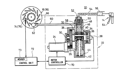
Referring to FIG. 9, reference numeral 10 desig-
nates a 2-wheeled automotive vehicle, i.e., a motor-
cycle. The motorcycle 10 comprises a main body 12, a
handle 14, a front wheel 16 and a rear wheel 18.
A brake control system 20 for carrying out the
brake control method according to the present embodi-
ment is mounted to the motorcycle lO. ~s shown in FIG.
8, the brake control system 20 is provided with an
antilocking modulator 22. A pinion 26 is rotatably
mounted to a d.c. motor 24 of the modulator 22 and
- 26 -
maintained in meshing engagement with a gear 28. The
gear 28 is supported by a crank shaft 30 to which one
end of a crank pin 34 is eccentrically coupled via a
crank arm 32. A potentiometer 38, which serves as a
means for detecting the position of an expander piston
(which will be described later), i.s attached to the
other end of the crank pin 34 via a crank arm 36.
A cam bearing 40 is rotatably mounted on the
crank pin 34. The lower end of the cam bearing 40 is
always pressed toward an upper limit position under the
action of return springs 44 accommodated in a spring
holder 42. The expander piston 46 is brought into
abutment against the upper end of the cam bearing 40
and displaced in upward and downward directions in
response to an up-and-down movement of the cam bearing
40 so as to open and close a cut valve 48.
A cut valve holder 50 having the cut valve 48 in-
corporated therein is provided above the expander
piston 46. A master cylinder 56 is connected via a
passage 54 to an input port 52 of the cut valve holder
50. On the other hand, a wheel bra~ing caliper
cylinder 62 is connected via a passage 60 to an output
port 53 of the cut valve holder 50. The master
cylinder 56 and the caliper cylinder 62 are inter-
connected with each other via the passage 54, the
modulator 22 and the passage 60. This path is filled
with oil for the hydraulic pressure. The master
cylinder 56 is actuated to adjust the hydraulic pres-
sure under the action of a brake lever 64 so as to
cause the cut valve 48 to actuate the caliper cylinder
62, thereby applying a braking force to a disk plate 66
attached to each of the front wheel 16 and the rear
wheel 18.
A motor controller 70 is electrically connected
to the potentiometer 38 and the d.c. motor 24. The
motor controller 70 is also electrically connected to a
control unit 72. The control unit 72 is provided with
a memory 73. A fuzzy map in which a wheel slip ratio
(~) and a wheel acceleration/deceleration (~) are
defined as inputs and caliper pressure is defined as an
output, is stored in the memory 73 as data (see FIG.
10). The fuzzy map has been previously created based
on a slip ratio vs. membership value function, i.e., a
membership function (see FIG. 11) of a slip ratio (~),
a membership function (see FIG. 12) of an accelera-
tion/deceleration (~), and a membership function (see
FIG. 13) of caliper pressure.
Each of wheel speed sensors 74, 76 for detecting
the speeds of the front and rear wheels 16, 18 respec-
tively, which have been attached to the corresponding
disk plates 66, is electrically connected to the con-
trol unit 72.
The operation of the brake control system 20 con-
structed as described above will now be described in
- 2~ -
connection with the brake control method according to
the preserlt embodiment.
Upon normal braking, the crank pin 34 is
maintained at a predetermined upper limit position by
resilient forces of the return springs 44 so as to
cause the cam bearing 40 mounted on the crank pin 34 to
hold the expander piston 46 in a forced-up state.
Thus, the cut valve 48 is forced up by the expander
pi.ston 46 to thereby enable the input port 52 to commu-
nicate with the output port 58.
The master cylinder 56 is then actuated by grip-
ping the brake lever 64. Brake hydraulic pressure gen-
erated by the master cylinder 56 is transmitted to the
caliper cylinder 62 through the passage 54, the input
port 52, the output port 58 and the passage 60 in that
order, thereby applying a caliper force to the disk
plate 66.
~ hen the control unit 72 then supplies a drive
signal to the motor controller 70 to effect the brake
control, the motor controller 70 controls the direction
and amount of rotation of the d.c. motor 24. There-
fore, the pinion 26 mounted on an unillustrated
rotatable shaft is rotated to turn both the gear 28
held in meshing engagement with the pinion 26 and the
crank arm 32 fixedly mounted to the gear 28 via the
crank shaft 30, thereby displacing the crank pin 34
mounted to the crank arm 32 from the upper limit posi-
- 29 -
2 ~
tion to the lower limit position. Thus, the cam bear-
ing 40 is lowered under the displacement action of the
crank pin 34, so that the brake hydraulic pressure
which acts on the expander piston 46, is added to the
torque of the d.c. motor 24. Therefore, the expander
piston 46 is pressed against the cam bearing 40 so as
to be promptly lowered.
When the expander piston 46 is lowered a
predetermined amount, the cut valve 48 is seated to
thereby block or cut off the communication between the
input port 52 and the output port 58. Thus, when the
expander piston 46 is further lowered singly, the
volume on the output port 58 side increases so as to
decrease the hydraulic pressure applied to the caliper
cylinder 62, thereby reducing a caliper force which is
applied to the front wheel 16, for example.
When, for example, an acceleration/deceleration
(~) of the front wheel 16 is detected based on the out-
put of the wheel speed sensor 74 attached to the disk
plate 66 of the front wheel 16, a process for determin-
ing to which one of sets expressed by the membership
function shown in F~G. 12 the acceleration/deceleration
(~) corresponds is effected. Further, a slip ratio (~)
at this time is computed. Thereafter, a process for
determining to which one of sets expressed by the mem-
bership function shown in FIG. 11 the computed slip
ratio ~) corresponds is effected. Next, desired
- 30 -
~ a ~ . 2
caliper pressure is directly estimated from the fuzzy
map shown in FIG. 10 with the results of determination
bein~ regarded as inputs. If the slip ratio (~) is
"Zero" and the acceleration/deceleration (~) is
"NB(Negative Big)", for example, then a signal indica-
tive of control information that "Set the caliper pres-
sure to "PM(Positive Big)" is outputted.
Accordingly, the caliper pressure is directly
estimated from the slip ratio (~) and the accelera-
tion/deceleration (~) in the present embodiment.
Therefore, any complicated computing process and con-
trol are unnecessary and the caliper pressure can be
promptly and smoothly obtained, thereby enabling the
optimum brake control. Further, since the caliper
pressure is estimated using the membership function,
the brake control can be smoothly performed without
being affected by an abrupt change in a friction coef-
ficient of a road surface. That is, as illustrated in
FIG. 14, control based on a wheel speed curve approxi-
mate to an ideal wheel speed curve created under the
experience of an expert rider can be performed. Thus,
the brake control, which can ensure a stable decelera-
tion and provide less vehicle behavior as compared with
the conventional brake control, can be effected.
In the present embodiment as well, the brake con-
trol can be easi]y performed even if tire character-
istics differ ~rom each other. A characteristic curve
of a radial tire, which is indicated by the broken line
in FIG. 15, represents that the peak of a friction
coefficient (Il) exists on the low slip ratio (~) side
as compared with a characteristic curve of a bias tire,
which is indicated by the solid line in FIG. 15. In
this case, it is simply necessary to move a membership
function of a slip ratio (~) from the position indi-
cated by the solid line (bias tire) to the position in-
dicated by the broken line (radial tire) and to create
a fuzzy map based on the membership function thus pro-
cessed, as shown in FIG. 16.
When the tire characteristics are identical to
each other and a characteristic of a vehicle having ex-
cellent running stability is included, a membership
function of a slip ratio (~) (see the solid line in
FIG. 17) is set to a position (slip ratio increasing
position) moved to the rig~.t from a membership function
of a slip ratio (~) (see the two-dot chain line in FIG.
17) at the time that a normal vehicle characteristic is
included. It is therefore possible to effect an im-
provement in braking performance with great ease.
Next, a system capable of accurately controlling
brakes without increasing the storage capacity, which
will be illustrated as a third embodiment, will
hereinafter be described in detail with reference to
the accompanying drawings. Incidentally, the same ele~
ments of structure as those employed in the second em-
- 32 -
~Q~
bodiment are identified by like reference numerals and
their detailed description will therefore be omitted.
More specifically, the brake control system 20a
accordiny to the present embodiment has a control unit
72 provided with a computing circuit 80 as well as a
memory 73 as shown in FIG. 18. A table in which a
wheel slip ratio ~ and a wheel acceleration/decelera-
tion ~ are defined as inputs and the amount
of increase or decrease in hydra~lic pressure at
a caliper cylinder 62 is de~ined as an output,
is stored as data in the memory 73 (see FIG. 19).
Further, a wheel speed sensor 74 (76) attached to
a disk plate 66, and a vehicle accelera-
tion/deceleration sensor 78 are electrically connected
to the computing circuit 80 of the control unit 7~, for
computing a slip ratio ~ and a wheel accelera-
tion/deceleration ~.
Incidentally, the table employed in the present
embodiment includes the slip ratio ~ to which 64 ad-
dresses have been assigned and the wheel accelera-
tion/deceleration ~ to which 256 addresses have been
assigned. A space or interval L for setting data about
the slip ratio ~ or the wheel acceleration/deceleration
~m~ and the amount of data are respectively set in the
following manner.
As shown in FI~S. 20 and 21, an interval L
defined between adjacent slip ratio data is set so as
- 33 -
~ 9
to incLeases as the absolute value of the slip ratio ~
is raised from a value approximate to zero. Similarly,
an interval L defined between adjacent wheel accelera-
tion/deceleration data is set so as to increase as the
absolute value of the wheel acceleration/deceleration
is raised from a value approximate to zero. That is,
the braking performance and the vehicle running
stability are excellent as viewed from a relationship
between the slip ratio ~ and the friction coefficient
of the road surface. In addition, a number of memory
areas are used in such a manner that high-resolution
data are concentrated on a range of 0% to 10~ of the
slip ratio (~) in which a convergent target slip ratio
~T, which serves as a control target, is set and on a
wheel acceleration/deceleration (~) range up to + l.OG,
which is set from the standpoint of the braking per-
formance and the vehicle running stability. When, on
the other hand, the absolute value of each of the slip
ratio ~ and the wheel acceleration/deceleration ~ is
large, low resolution data is enough and memory areas
to be used are set so as to be reduced in number.
The operation of the brake control system 20a
constructed as described above is identical to that of
the brake control system according to the first embodi-
ment.
In the table, the data about the amounts of in-
crease and decrease in the caliper pressure are set so
- 34 -
R ~ ~c ~ ~ ~ 2
as to be concentrated on the 0% to 10% range of the
slip ratio ~, which serves as the control target and on
the wheel acceleration/deceleration (~) range up to
+l.OG as shown in FIGS. 19 through 21. When the
amounts of increase and decrease in brake pressure with
respect to the slip ratio ~ are set at equal intervals
a in the table as shown in FIG. 22b by way of example,
a control error ~Pl developed between the ideal
amounts of increase and decrease in the brake pressure
and the amounts of increase and decrease in the brake
pressure, which have been set in the table, is large
when the slip ratio is ~1~ for example. Even if the
slip ratio is ~2 adjacent to a convergent target slip
ratio ~T on the other hand, a control error ~P2 devel-
oped between the ideal amounts of increase and decrease
in caliper pressure and the amounts of increase and
decrease in the caliper pressure, which have been set
in the table, is small, thereby ~nabling accurate con-
trol. Further, since large quantities of data are set
in the vicinity of a convergent target value, the width
of amplitude of vibration in the caliper pressure is
also reduced quickly and the slip ratio ~ promptly con-
verges on the target value. ~hen, on the other hand,
the absolute value of the slip ratio ~ or the wheel ac-
celeration/deceleration ~ falls within a large range,
it is only necessary to set small quantities of data.
Therefore, the storage capacity of the entire memory
h
can be reduced.
In the present embodiment as described above,
when the amounts of increase and decrease in the
caliper pressure are determined from the slip ratio
and the wheel acceleration/deceleration ~, the data
about the amounts of increase and decrease in the
caliper pressure are set in the table so as to be con-
verged in the vicinity of the target slip ratio repre-
sentative of the convergent target or within the wheel
acceleration/deceleration ~ of +l.OG. Therefore, any
variation in the caliper pressure with respect to the
target value is promptly reduced, so that the slip
ratio ~ converges on the target value. When the ab-
solute value of the slip ratio ~ or the wheel accelera-
tion/deceleration ~ falls within the large range, the
small quantities of data are set and the memory areas
to be used are reduced. Therefore, the storage capac-
ity of the entire memory can be reduced.
Next, a method of and a system for controlling
the rate of increase in brake pressure, which will be
illustrated as a fourth embodiment, will hereinafter be
described in detail with reference to the accompanying
drawings. A motorcycle described in the fourth embodi-
ment and the brake control system are identical in
structure to those according to the second embodiment,
and their detailed description will therefore be
omitted (see FIGS. 8 and 9).
- 36 -
The operation of a brake control system 20b will
now be descrihed below in connection with the brake
control method according to the present embodiment.
Upon normal braking, a crank pin 34 is maintained
at a predetermined upper limit position by resilient
forces of return springs 44 so as to cause a cam bear-
ing 40 mounted on the crank pin 34 to hold an expander
piston 46 in a forced-up state. Thus, a cut valve 48
is forced up by the expander piston 46 to thereby
enable an input port 52 to communicate with an output
port 58.
A master cylinder 56 is then actuated by gripping
a brake lever 64. Brake hydraulic pressure generated
by the master cylinder 56 is transmitted to a caliper
cy]inder 62 through a passage 54, the input port 52,
the output port 58 and a passage 60 in that order,
thereby applying a force to a disk plate 66 as a
caliper force.
In order to perform antilock braking, a control
unit 72 then supplies a drive signal to a motor con-
troller 70 so as to control the direction and amount of
rotation of a d.c. motor 24. Therefore, a pinion 26
mounted on an unillustrated rotatable shaft is rotated
to turn both a gear 28 held in meshing engagement with
the pinion 26 and a crank arm 32, thereby displacing
the crank pin 34 mounted to the crank arm 32 from the
upper limit position to the lower limit position.
~O~Q~.~2
Thus, the cam bearing 40 is lowered under the displace-
ment action of the crank pin 34, so that the expander
piston 46 and the cut valve 48 are lowered in the Lorm
of a single unit. When the cut valve 48 is then
seated, the input port 52 is cut off from communicating
with the output port 58. Thereafter, the expander
piston 46 is further lowered singly. Consequently, the
volume on the output port 58 side increases so as to~
decrease the hydraulic pressure which is applied to~the
caliper cylinder 62, thereby reducing a braking force
which is applied to a front wheel 16, for example.
Thus, the antilock braking is effected.
In the present embodiment, the caliper pressure
increasing rate can be arbitrarily adjusted within an
angular range ~ shown in FIG. 24 when the braking is
changed from the antilock braking to the normal brak-
ing. That is, as shown in FIG. 23, the crank angle of
the crank pin 34 is repeatedly ahanged to an angle of
~l and an angle of ~2 at their corres~ollding given time
intervals of T1 and T2 about an operating angle O
(seating angle) ~where O i5 greater than ~l and less
than ~2~ i.e., 01<0c02) of the cut valve 48. ~ow, the
angle ~l is made or set to open the cut valve 48 so as
to increase caliper pressure Pl. The angle ~2 is
defined to close the cut valve 48 and further lower the
expander piston 46 to thereby reduce the caliper pres-
sure Pl. Thus, the caliper pressure Pl is substantial-
- 38 -
~$ ~
ly increased along an arbitrary target pressure in-
creaslng rate R while a pressure increase and decrease
lS belng repeated.
The angles ~1 and ~2 are detected by the
potentiometer 38 attached to the other end of the crank
pin 34 via the crank arm 36. The detected signal is
transmitted to the motor controller 70, which in turn
drives and controls the d.c. motor 24, thereby ac-
curately holding the crank pin 34.
In the present embodiment as described above, the
substantial target increasing rate R of the caliper
pressure Pl is arbitrarily set within the angular range
by selecting the time intervals T1, T2 required to
hold the crank pin 34 based on the their corresponding
angles ~l~ ~2 Thus, when the braking is changed from
the antilock braking to the normal braking as in the
prior art, an abrupt increase (a so-called break-
through) in the caliper pressure Pl is not developed
and any vehicle behavior can be reduced as small as
possible, thereby making it possible to improve the
control feeling.
Further, a modulator 22 is of a simple structure.
Hence, the modulator 22 can be greatly simplified in
structure and made inexpensive as compared with a con-
ventional double structure type modulator.
Finally, a method of controlling the rate of in-
crease in caliper pressure, which is to be illustrated
- 39 -
h ~ 2
as a fifth embodiment, will hereinafter be described in
detail with reference to the accompanying drawings. A
motorcycle and a brake control system described in the
present embodiment are substantially identical in
structure to those according to the fourth embodiment,
and their detailed description will therefore be
omitted.
However, the brake control system 2Ob is provided
with a cut valve mechanism 80 in addition to the cut
valve 48 employed in the fourth embodiment as shown in
FIG. 25. As shown in FIGS. 26 through 28, the cut
valve mechanism 80 has a cylindrical communication hole
90 which is defined in a cut valve holder 50 and whose
diameter is reduced in the form of two steps toward the
output port 58 as seen from the input port 52. Por-
tions of the communication hole 90, which have been
reduced in diameter in the form of the two steps, are
used as seat portions 94, 92 respectively. A spheric
cut valve 96 and an orifice valve 100 having an orifice
98 defined therein are inserted into the communication
hole 90. The cut valve 96 is coupled to the orifice
valve 100 via a 50il spring 102 and pressed downward by
a resilient force of the coil spring 102 so as to be
held in abutment against the seat portion 92. The
orifice valve 100 is brought into engagement with the
upper surface of the input port 52 by a coil spring 104
and pressed downward by a resilient force of the coil
- 40 -
spring 104 so as to be seated on the seat portion 94.
A convex leading end 106 of the expander piston 46 is
brought into abutment against the cut valve 96 so as to
displace the cut valve 96 in a desired direction. In-
cidentally, the resilient force of the coil spring 104
is set so as to be larger than that of the coil spring
102.
Thus, the d.c. motor 24 is energized to displace
the crank pin 34 so as to move the expander piston 46
in upward and downward directions, thereby controlling
the cut valve mechanism 80 so as to be brought into the
following three basic states or conditions. More spe-
cifically, as shown in FIG. 26, the expander piston 46
is lowered to separate the leading end 106 of the ex-
pander piston 46 from the cut valve 96 so as to seat
the cut valve 96 on the seat portion 92, thereby bring-
ing the communication between the input port 52 and the
output port 58 into a cut-off state or condition
(hereinafter called an "ABS condition"). As shown in
FIG. 27, the expander piston 46 is displaced upward
from the ABS condition so as to abut against the cut
valve 96, thereby spacing the cut valve 96 away from
the seat portion g2. At this time, however, the cut
valve 96 does not abut against the orifice valve 100
and the ~nput port 52 and the output port 58 are
brought into a communication condition (hereinafter
called an "ORIFICE condition") by the orifice 98 in a
state in which the orifice valve 100 has been seated on
the seat portion 94. As illustrated in FIG. 28, the
expander piston 46 is further displaced upward from the
ORIFICE condition to bring the cut valve 96 into abut-
ment against the orifice valve 100 so as to separate
the orifice valve 100 from the seat portion 94, thereby
bringing the input port 52 and the output port 58 into
a communication state (hereinafter called a "NORMAL
condition"). Under the ORIFICE condition, the coil
spring 102 is compressed by separating the cut valve 96
from the seat portion 92, so that the orifice valve 100
is upwardly urged by the resilient force of the coil
spring 102. Since, however, the resilient force of the
coil spring 104 for urging the orifice valve 100 in a
downward direction is set so as to be larger than that
of the coil spring 102, the orifice valve 100 is not
separated from the seat portion ~4.
Accordingly, the three conditions can be changed
over by effecting positional control using the d.c.
motor 24, i.e., controlling the position of the ex-
pander piston 46 without regard to the difference in
hydraulic pressure between the input port 52 and the
output port 58.
The operation of the brake control system 20b
constructed as described above will now be described
below in connection with the brake control method ac-
cording to the present embodiment.
- 42 -
~ ~ ~ 011 ~
Upon normal braking, the crank pin 34 is
maintained at the predetermined upper limit position by
the resilient forces of the return springs 44 so as to
cause the cam bearing 40 mounted on the crank pin 34 to
hold the expander piston 46 in the forced-up state.
Thus, the cut valve 48 is forced up by the expander
piston 46 so as to cause the input port 52 to communi-
cate with the output port 58 (see FIG. 28).
When the brake lever 64 is then gripped, the
master cylinder 56 is actuated. Brake hydraulic pres-
sure generated by the master cylinder 56 is then trans-
mitted to the caliper cylinder 62 through the passage
54, the input port 52, the output port 58 and the pas-
sage 60 in that order, thereby applying a caliper force
to the disk plate 66 by caliper pressure Pc~
On the other hand, the brake control system 2Ob
is controlled based on a flowchart shown in FIG. 29
upon antilock control. That is, the control unit 72
reads the velocities Vw of front and rear wheels based
on signals outputted from wheel speed sensors 74, 76
and reads a displacement angle (her~inafter called a
"crank angle") of the crank pin 34 based on a signal
outputted from the potentiometer 38 (Steps Sl and S2).
The fastest one of the velocities Vw of the front and
rear wheels is regarded as an estimated vehicle
velocity Vr. The estimated vehicle velocity Vr is
determined by effecting so-called high selection ~Step
- 43 -
~ t
S3). The wheel velocity Vw is then differentiated to
determi.ne a wheel acceleration/deceleration ~ (Step
S4). A slip ratio A is determined based on the
estimated vehicle velocity Vr and the wheel velocity Vw
(Step S5). Further, a vehicle deceleration ~ is
determined from the estimated vehicle velocity Vr (Step
S6). A determination (enable judgment or determina-
tion) is made as to whether or not it is necessary to
effect antilock (ABS) control based on both the wheel
acceleration/deceleration ~ and the slip ratio ~ thus
determined (Step S7). If the answer is determined to
be Yes in Step S7, then the amounts of increase and
decrease in the caliper pressure Pc are determined from
the wheel acceleration/deceleration ~ and the slip
ratio ~ using a table or the like, and a target crank
angle ~T is set (Step S8). Then, the target crank
angle OT is corrected based on the vehicle deceleration
(Step S9). Now, a determination is made as to the
condition of control on the basis of the vehicle
deceleration ~, the crank angle O and the target crank
angle qT or the like. The target crank angle ~T is
reset under breakthrough control only when it is
determined based on the target crank angle OT that the
above control is necessary (Step S10). Thereafter, the
d.c. motor 24 is controlled so that the crank angle is
brou~ht to the target crank angle ~T ~Step Sll). In-
cidentally, the breakthrough control is e~ected to in-
- 44 -
~ ~ 3 ~
crease the caliper pressure at a given caliper pressure
increasing rate in order to prevent a breakthrough de-
scribed in the conventional example from occurring.
Incidentally, the vehicle deceleration control in
Step S9 is made in the following manner in accordance
with a flowchart shown in FIG. 30. It is determined
whether or not the vehicle deceleration ~ is more than
or equal to a limit deceleration GL (Step S15). If the
answer is determined to be Yes in Step Sl5, it is then
determined whether or not a target crank angle OTL of
the previous loop is more than or equal to a target
crank angle ~T of the present loop, i.e., the caliper
pressure Pc takes or assumes a pressure increasing
direction (Step S16). If the answer is determined to
be Yes in Step S16, then the vehicle deceleration ~ is
increased the limit deceleration GL or more to thereby
reset the target crank angle ~T of the present loop to
the target crank angle OTL of the previous loop in such
a manner that the vehicle stability is not made worse,
i.e., the caliper pressure Pc is not increased (Step
S17).
A detailed description will now be made of the
breakthrough control in Step S10 with reference to a
flowchart shown in FIG. 31. It is first determined
whether or not a crank angle 0 detected by the
potentiometer 38 is more than or equal to a
predetermined angle A (Step S20). The predetermined
- 45 -
~ t
angle A is defined as a crank angle made when the
orifice valve loo abuts against the cut valve 96 dis-
placed upward by the leading end 106 of the expander
piston 46 so as to be spaced away from the seat portion
94. Incidentally, the crank angle is defined in such a
manner that the displacement angle of the crank pin 34,
which corresponds to the upper limit position of the
expander piston 46, is set to 0~ and the direction of
the lower limit is made positive. That is, the crank
angle 0 smaller than the given angle A represents that
the cut valve mechanism 80 is already in the NORMAL
state and hence not regarded as an object to be sub-
jected to the breakthrough control. Accordingly, the
following circumstantial judgment is made only when the
crank angle ~ is more than or equal to the
predetermined angle A.
It is first determined whether or not the vehicle
deceleration ~ is more than or equal to 0.5G (Step
S21). The vehicle deceleration ~ is normally more than
or equal to 0.5G upon braking under a high ~ road such
as an asphalt road whose surface is dry or the like.
It is therefore determined that the state of the road
surface is regarded as the high ~ road if the vehicle
deceleration ~ is more than or equal to 0.5G.
If the vehicle deceleration ~ is less than 0.5G,
it is then determined whether or not the vehicle
deceleration ~ is less than or equal to 0.2G (Step
- 46 -
S22). The vehicle deceleration ~ is normally less than
or equal to 0.2G upon braking under a road surface
(hereinafter called a "low ~ road") of a low friction
coefficient, such as an asphalt's road surface which is
wet or the like, or in a state (which will be called a
"repetitive input") in which a brake input is repeated
during a short period of time. It is therefore
determined that either the low ~ road or the repetitive
input has been taken or selected if the vehicle
deceleration ~ is less than or equal to 0.2G.
If it is determined that the vehicle deceleration
is less than or equal to 0.2G, then a flag is set
(Step S23). It is then determined whether or not the
target crank angle ~T is less than or equal to a given
angle B (Step S24). That is, the amount of decrease in
the caliper pressure Pc increases in the case of the
low ~ road. Therefore, the target crank angle ~T is
large. In the case of the repetitive input, the target
crank angle ~T is small as compared with the low ~
road. Thus, the given angle B is set as a threshold
value for each of the low 1l road and the repetitive in-
put.
When the target crank angle ~T is less than or
equal to the given angle B, it is determined that the
repetitive input is made. A breakthrough process cor-
responding to the repetitive input, which will be de-
scribed later, is then executed (Step S25). Further,
- 47 -
h~
the flag is cleared (Step S26).
If, on the other hand, it is determined that the
vehicle deceleration ~ is more than or equal to 0.5G,
i.e., the high ~ road has been taken, it is then judged
whether or not the flag is up (set) (Step S27). If the
answer is determined to be Yes in Step S27, it is then
determined in Steps S22 and S24 that the low ~ road has
been taken in the previous loop. It is thus determined
that the high ~ road has been taken in the present
loop. That is, it is judged that each wheel has been
changed over from the low ~ road to the high ~ road
(hereinafter called a "~ jump"). It is thereafter
determined whether or not the target crank angle ~T is
less than or equal to a predetermined angle C (Step
S28). Now, the predetermined angle C represents an
angle at which a breakthrough occurs when the target
crank angle OT is set to the predetermined angle C or
below.
When the target crank angle ~T is less than or
equal to the predetermined angle C, a breakthrough pro-
cess corresponding to the ~ jump, which will be de-
scribed later, is effected (Step S29). Further, the
flag is cleared (Step S30).
If the flag is down (reset) in Step S27, it is
then determined that the high ~ road has been selected.
It is thereafter determined whether or not the target
crank angle ~T is less than or equal to a predeter~ined
angle D (Step S31). Now, the predetermined angle D
represents an angle at which a breakthrough is made
when the taryet crank angle OT is set to the
predetermined angle D or below.
When the target crank angle OT is less than or
equal to the predetermined angle D, a breakthrough pro-
cess corresponding to the high ~ road, which will be
described later, is carried out (Step S32).
The states of the high ~ road, the ~ jump and the
repetitive input are detected in the above-described
manner. The breakthrough control corresponding to each
of the high ~ road, the ~ jump and the repetitive input
is effected in the following manner.
A description will first be made of the break-
through control corresponding to the high ~ road on the
basis of the result of control shown in FIG. 32. More
specifically, when each brake is operated by a rider,
the brake pressure is transmitted to the caliper
cylinder 62 from the master cylinder 56 via the cut
valve mechanism 80 which is in the NORMAL state. Ac-
cordingly, the caliper pressure Pc is caused to follow
up an increase in the pressure (hereinafter called
"master pressure Pmll) of the master cylinder 56. Thus,
when the braking of each wheel is made, the wheel
velocity Vw is separated from the estimated vehicle
velocity Vr so as to increase the slip ratio ~, thereby
effecting the antilock braking. That is, the cut valve
- 49 -
~ 5~,
mechanism 80 is brought to the ABS condition. There-
after, the d.c. motor 24 is energized under the control
of the motor controller 70 to displace the crank pin 34
so as to be brought to the target crank angle ~T,
thereby moving the expander piston 46 upward and
downward so that the volume of the output port 58 in-
creases or decreases. As a result, the caliper pres-
sure Pc can be controlled so as to reach a
predetermined pressure value P1 or less (see ~ in FIG.
32). When the braking is changed from the antilock
braking to the normal braking by returning the wheel
velocity Vw to the velocity adjacent to the estimated
vehicle velocity Vr, the caliper pressure Pc gradually
increases at a rate set between the predetermined pres-
sure value P1 and a limit pressure value P2 (see ~ in
FIG. 32) after the caliper pressure Pc has been caused
to follow up the master pressure Pm up to the
predetermined pressure value Pl (see ~ in FIG. 32).
The caliper pressure Pc~ which has reached the limit
pressure value P2, is held constant as it is (see ~ in
FIG. 32).
Now, the slow increase in the caliper pressure Pc
at the rate set in the range from the predetermined
pressure value P1 to the limit pressure value P2 is
made from the following reason. The vehicle decelera-
tion ~ is computed based on the difference between an
estimated vehicle velocity Vr detected from a computing
- 50 -
~ 2~t~
loop used several times before or several tens times
before as seen from the present computing loop and an
estimated vehicle velocity Vr detected from the present
computing loop in order to eliminate noise components.
Therefore, a difference is developed between the
vehicle deceleration ~ and an actual vehicle decelera-
tion. When the pressure increasing rate is high, an
increase in the vehicle deceleration cannot be sensed
before the caliper pressure Pc exceeds the limit pres-
sure value P2. That is, since the routine procedure
for the vehicle deceleration control (Steps S15 through
S17) cannot be executed, a rear-wheel ground load is
reduced, thereby causing a risk that the running
stability of the vehicle is impaired.
A description will now be made of the break-
through control corresponding to the ~ jump on the
basis of the result of control shown in FIG. 33. More
specifically, when each brake is operated by the rider,
the brake pressure is transmitted to the caliper
cylinder 62 from the master cylinder 56 via the cut
valve mechanism 80 which is in the NORMAL state. Ac-
cordingly, the caliper pressure Pc is caused to follow
up an increase in the master pressure Pm (see ~ in FIG.
33). Since, however, the state of the road surface is
brought to the low ~ road, the wheel velocity Vw is
quickly reduced and the slip ratio ~ increases. There-
fore, the cut valve mechanism 80 is brought to the ABS
- 51 -
h ~
condition and the expander piston 46 is lowered to in-
crease the volume of the output port 58, thereby
returning the wheel velocity Vw to the velocity ad-
jacent to the estimated vehicle velocity Vr. The ex-
pander piston 46 is hereafter displaced upward and
downward under the ABS condition to vary the volume of
the output port 5~, thereby controlling the slip ratio
so as to fall within a predetermined slip ratio (see
in FIG. 33). When the state of the road surface
along which each wheel travels, is changed over from
the low ~ road to the high ~ road, a gripping force of
each wheel increases to make the estimated vehicle
velocity Vr substantially identical to the wheel
velocity Vw. Consequently, the slip ratio is reduced
to thereby change over the braking from the ABS braking
to the normal braking. Accordingly, the caliper pres-
sure Pc increases while following up the master pres-
sure Pm. However, when the front wheel is used, the
pressure increasing rate is set in such a manner that
the time ~tl (between t3 and t4) required to change
over the braking from the ABS braking to the normal
braking falls within a set time range, preferabiy a
range from O.ls to 0.3s (see ~ in FIG. 33). This set-
ting is made based on the following reason. In the
case of the ~ jump, a time difference is developed be-
tween a transition of the state of the running road
surface of the front wheel from the low ~ road to the
- 52 -
~ J.
high ~l road and a transition of the state of the run-
ning road surface of the rear wheel from the low ~ road
to the high /I road. When the front wheel is placed un-
der the normal braking and the rear wheel is placed un-
der the antilock braking during a period corresponding
to the time difference, the difference in the braking
forces between the front and rear wheels increases and
hence the control feeling tends to make worse.
A description will be finally made of the break-
through control corresponding to the repetitive input
with reference to FIG. 34. More specifically, when the
brake operation is repeated by the rider, the caliper
pressure Pc is first increased while following up the
master pressure Pm under the normal braking upon the
first brake input (see a section I) (see ~ in FIG. 34).
The slip ratio ~ increases with a decrease in the wheel
velocity Vw to thereby change the braking from the
normal braking to the ABS braking. That is, the
caliper pressure Pc is controlled so as to reach
predetermined caliper pressure or below (see ~ in FIG.
34~. Further, the calip~r pressure Pc also decreases
with a reduction in the brake input, i.e., a reduction
in the master pressure Pm (see ~ in FIG. 34).
When the brake input (see a section II) is then
made again within a given time interval, it is neces-
sary that the caliper pressure Pc is proportional to
the master pressure Pm (brake input). That is, this is
2080112
because the rider desires to carry out subtle braking
by experiencing the sensation of the amount of opera~
tion of each brake by the rider from the actual vehicle
deceleration ~. Accordingly, the caliper pressure in-
creasinq rate is set in sucb a manner that the caliper -
pressure Pc is raised up to a given pressure value ~ -~
capable of providing the sensation of the actual
vehicle deceleration ~ by the rider during a given time~
interval ~t2 between a brake operation time tS and a
time t6 at the time that a given period has passed
since the brake operation time t5 ~see ~9 in FIG. 34).
The time interval at2 is preferably less than or egual
to 0.3 ms. :
Thus, the caliper pressure Pc is increased and ~ :
cantrolled according to the set calip-r pressure in-
creasing rate (see ~ in FIG. 32, ~ in FIG. 33 and ~ in
FIG. 34). As shown in FIG. 35 by way of example, the
target crank angle OT is ~et to each of a crank angle G
for bringing the cut valve mechanism 80 to the ORIFICE
condition and crank angles H, I for bringing the cut
valve mechanism 80 to the ABS condition, 50 as to be
associated with a crank angle E at which the leading
end 106 of the expander piston 46 abuts again~t the cut
valve 96 and a crank angle F at which the cut valve 96
abuts against the orifice valve 100. Based on the
crank angles G, H, I, the motor controller 70 is ac-
tivated to energize the d.c. motor 24. Accordingly,
- 54 -
the crank pin 34 is displaced based on the target crank
angle OT to move the expander piston 46 in the upward
and do~nward directions so as to repeatedly seat and
separate the cut valve 96 on and from the seat portion
9~. Thus, when the cut valve mechanism 80 is in the
ORIFICE condition, it is activated to transmit the
master pressure Pm from the input port 52 to the output
port 58 via the orifice 98, thereby increasing the
caliper pressure Pc at the caliper pressure increasing
rate shown in FIG. 36. This caliper pressure increas-
ing rate can be set to a desired caliper pressure in-
creasing rate by suitably changing a target pattern.
In the present embodiment as described above, the
condition of a road surface is estimated from a vehicle
deceleration ~. The state of a brake operation is
detected based on a crank angle ~ and a target crank
angle ~T. The increasing rate of caliper pressure Pc
at the time that the braking is changed from the
antilock braking to the normal braking, is set accord-
ing to the conditions of both the road surface and the
brake operation. A target crank angle ~T corresponding
to each of ORIFICE and ABS conditions is set based on a
given pattern so as to meet the caliper pressure in-
creasing rate. A d.c. motor 24 is then energized based
on the target crank angle ~T. Accordingly, the brakes
can be applied on a vehicle at the caliper pressure in-
creasing rate corresponding to the conditions of both
2 ~
the road surface and the brake operation, thereby
making it possible to improve the control feeling or
the like.
According to a vehicle velocity estimating method
and a vehicle velocity estimating apparatus of the
present invention, as has been described above, a high-
accuracy estimated vehicle velocity corresponding to an
actual vehicle velocity can be obtained, thereby making
it possible to control brakes and driving forces, for
example, with high accuracy using the estimated vehicle
velocity thus obtained. Further, the control itself is
easy and hence the entire structure is also simple. As
a result, a high-speed computation can be effected by
using a simple program. Accordingly, the number of
computations can be increased, thereby making it pos-
sible to achieve a further improvement in accuracy.
In a brake control method according to the pres-
ent invention, after a wheel slip ratio and a wheel ac-
celeration/deceleration have been determined, a target
braking force for each brake can be directly estimated
based on a membership function in which the wheel slip
ratio and the wheel acceleration/deceleration are
defined as inputs. Therefore, complex control is un-
necessary and the optimum brake control can be effected
by a simple process.
The amounts of increase and decrease in caliper
pressure are set in a table stored as information in a
- 56 -
storing means of a brake control system according to
the present invention so as to be associated with the
value of a given wheel acceleration/deceleration
ve]ocity and the value of a slip ratio. However, the
value of the wheel acceleration/deceleration and the
value of the slip ratio are set so as to be brought
into high resolution in the vicinity of convergent
target values for the wheel acceleration/deceleration
and the slip ratio. Therefore, the convergency of the
caliper pressure with respect to the convergent target
values is improved. Further, the storage capacity can
be reduced because the values of the wheel accelera-
tion/deceleration and the slip ratio are set so as to
be brought into low resolution as the brake pressure is
separated from the convergent target values.
Further, in the brake control method and the
brake control system according to the present inven-
tion, the opening and closing of a cut valve is
repeatedly carried out at given time intervals under an
up-and-down movement of an expand~r piston. Therefore,
a caliper pressure increases upon the opening of the cut
valve and decreases upon the closing of the cut valve.
Accordingly, the caliper pressure can be increased along
an arbitrary target pressure increasing rate by adjust-
ing time intervals required to open and close the cut
valve, thereby making it possible to prevent an abrupt
increase in the caliper pressure and to improve the con-
~ ~ ~ $ ~ r~l
trollability. Further, a modulator, which is simple instructure, is available and inexpensive.
Furthermore, the state of a road surface and the
state of input of a brake operation are detected.
Then, the optimum pressure increasing rate of a caliper
cylinder is set based on the detected states. The ex-
pander piston can be displaced in accordance with the
optimum pressure increasing rate so as to increase
caliper press~re, thereby making it pos9ible to reliably
achieve a further improvement in the control feeling or
the ]ike.
Having now fully described the invention, it will
be apparent to those skilled in the art that many
changes and modifications can be made without departing
from the spirit or scope of the invention as set forth
herein.
- 58 -