Note: Descriptions are shown in the official language in which they were submitted.
2 ~
13DV 1063C
~ONTROLLED PROCESS FOR THE pRoDueTloN
OF A SPRAY OF ATOMIZED METAL DP~OPLETS
~E~
This inv2ntitsn relates to the production of
5 articles from a1:omized ms~tals, and, more
particularly, to the formation arld control of a
spray o~ atomiz~3d metal droplets and apparatus for
produc:ing articles in this manner~.
Irt a conu~on method of reorming ~netallic
10 articles~, a metal alloy i6 m~lted a~d ~ehen ca~t into
a ~old. The ~old c~vity may hav~ the shape of the
~inal article, producing a cast ~rticle.
Alternativ~ly, the mold :avity ~ay h~ve an
ir~termedia1:e shape, and t~ resulting ~illet or
15 ingot i6 further proces~ed to produce a wr~us~ht
i~inal article. In either case, the solidiPic:atior
rat~ o~ the m~tal va:E~i@s over w.ide ran~e~ and
prc-duces wade v~riations in ~;trllcture, p~rticularly
wher~ the article i~; larg~ in ~;:iz~. ~!lor~over, the
20 interrlal metallurgi c~l mic:ro~tnlcture o~ th~ articl~
ofton has ~rregul~rit~ thal~ i~terf~re ~ith its
u~. Suc:h inhomoge~ ti~ ~uc:h a~i ch~ic:~l
segregation and varia'cion~ in grz~ siz~, ~nd
irregularit~es æuch a~; voids, poro~iky, and
25 non~ tallic inclu~ion~ ay persis~ after
con idexabl~ e~forl:~ to remoYe them.
2~8~
13DY-10630
Articl~s may also be produced through the use
of melt a~omization t~chniques. In t2~is approach,
metal is melted ar~d atomized into small droplets.
The droplets may be p~rmitted to sol idify in that
f orm as powd~r, anci the powder is ~ormed into the
artic:le. Although this spproach would ~e~ to be
rather indirec:t, it has iJaportant advantages irl
achieving higher and mor~ uni~or~ solidiseic:ation
rates of the structure, more regular ~etallurgical
lû microstruc:tures, and r~duced waste as compared wath
Jnachin~d product~;. A related techniqu~ is to
deposit the spray o~ ~olten droplets onto a for~ or
~ub ~ra~, graduzllly buildirls~ up the Dla~s of }~e~al
until the arti~ fo~ed. Th~ art:icle D~ay be of
the ~inal for~ requir~d, or a billel: that i~ further
process¢d to th~ fin~l for~ This approac:h is used
to al-hiev~ rapidly solidifi~d ~t!nlGtUr~a ~rith
homoger~ou~ tallurgical ~icrostructures, and whi h
~ay reguir~ little ~ubsequerlt proc~$ing to the
2û final fon~.
Although th~ ~etal spraying approach
;:ubstantially ~pr~ve~ the ~tru~1:ure o~ th~ articleg
the proc¢~s ~ay be improved by ach~ ~v~g bett~r
control o~ th~ ~etal ~pr~y. For exa~nple, th~
charat:teri~tic~B o~ th~ ~inal art:i¢le ~ay dep~d upon
th~ way in ~hicn S~e spra~y o~ molt~sl ~etal dropl~ts
i~ ~ormed. Ort in ~e approach wher~ th~ ~;pray of
art:~cl~ ~5 de~ot3it~s!1 upon ;!1 ~3ubstra'c~, ev~n when a
relativ~ly regular ;hapæ ~uch a~3 a 6:ylindr~c:al
bill~t i~ ~ormedl by ~etzll ~prayedl onto an end o 'c~he
billet, the 3~icroE~tructure near th~3 out~r p~riphery
o~ 'ch~ bill~t i~ u~u~lly ~in~ar in scal~ th~n that
near ~h~ centerl~n~ o~ billet. Tho out~r
1 8 ~
13DV-10630
periph~ry cools fa~ter than does the centerline,
which may result in difficulty in adhering the
spray~d partioles to the areas on the periphery,
ther~by reducing process yield, and may r~sult in
c~nterl ine poro~ity, cracking, and disto2-ti4rl .
. Additionally, some molten ~aterial~/ including the
reactive metals such as ti'canium, are extremely
r~active with the cera~ic ~aterials ne~ess~ry for
produ~::ing meta~ lic and ~etallic-baæed product~ by
~onventio~al tachniq~es. Proces~e~ ~or the
production of ~uch ~nat~rial~, 'for exa~npl~ spray
ato~izati.on to produce ~n~tal droplets and pow~er
~upon solidi~icatio~) are unecorlomical due tc~ e
~hort production rurls achi~vable. Alterna1:ively,
with lorlgor rurl~, the conta~nin~t~on l~avels l~eco~e
unacceptabl~ ~rolR a mechanical properti~ ~tandpoint
~bec~use properties ~uch ~ low cyr:l~ fa'cigue are
strongly influen::ed by ~or~ign partiole
::ontamin~tio~ the melt " in piarticulzlrly due to
conta~nination ~ro~ non me'callic inclusion~.
P'urther, ~he nozzl~ may ~be link~ to ~ cs:~ld
h~art~A mel'cin~ E;y~t~:n wherein ~h~ ~ol'cesl material
only c:ont~cts ~ ~11 o~ the sa~e co~po6~t~0n as the
ED~lt~ preclu~ng e:onta~ina~ion ~ro~ th~ ~elt
cont2~ m@rlt ves~els or ~low control nozzle.
~ouplinq a ~e~i-conl:~ nuouE; ~e~ad ~yst~m ~o ~ ~ol~
hQar1:h ~alting sy3te~ and ~he invantion disclo~ed
h~r~in onabl~ e~nd~d ~con~ c~l prodluction of
spray o~ ato~ize~ metall droplet~, 8uch syE;te~ns ar~
de~crib~d in cop~nding, r~lated applicatiorl
07/~79, 816 ~nd c:on~urrerl~ly ~ , copending
appliczltion 13D~10629, in¢orporat~d h~r~in by
r~erenca.
:~8~
13DV-10630
There is therefore ~ ne~d for an improved
t~ hnique ~or proclucirlg a 5pray oP molten metal arld
dep~iting sprayed metal p~rticles ont~ substrate~,
tc~ achi~v~ more regular macrostnlctures and
5 microstructurese The present i~lvention fulfills
thi~ need, and further ~rovid~s r~lated ~dvantages.
T~. pre~erlt inv~ntion proYides both apparatus
zlrld a t~chni~ ~or l~pro~ring l:h~ macrostru~ture and
lD ~iero~truc~ur~ o~ articl~s formed by a metal ~pray
approach. T~e approach perDIi'cs ~h@ sl~tal ~praying
proce~ to ~chieve ~or~ un~orm, contr311~b~
~tructllre~ than heretofore po~sibl@. I~ al~o
provides improved colatrol over th2 metal spraying
15 egu~pm~nt and ~tability ag~in~t elucltu~tiotls in
per~Eormanc:~. It can be i~plemented using aac~stinq
metal spraying eg~aip~ent with relatively ~odest
ad.ditional ~o~t.
In acco~d~nce w~th t~e ~n~vent~ on, a process
20 of pro~ucing a ~pray o~ ato~iz~d met~l droplet~
co~pri~ th~ ~t~p~ o~ provid~ng an apparatu~a that
~orm~ a ~pr~y of ~olten m~tal droplets, ~
appar~u~ incl~ g ~ me!tal ~our~:e ancl ~ ~tal
stre~ ~to~lz~r, produc~ g ;9 ~trea~ o~ liquid ~IDetal
~xc3a th~ m~tal ~ource, and atolaiz~ng th~ 3trea~ o~
liquid metal with th~ ~etal strea~ atomizer to for~n
th6~ ~pray ol~ molt~rl ~etal droplet~ Control i~
achisved b3~ ssl~c:ti~r~ly v~rying th6~ tc~DIperatur~ or
heat oorlt~n'c o~ drople'c~ ~n ~a ~pr2ly o~ IQOiten
~08~
13DV 10630
ma~tal droplets, the st2p of selectively varying
including the st~p of varying the ~ w rate of metal
pros~uced by the metal source, re~,pons ive to
command signal, and sensing the operation of the
S apparatu~ and g~ne:rating the collunand 5igll~l
inclir~ative oiE the operation of the appara~us.
In anothr aspec:t of the inverltion, a pro~ess
of forming a scilid article compris~s the steps o~
prc~ducing a strea~ of liquid ~netal from a source oP
1~ liquid ~e'c~ el~ctively varying th~a ~low rate of
th~ stra~am o~ liqu~d D~etal respor~ive 'co a first
comma3ld signal and a ~econd co~and sigrlal, and
ato~iæing the ~etal ~trea2ll to fonn a ~;pray o9
atc~iz~d }~etal droplets directed at a solid
su}:~str2lte posit:Loned suc:h tha'c the ~etal dropl~ts
adh~r~ ~o th~ substrate. Th~ i~ir51: command ~ignal
i~ indicative of the position of t~Ae i~pact o5~ the
~pr y o~ ~netal droplets on the ~olid sub~;tralte, and
~e s6~cond co~mand ~;ignnl i~ ~nd:Lc~tiv~ of th~
operation o~E the ~our~ of ligui~l metal.
Th~ atolaiz~tion ~B oPten ~ccomplishedl by the
imp~ng~ment o~ a s'cr~afil of ga~ on the ~tal ~trea~.
pray of atomiz~d dropl~t~ c~n ~e ch~racteriz~d
in ter~ of t~e ratio ~q r~tio~ of th~ Dlas~ ~low
rat~ o~ t~e 2Itomi~ng qa. G to ~tal ~a~ flow rate
. Th~ h~gher t~i~ r~tio, th~ cooler i~ the metal
in ~he ~pr~y. D~ xent region~ on a substrat~ may
r~quire di~fe~rent G/ll ratlos of th~ spray~d ~ tal in
or~er to achiQv~ opti~izatiosl o~ the ~truc~l~re. For
3 o exa~nplQ, the ~etal ~pr~y E3d onto an outer portion o~
a ~ drical bill~'t article sub~3trat~ ne~r its
periph~ry aool~ ~a~;t~r a~t~r ~Dpac:t than do~ Det~l
~pr~yed onto th~ inn~r portlon n~ar th~ c:eat~rlln~
~ o ~
--6--
13DV-10630
of the billet . Thus, to achieve a more uni f or~
deposited structur~ throughout the billet ar'cicle,
it is de~irable to have 'che me'cal spray b~ hotter
(low G/M) when i'c is directed it the outer region
S and cooler (high G/M) when i'c îs directed at the
inner portion o~ the billet or article.
In princ:iple, either the gas (G) content or
the Jn~3tal (M) cvnterlt of the spray c:an b~ varied to
control the G/N r~tio. Be¢aus~ the ~etal has a much
hiyher heat capaci~y than th@ gas and ^~olidi~ies
~rom th~s coollng of the gas, ~t1:ainable change~ in
the ~etal flow rate have a much grsater effect on
th~ G/M x ~tio ~ehan e~o change~ in the gas rontent .
Moreov~r, the gA~ c:ontent cannot be readily varied
over wide 3:ange~ due to the ne~ o attain full
a~to~iz~tion of the E;trea~. Th~ pres~ntly preferred
approaeh th~refc)re is diret::t~d 'co ~on'crolling the
~low rate o~ the ~tal in the ato~ized metal spray.
The Dlet~ r~y apparatus is providad with a
controlla~l~ spray noæzle or other d~vice that
selectively varies lthe ~low rate of the strea~ of
liqu~d ~etal. The sel~c:t~d ~lo~ rate i8 controlled
by ~ c:oD~and signal ~t i~ generat~d ~rom provi~ed
in~o~ation about th~ loc~t~ orl of t~e ~ 3;trate tbat
~; being ~i;prayed and the~ ~lrection o~ the :met~l
spray. Th~ liquid ~et2l1 flow rate may also be
ad~u~t~d based o~ h~ perorm~n~:e of th~ ~et~l
sourc:e~
Wh~r~ the co~nd signal is indicative o~ th~
3 0 poE;itlon o~ the~ i~p~ct oP th~ spray on th~a
6~abstrz~te, th~ co2~mamd ~lgnal i8 ge~erated Iro~
$n~ormatior~ a~out th~ r~lative locatio~a a~ d
ori~antzltion Qi~ th~ ~pray ar~d th~ subs~ratle. In ~he
~0~0~8~
13DV-10630
example discussQd earller o~ 'che billet, if the
spray i5 direc:ted against the o~ater portlon of the
billet, the metal flow rate i5 increased to produce
a lower G/?~ ratio and hence a hott~r spray.
Conversely, if th~ spray is direct~d ~gain~t the
inner portion of the billet, the metal flow rate is
decreased to produc::~ a highe2- ~;;/M ratio and a cooler
sprayO
The command signal ~ay also be indicative of
the operation of the metal ~ource~ For exampl~, a
~Eluctuation in the pr~ssurs o~ the met2l1 10wing
fro~ the 60ur~e ~ight b~ due to a variation in the
hydro~tatic head (~olt~n me~tal h~ight) in the
~oelting h~arth. The c~m~and ~ignal would re~l~ct
thi~ ~maller hydrostatic: h~aad ~nd ~nodify the ~low
rate of matal ~ until the steady state hydrostatic
head wa~ regained by varying the amount of ~et~l
~upplied to the ~ltin~ hearth. However, i~ the
flow rate o~ metal i8 changed, the G/M ratio
naturally chang~. The pres~t prooess n~ay ~e
op~r~t~d in any o~ $ev~ral ways r~sponsiv~ ~o 1~li8
chang~ in G/~ ra~io. The ~lo~ rat~ o ato~izing g~s
can readily 13~ raried to Dlaln~a~rl the G/~i r~tlo
con~'cant, with th~ ~low rate of ato~izins~ ga~; being
continuou~ly ad~ust~d a~ the level of ~etal in 'che
hearth return~ to its proper lev~l. A~terrlativ~ly,
manlE~ul~tion o~ the ~pray deposit may be adju~i;ted to
Dlai~tairl ~ uniior~ ds~po~;it1on pro~ at the lower
Dlet~l ~low rates until th~ hearth re'curns to its
3 o proper level . In anoth~r typ~ of` respon~ to thQ
vari~'cion in ~n~t~l height, a co211mand ~ l can b~
provided ~9 th~ hanis~ that po~ition~ t~a ~e'c21
spr~y head relaki~ to the blllet article ~uch th~t
2~8~
13DV~10630
t}~e me'cal spray would be directed predominantly
toward the regions requiring the sprayed droplets
having 'ch~ c:urr~ntly a~ailable ~/M r~tio until the
hydrostatic head ha~ returned to normal.
An important result of these control modes is
1:hat the cleposits of sprayed metal are more uniform
across the entire deposited ace, than if no metal
flo~d control were provid6~d. Th~ combination of h~a~
conterlt ol~ the metal and pclsition on the sub~trate
m~!aint ains the character o the sprayed drople'cs
relati~ ly uni~Eor~, so that the struclture of the
deposit~d metal has less va!lriatio~ across the fac:e
of th~ subsltrato.
In another ~ituatio~ t Dlay c~cscur in
pract~cQ, the teDIp~rature or superheat o~ the molten
~etal strea~ ~ay vary ~ro~ t~at dssired to produc~
the opti~Us~l ~etallurgieal micro~ltructurQ. In th~t
event, the v~riation ~ay ~e acco~nmodated ~y
c:ontrollzl~ly varying the ga~; fl~w rate t:, t:he Dletal
~low rate ~;, the location o~ deposition, or sc~ne
co~ir~ation thereo, ~ il the teDIp~sature return~
to th~ ~;t~ady ~tat~ valu~.
The pr~ g in~ ~n~io~ O coslt~aplat~
appara~u~ for producing a~:ioles having ~ o~
~icsostructure and uniforD~ macro~tructur~. q'ho
axti<:les are fon~d by tha apparatu~ by an
increDIt~tal buildup o~ a m~tz~l by depo~;i'cior~ o~
droplets o~ ~ me*cal spray form~d frolD a ~trea3 o~
~noltQn m~ etal i~; increDq~n~ally deposit~d
s~nts ~ ~ubstr~t~.
rticle lt~ has ~ periphery portion
and a~ cl2n~ral port~on. ~h~ apparatu~ conl:rol~ the
temperatUrQ op th~ dropletEI ~o t hat ~ ~pray
2~8~
13DV-10630
droplets deposited onto the periphery are at ~ lower
temp~rature than the droplQts deposi'ced at the
cen~ral portion of the article. Because 9~ the
mechanisms of h~at transfer, thi~; deposition patkern
will produc~ a more uniform cooling rate throughout
the ~rticl~, which in turn will produc:e an artic:le
h2ving a substantially uni~orm microst3~cture and a
uniform macrostructur~.
The appara'cus is co~nprised o~ a ves~el havirlg
wa1:~r~c~ooled wall~. The water~c:c~oled walls
naturally contain th~ laetal within the v~ssel. The
inetal ~nay be melted within the ve~sel or may b~
melted in ano~her ~ 1~ sourc~ and introduced into
this melt vessel. The vessel al80 includes a noz21e
~or di~c:harging the D3s~1teri ~etal rom th~: Ye~sel.
The nozzle i~ lo~:atedl at so~ne point in the vessel
below the molten ~e~tal. It is preferable th~t th~
nozzle have the ability tc vary the flow rate oP the
metal discharged fro~lh it, although this i8 nolt an
absolute preregluisit2 ~since th~ ~etal discharged ~Day
also be c~ntrolled to ~oD~e extent, by c:ontrolliing
th~ m~tal A~ald, th~t i~ the height o~ ~he ~nolte~
matal aboYe the nozzle s:~peninS~ nding into the
v~ssel .
Th~ D~olten ~netal discharged ~rough the
~ozzl~ in the ~02~ o ~ ~;treaJn~ The str~;~m is
dir~ct~d to a~ 2eanæ ~or ~onning a ~et~l s;pr~3f. The
metal s~reaDI i~; introauced into an irllet and a 1netal
spray i~ di~charg~d ~ro~ outl~t. Although any
m~zln~ D~ay be used, the pr~f~rr~sd ~ppar~tu~ æpray
forming meaJIs i~ a gaE~ hi8 t3~ 0~ ~11eG~ani8111
includ~ ~ ga~ pler~u~, a g~æ ~ourc~, ~uch a~ ~n
in~ ; gz~8 tan)c, and ~ conn~c:tlon b~tw~n the t~nlc
~8~4
--10--
~3DV-10630
and the plenum to allow the iner'c gas to flow
between the sourc~ and the pl~num. ~ithin the
pl~num, a gas je'c is direcdced at the metal Sream,
so that a metal spray ~onns. A gas regul~tor device
po-~itioned betwe~n the gas sourc:~ and the gas plenulD
co~3trols th~ flow of ga~; ~rom the gas sour~ to the
plenu~, ~aintaisling th~ g~s flow rate ~t a
predeter~ined 10vel, a re~airPdI The ~etal spray
~orming 3neans i~ preferably po~it~on~d dirQctly
b~low the nozzle ~o t;hat: th~2 molten metal strea~D may
be gravity fed to thlæ pray ~or~Qing means.
Ses~eral ~n~;or~ are u~ed ln t1n~ appar~tus to
regulate and control the proc:es~;~ A source ~enso
is; pre~erably po8itioned abov~ the sur~ace of the
molten ~etal in the ves~;el, although t~ ;ensor ~ay
b~.positis~ned wit~in t~a pocsl. This sensor monitor~
both the temperature o~ ~he molten ~uetal pool and
th~ height o~ the ~solt~n ~etal pool within th~
vess~l. Thi~ ~en~br ma!~y be a!l single lanit havi~g two
separat~ e~le~ent~, or ~aa~7 bs two indi~idual uni~.
A streaD~ sensor i~; po~itic: ned be~lo~ t21e nozzl¢ and
in s:lo~ae proxi~i~r to ~e molten ~et2l1 ~tr~am
di;charg2d rom l:h~ nozzle. ~is ~enssr detect~ the
te~np~ra*ur~ o~ the ~s~'cal str~3a~ b~ore it enters tho
2~ spray ~Eor~lng ~ean~. A ~tr~am dia~et~r sen~or, also
lo~ated in prDx~ ty to the D~olten m~tal ~tre~3~ and
b~l~w the no~zl~ oniS:or~ l:he dia~n~t~r oi~ lthe ~etal
~tr~a2~ al3 ilt ex~t~ t~e nog~l~, and before ~t enters
th~ spr2ly ~orming ~am3. Each o~ ~e~ ansor~ i~
3 0 cap~bl~ tr~ns2litting ~ fnal, and dt~e6 tran~lDlt
~ignal, lndicative o~ th~ ~unotioll ~sDnitorsd.
pparatu~ a1E~O inc:ludleL~ ow~tl~g
~ppar~tu~ r ~olding ~nd po~itionin~ ubstrate
13DV-10630
relative ts the me~cal spray. Th~ mounting apparatus
includes at least one sensor for indioating the
position of the substrate witl~in the ~ounting
apparatus which transmits a signal or signals
indicative of the ~ubstrat~ position within the
mounting apparatu~.
The spray ~ormirlg means also ir~cludes ~
po~ ionirlg sen~or whi~h indicates t:he position of
t2~e spray outlet and whi~h trans~oit~ a signal
indica~ive o~ the ~pr~y outletr This sensor permits
che d~ter~inatiorl of the direction of the spray.
The apparatu~ al~o includes a
multi-charm~ d contr~ r which is c:apable o~
receiving ~n~l tran~i'cting signals~ The controller
xeceives ~;ignals fxoDt ~ach o~ the serlsors. Thesg~
6ign~ w the controller to deter~in~ i~ each of
th E3 laonitored func:tions i~ at a presel~cted and
pred~tensined level~ In r~s~ons~2 to th~sl2 ~igJlal~
and th~ appropriate d~t~2rmination, th~ cos~txoller
2 0 transDIit~ Si9!11AlS to modif`y any o the moTIitored
~unction a6 reguired.
The appar~tus alGo includ~e~ an~ ~or
ad~u~tin~ aacb o~ t:hQ isoniltor~ù hanct~on~; in
re~;ponse to ~ tran~mitted :by ~12 controller.
~o contrf3l th~ t~parature o~ 2 ~nolten ~De'cal ~n
th~ v~g~el, a heat ~ource i~ po~itioned above tha
ve~ l. Thla ~QiPt source ~djus~ he 'cemp~ratur~ of
the 301te~ met2~1 ~n r~pon~e to the sign~l rvz~ th~
control~er. Alt~aough alny heatîng ~eans ~ay bQ used~
a pla~ffl~ toroh or arl el~c:tron gun are pre~err~d
in~ 8.
~ ~pray ~or~ing m6~an~ indudes a means ~or
movilag the~ ~pray ~or~ing ~Dean~ ln r~pons~ ~o a
208~
--12--
13DV 10630
signal from the con'croll~r. A motor activated in
r~sponse t~ the signal is typically us~ad. The
mounting apparatus includes a si~ilar means opQrated
in a $imilar Pashion.
The apparatus also includes a means for
adjustinç~ th~ diameter of the molten metal stream in
response to a ~ignal ~ro~n the controller. This is
in respons~ to a signal from the corltroller. This
~aans ~ay b~ a~ stable nozzle. Th~ ~zlns for
adjusting the metal diameter ~ay quitG~ simply be
controlling the height o th¢ ~etal in 1:h~a vessel,
~inc:e the diametar c~n be corltroll~d, to a s~all
~xtent, by the 311etal head~ However, this ~ans is
not rapidly respon~iYe to major required changes of
the ~tr~a~ diam~et~r. A pre~erred adjustable nozzle
includes a ~ean~ for ~enerating an el~ctrohlagn~tic
~ield which substanti~lly 5urrounds the nozzle and
which exert~ an el~ctromagnetic ~c~rce on th~ molt~n
m~tal stre~a. Th~a ~e~n~ for ge~nera~ting lthe ~Eorce is
2Q respons~ve to a ~il3nal ~xo~ the controller ~o that
t~ ~orc:e is ~aried, thex~by in~reasing or
de~:rei~sing the dial&eter o 'che stre~ by v~rying the
el~c:tro~as~t~ ld, as required to maint;~in or
~odl~y the dia~et~r to ~ presel~cted sr~lu~. The
pre~err~d lDean~ ~o:t gen~rating an elec:trnmagnatic
~ield includ~ a water~c:ool~d c:urrent-carryirlg bu~s
bar ~nd ~ ~? power ~E;upply. The bu~:6 bar is
pr~ferably ~ad@ of copper and has a rectangular or
~squ~r~ cros~ection.
3 0 To iïlustrat~ che ¢apa~ ty oP thQ
apparat~ he controllQr, ~or exa~ple; i~; able to
on~tor aald ~d~ustO a~ necessary, t21~3 tei~p~ratur~ o~
th~ ~olten m~tal in t:he VE!138~l by c:s~ntrnlling th~
2~80~
--13--
13DV-10630
heat sourre, ~he dep~sition of the metal spray on
the ubsl:rate by controlling the spray direc'cion and
th~ ~ubstrate position, the rate of c~eposition on
the substrate by con'crolllng th amount of spray
~ormed by controlling the stream diameter, ar3d the
t~mperature of the deposit~d ~netal by controlling
ga5 flow rate and teDnperature of t2~e metal in the
ve~sel .
The apparatuæ ~ay optionally include a
separate ~D21t source which provide~s molt~n ~etal to
~h~ molten~etal contaialing v~ss~l. Thi la~lt
source is capable o~ recelving a signal ~roDI th~
controll~r to provide ~olten D~etal to the vessel.
When the ~ource sensor dlet~cts that the molten metal
in the ve~ el has ~allen belok~ 2 preselec:ted height,
a si~nal D~ay be trans~nitted to th~ contro~ ler, which
in ~urn tran~its a ~igral t9 the s~para~ ~elt
SOUEC~, which tran . f~rs metal to the m6!1t v~ssel .
Suc:h a separate ~nelt sourc:~ has the advantage of
being abl~ to ~uickly respond ts a dec:reas;e in the
:IDetal haight l:~y providing ~n available, ready pool
of ~olt~n ~etal at or c108~ to the desir~ad
~per~tur~.
However, th~ sys1:e~ i~ tolerant of 188t~
supply ~luctuations that ~ay oc:ca-~ionally occur,
wh$1e ~till maintai~ing a uni:~ona macrostructure ar:d
~icro~tructllre 3P trle depositQd ~netal.
oth~r featur~ ad ~dvarltage~ o~ ~e
~x~verltion will b~ app~rent rro~ th~ rollowin~ ~ore
~et~iled deu:ription o~ the prs~erred embodi~ent~g
ta~en in con~unction with ~he acco~par~3ring dravings,
whlch lllu~trate, by way of exa~npl~, the principles
o~ th2 invent~c~3lO
1~ -
13DV-10630
Figure 1 i5 a diagrammatic view o~ a metal
~pray ~yste~;
~igure 2 i~ a ~id~ sectional view of one
eml:>odiment o~ a nozzl~ for varying the 10w of metal
fro~ th~ tal sollrce to She atomizer;
Figure 3 is a pl~n view Or ~he nozzle of
Fis~ure 2, taXen along liTae 3 3;
Figure 4 i~ a ~i~e s;ectional view of another
10 e~bodi~ent o~ a noz le for varying th~ ~Elow of metal
IEro~ th6! ~et:al sour~:~ to ~e ato~iz~ar:
Figure 5 is a diagrammatic repre~;entation of
c:ontrol syste~n for varying the ~etal ~low
responsiv@ to the pO6i1:iOrl o~E the at~etal ~pray;
Figure C is a diayrammatic repre~ atation s~f
i~ control sy~t6~ ~or varyinsl the ~etal nOw
responsive t:o thQ op~ration o~ the ~t2al ~ource:; and
Figure 7 i~ a block diagraDl o~E a c~ntrol
~y~;te3n for c:s~ntrolltn~ th6~ m~t~l spray appara'cus.
~--
R~f~rring ~o Figur~ 1, a ~ysteDn 20 fo~s
Ei przly o~ ~olten ~t~l ~Iroplet~3 and dep~s~it~; th~
dropl~ts ~ sol~d sprayed me~al Ito ~or~ an article
22. Th~3 ~y~t~m 20 includ~s ~ sollrc6~ 2~ lten
m~ta~ that provid~æ ~ s;tr~aID 25 o~ th~ ~tal to a
~8~
~15--
13DV-10630
variable flow nozzle 26. Th~ source 24 is o~ any
type known in the art, but is preferably a
cold-hear'ch type source wherein a metal skull forms
betw~en the molten metal and th~ water-cooled
hearth.
~he nozzl~ 26 control~ th~e ~low rat2 of the
metal str~am ther~through. Th~ portion oP the ~etal
stream that p~sses through the nozzl~ 26 is
di~integrated i~to droplets by an ato~izer, which
O pr@ferably includes a gzls injection ring 28 that
directs an inward ~low of inert gas against the
str~m of metal. Responsiv~ to the impinge~ent of
the ga~ str~a~a, the mt3tal stream 2 5 brea~lR up into a
me~al spray 3 0 o~ s~all metal ~roplets ~ In th~
apparatus d~picted ~n Figur~ 1, the ~etal spray 30
impacts against a 6ubstrat~ 32 and ~olidiPie~.
Alternatively, th~ atomized ~netal droplets ~nay be
p~ itt~d tc !;olidify duxing fre~e flight in a
cooling tower and there~fter coll~c:t~dl. In another
embodiment, the m~lt ~trea~ may be atoD~lzed ~y
dire~cti ng it onto a rotating ato~ization devic:e such
as a ~pinning disk or c:~, a~t~r which
solidi~i~a~ion ~Qay occur in ~re~ g~t.
The p~rtially ~o~d artic:le 22 that provides
the sub~trate 32, hero illustrat~d as a ~illet ~ing
~3prayed for~ed, iE; mounted in a manner that the
spr~y 30 can b~ controllably directed again~;t any
eelected region o~ the ~;ub~trate 32., That direction
and ~elective po~;it~oning of th~ ~præy with r~spect
to the ~ubstrat~ can b~ ~upplied in any acceptable
mannerO For ~xample, th~ a~o~izer ga~ r~ng 28 can
b~ ~votably ~nount~d ~o that it can pivot 'co ahange
the direction o~ th2 ~tzll 6tream a~ it i~ at~ ed
2~0~8~
--16~
13DV 1~630
to form the metal ~pray 30. The entire substrate 32
can b~ mounted in a holder 3 4 that permi'cs the
substrat~ to be rotated and transla'ced as requir2d
to bring select~d locations sm the substrate into
the path of the metal spr~y 30. Combirlations of
thes~ approaches can be used. The method o~
positioniIlg the spray 3 0 with r~speck to the
substrate 32 i~ not critical, as long as such
po~;itioning can b~ accomplis;hed.
The yæte~ 20 d~i!3ir~bly provides sen~;or~ by
which th~ op2ra l:ion of the various coalponent~ may be
~or3i~0r~d. A source sansor 36 ~nonits~rs th2 level of
the melt and the surface t~mpera~ure of the melt in
th~ source a. 50urc:~ sensox 36 may b~ a si~gle
device capable c3f inonitoring bo~h temperature and
~luid level, or two sep~rate d~vic:es, on~ for
te~perature and one for fluid level. Although arly
source sensor ~y be used, it i.~ pre~Eerred,
partic:ul~rly fc~r th~ re~ctive ~etals~, that ~n i~age
2 0 analyzer dire~d 21~ ~he ~urfac~, capabl~ of
~onitoriJlg ~luid levels and/or ~urface ~emperature
b~ used., An acceptabl~ source ~aensor 36 i8
di~3C10~3d in US P~tent5 4,687~344 ~nd ~,656,331,
whose dl~closur~ ar~ ineorlpc~rat~d l:~y referellc~.
Such a sourcE! s~nsC~r 36, couple~ with an analyz~r,
i8; zlvallabl~ ~rom Colorado Video as its; ~qodel 635
pscition ~;ensor. ~ optical pyrometer or kli~nilar
deYic~ is u~d to ~nonitc3r the ~urface te~perature o~
th~ melt., A stream d~ ameter ~en~or 38 Dlorlitor~; the
diam~ter o~ the str~am 25 (and herlce its Dl~tal ~low
rate ~ aft~3r thqa strea~ 25 h~8 p~s~d 1:hrou~ lth~
nozzle 26. lWith ~ ~ui9:abl~ input eignal, t~e~
Colorado Video ~ l 635 po~itio~ nsor ~ay b~a used
2 ~
--17
13DV-10630
~s the ~ensor 38. A stream temp~rature sensor 39
such as an optical pyrometer monitor~ the
temperature, and 'chence level o~ superheat, of the
mclten m~tal in the str~am 25 and thence ~he
5 temperature of droplets in the spray 30.
Convozltiorlal position sen~ors 40 moni~or the
po i~ion of 1:h~ aubstrate 32 relatiYe to the ~el:al
spr~y 30. Suc:h position s~nsors 40 can include
angu~ar po~ition s~nsor& ~or the pivotin~ gas ring
10 28, where the ring i~ pi~otable, or angul~r,
xotational, or linear position ~ensor~; Por th~
holder 34. All OI th@ sensor~ 36, 38, 39, and 40
pr~erably produce a digital output dir~ctly or
thrc~ugh ~ sensor corltroller.
A k~y component o~ the syst~ 2 0 i8 the
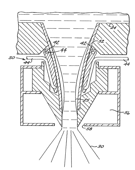
nozzle 26. A ~irst embodi~ent o~ such a nozzl~ ~6
is illustrated in Figures 2 and 3. The nozzle 26
include~ an el~ctrornagnetic ~ieldl piece 42 thalt
induce a pinc:hin~ field around the ~;tream 25 after
20 it em~rges from the ~30urce 24. l~e field pi~c~ 42
solid piece o~ metallic condluctor, ~uch a~;
copper 1 in th~ s2~pe oî an i~v~rted funnq~l wi~h the
narrow end upward~ The 1~ pieGe 42 i ~ cc~ol~d by
an int~gral cos: 1 ing 1 in~ 4 4 attac:hed to th~ f iL~ld
25 pi6~ce 42. Cc~ol~ng ~ay be ~upplied by an ato~Diæirlg
g~!l, when powd~r is the produc~, or by water from a
wa~er ss~urc:e. Optionally, a cer~ic tub~ ~9 can b~
placed ov6~r tbe ~trea~ 25, between the ~tr~a~n 25 and
the ~ield pi~ce 42, a~ a ~ail~afa protec'c1 on ln the
30 eve~t that spla~shinçl c)~ s'cre~ 2S oc:cur~. For
some applic~tis~n~;, re~ractory ~ater~al~, 8u;:h a~
tantal Lun, molybderlu~ and ltungsta~n ~y lbe pr~erred
when sur~ie~23rlt cooling i~ not pos~ibl~.
18 2~8
1 DV 10630
As shown in Figure 3, th ield piece 42 is
split radially at on~ lucation, with each side of
the fleld piece 42 b~ing joined to a bus bar 46.
The bus bars 46 communicate to a radio frequency
S (RFI power supply (not shown~ that produoes power at
a frequency o~ fro~ about 250 to ~bout 350 KHz or
high~r. The RF ~ignal in t~e ~ield piece 42 induces
a magnetic ~i~ld, indicat~d ~c:hematically as ~ield
line~ at nu~eral 48, that tends l:o pinc:h the 5~f r~am
7 o 25 radially inwardly. The higher th~ power applied,
the grea1:er the G'cr~ngth o~ the magnetic field 48,
an :1 the greater the inwardly directed constric:tive
forc:e applied to th~ strea~ 25. Th2 m~ç~n~1:io field
therefore can be used to restrii:t the ~ia~neter and
thence the flow rate o~ Dletal ~n th~ stream 25.
Arlother e~bodim~nt of thc~ nozzl~ i8 sh :swn in
Figure 4~ A nozzl~ 50 is a t'close coupled nozzlell
which c:ombin s the metal flow control function and
the zlto7llization ~unetion into a ~ingle unit, and ha~
se~veral d¢~ign vari2ltion~ rel~ti~re to th~ embodi3nent
of Figure~ 2 and 3. Th~ nozzl$a 50 ~nc:lu~es an
inwardly 'caper¢d ~ eve 52 Dlade o~ c~raDic ~aterial,
thro~lgh ~ h the ~etal ~tream 25 ~lows ~ro9~
6surce 240 Ov~rlying th~ ~:le~ve 52, a w~ter-cooled
induction p1ec:~ ~2 ~urround the ~;'cream 25. The
inductio~ pi~ce 42 is conical, with the larger end
oriented upwardly and i8 coole~d by an integral
c:oolirlg line 4d~, which circulat~s water, or
alt~nlat1v~1y, when avA~ labl~, ga~ fro~ ~n ato~izer.
Th¢ induction piec~ 42 i~ connected to a radio
~x~quency pow6~r ~ourc:e like tbat discus~ed
pxeviously . Appï ~cation C~f a radio ~r~ ncy ~i~al
to the induction pieee 42 induces ~Dagnetic ~ield~
~19--
13DV 10630
that pinch the str~am 25 inwardly. The pinchin~
~ield i~ typically suf~icierltly strong tha~ the
stream 2S is pushed inwardly aw~y fro~n contacting
the inn~r wall of t~e 51eeve 52. This pinching
S orc:e controls the stream diameter and flow rate in
a manner like that discus~ed previously.
A ga plenum 56 is csn~txucted integrally
wit:h the lower end of th~ noz21e 50 and the sleeve
52. Opening~ 58 from the! gas plenu~n 56 are located
to direct a f low of inert gas ( ~u~h as ars~on~ Prom a
ga~ ~ource (not shownj inwardly ~t an downward angle
to i~pirlge again~t the streaDI 25. The ga~ flow
atc~izes the stream 25 to for~ ~e spray 30.
The preferr~d nozzles discussed here ~ith
respQCt to Figur~; 2~4 hav~ th~ characteri~tic that
incre~sed pinching or c:on tric:t~.on s~:lE th~ Detal
~;tream is as:c:o~pli~hed by increa~ing tl~e RF power to
th~ elee:troD~agnetic f eld piece or coil in the
slozzle. ~echanically adjustable noæzles c:ould
equi~ale~tly be us;ed, but th~ir re~ponse to co~and
signals would li ~ely b~ ~slower than desir~d ~or the
applic:ation~; of int~re~
Th~ ~yst@~ 20 ~ay be operat~d in severzll ways
to achieve di~fererlt obj~c:tive~ during v~rious
p~a~es o~ 6y~t~m oper~t:ion. ~i~ure~; 5 and ~
~llu~trat~ two di~fer~nt control mode~. In each
f i~r~ hardwar~ components ar~ identis:al, but
th~ cc~ntrol mode~ are di~ferent. (ql12 no~zl~ -
arrangem~nt of Figur~ 2-3 has been us~d in Figures
3 0 5 snd 6 ~or illu;trativ~ purpo es, ~ut the noz~le
~rrangemeDt of Figure 4, or other nozzle~;, could be
u~ d.) Figur~ 5 illu~3trate8 ~ ~;itu~tio~a wh~r~in the
~ourc~æ 24 i~ operatin~ within nor~al steady state
2~8~8~
--2~--
13DV 10630
limits, while Figur~ 6 illustrates a situation
wh~r~in the sours:e 24 has fluctuated (or been
intentionally perturbed) outside oP normal s eady
st~ate limits. Figure ~ illustrates in l~lock diagram
form the interrelation of th~ two control modes.
Re~rring to Figure 5, th~ relative position
o~ the sprsy 30 and the ~ub~trate 32 is deter;llin~d
~rom ~ea~uremen~ of the position sensor~ 40 in th~
gaæ ring 28 or its actuatinçl sy~tem ( i~ a movable
gas ring i~ us~d) and th~ hold~r 34. These
m~a ~rem~nt~ are ~rovided t~ a co~troller l;D, whi~h
i~ typically a progra~aed ~ roprQcessoæ. Fr~ the
8IE!n~Or ~asureas~nt~ position o~ the ilDpact of
th¢ spray 30 against th~ su~stxat* 32 is ~ete~ ed -
by ~ conv~ntiora~l calculation within a fr~ of
re~renc~. Thu6, ~or th~ ex2~ discu~sed sarli~r,
it ~o~y be ~etermin~d wh~th~r th~ ~in part o~
~apr~Ly 30 i~ . ~riXing ~n innOE!~r portion o~ 3 bills~
n~ar its cent~rline~, or an out~r ps~ ari o~
blllst~ ar it~ pQriph~ry~ or ~o~ewher~ be~e~n th~
two extr~m~s. ~ ~o~abl~ ~le~ent~ are dri~en by
anoth~r portion o~ ~e ~y~t~, not ~hown, to c~ver
~o ~ntiro ~ur~oo s~ ubstr~t~ witA lth~ ~pr~yed
metz~l. Th8 po~ltlon me~ar~m6~ts Dl~y ~ tak~n ~ro
~otor sett~ng~ of tho dr~v~ ~y~t~m. Although not
~trlctly req~air2d, ~Lt ~8 prefarr~d to continuou~ly
~os~ltDr th~ dia~eter of th~ malt ~treal~3 25 using the
~e~ns~sr 313 and ~t~ telDp~ralture using ~@ sense~r 3~O
~ro~ the position o~ th~ ~pray 30 rel~tivo to
3~ th~ ~ubE3trat~ 3~ th~ required metal ~l~aw i~
dlQter~isl~d. q~ ~netal ~ w a~ a gunction ol~
po~iltion i~ typiaall~ ~etar9~in~ ~r~ t~ up
tr$~ *, irl ~ nu~r o~ t~t p~ce~ ~t~r2a~d
2 ~ 8 ~
--Zl--
13DV-1t)630
prior to production operation6, the macrostructures
and micro~tructure~ as a function of position
r25111ting from various metal flows are de'cerrnin~d.
Acceptable me~al f:Low limits as a ~unction of
s position ar~ thereby determined. I'c would, of
course, ~e pxePerable to be able to predict he
required met~l flow :Erom ther~al and ~na~s flow
mod~ls of the spraying operation. How~Yer~ at the
pr~sent ti~e such r~od~l~ are not ~uf f ici~ntly
sophisti~at:6!d to ~:se r~ d upon fully withola~
experimantal verif ~ cation~.
What~ver techni5~ue is used, the r~ul~ i~ a
~mapping~7 o~ re~ired m~tal flow in the stre.am 25 ~s
a function of rel~'civ~s po~ition o~ the spray and t21e
substrat~. In o~her e:alibr~tion and st~r~-up tes~s,
th~ power requir~d to the ns:~zzle 26 tcs adju~i'c streaD
dia~net~r in order tc~ achi~ve particular m~tal flows
is d~1:er~ined. Using the map o9` metal flow
require~nents and the cal ibxation b~tween ap~l ied
pow~r and metal 10w rate, the controller 60 ends a
command ~;igslal to an RF pswer supply 62, which ln
turn applies the coD~and~a pow~r level ~o the noxzle
26 .
Thus, a~ ~h~ spEay 3 0 is ~c:anned ac:ro~ tl~e
~urfac~ o th~ ~ub~trat~ 32, the ~2'cal ~low rate i~;
ad~u~ted upwardly or downwardly as appropriat~a for a
pred~ter~ine~ location 2:~eing imp~e:ted ~y the 6pray.
Gen~rally, tho~e areas of th~ ~ubstrate that hava
~he largest and ~ost exposed ~ur~ac~ are~ uch as
~he outer portions n~ar the periphery~ receive th~
highe~t ~et21 ~lo~ rate~. Tho~ ~nner portions that
ar~ more inter~al and natur~lly cool ~Dor~ slc3wly,
r~c~iv~ low~ar ~netal ~lo~ rates. ~h~ relakiv~ rzlte
-22-
13DV-10630
of movement of the ~pray and the substr~te are
adjusted responsive to the me~al flow rates to
achieve a uni~or~ huildup of metal acros~ the
surface of th~ subs~rat~.)
Another control mode is illustrated in Figure
6. Here, the source 24 is assumed to have varied
fro~ it~ normal steady stat~ operation for any of
several reasons, such as startup/shutdown, the~mal
variation~, reduced metal head, etc. The melt
sensor 36 provides a ~ignal to the controller 60 as
to the natur~ o~ th~ variation, and the controller
60 responds t~ avoid damage to the ~ystem and to
~aximize production o product of good quality.
For example, th~ melt lev~l in the ~ource 24
may b~ ~ensed by the ~elt level co~ponent of sensor
36 to be too low. To pE~Vent the source 24 from
being cQ~pletely drained of ~ol~en ~etal, which
w~uld pose a risk of damage to the component~ and
~ak~ 6taxtup difficult, the c~ntroller ~0 commands
the RF powd~r ~upply to increa~e the power to the
noz~le 26 to reduce the flow rat~ of the metal in
th~ s~reaM 250 Simultaneously, the controller ~0
c::or~zmd~ an increa~ad rate o~ adldi~ion o~ ~t~l ~o
the ~ource 24 ~rom a ~ead 64. The metal in the
source 24 1~ ther~ore conserved until th~ steady
~t~te acc~tabl~ op~rating li~its are regained, at
which time t~e ~yste~ revert~ to the control mode of
Figurs 54
Wh~n th~ Slow rate o~ molten ~etal in ~he
~tr~a~ 2S i~ changed responsive to the ~luctuation
in th~ ~ourcQ 2~, the character o~ thQ ~pr~y 30 also
chang~. In the example discus~d, the ~etal flow
rat~ i~ reduc~d, th~ gas-to~metal ~G/~) ratio o~ th~
--23--
13r)V-1063U
spray 30 increases, and 'che spray becomes cooler.
One possible control system response is to reduce
the flow rate G o~ atomization gas to the gas ring
2 8, to incr~ase the temperature of the spray 3 0 to
its n;: r~al range ~maintaining ~ constant G/M
ratio. ) . Consi~t~nt with a lower m~tal flow rate M,
the bill~t wi1:hdrawal rat~ may be slowèd to maintain
a consistent build up pr~f ile .
Another colltrol system respons~ is to change
the loc~tion of th~ depos~'cion in accordanc~ with
the previously det~rmir3ed ~apping o~ G/M and
location on th~ bill2t. Thus, a c:ooler spray is
preferably deposited on th~ inner portions of the
slabstr~te rather than th~ o~ter portion~;. To the
extent that the cooler ~pray i~ deposited on the
outer por'cions, ~h~ f inal product prc~uced during
the fluc:tuation of the scsurce 24 may nol: b~
accep'ca~le. To ~ainimize" and d~sirably prevent,
production of unacc:eptable produc:t during ~ource
fluctuations, the cor~troller 60 command~ the gas
ring 28 ( if movabl~ and holder 34 to po5ition the
~pray 3û relativ~ to the ub~trat~ 32 ~o tha.t Dlore
o~ the spr~y 30 ia directe~ aga~n~t th~ inne;r
~portlon~ of the~ tra~e than the out~r portions of
the substrate a~ long as the low Dletal flow
condi tion per~;ist~: duri~g t~e ~luctuatiQn o~
sour~ 24. Th~ inner portions 1:herefore build up
preferentially to the olater portions. This un~ven
buildup carmot continue in~finitely, an~ eventually
3 0 th~r~ wlll be ~ pre~erentia~ d~po~ition on the outer
porltion~; to ::r~te an e t~n t~ l~e~s o th~ ~epo~it
o~ mQtal, It ~ ~xp~c:ted ~hat und~r ~o~;t conditio~s
~h~ ontrol ~y6t~ Or the~ in~ntion ~ill r~turn th~
~01 8~
--24--
13DV-10630
deposition to its noxTnal limi'cs in a su~fici~ntly
s~lort time ~hat the unev~n deposition is tolerated.
Alternatively, he two con1:rol approaches may be
com~ined, with the G/M ratio adjust~d in conjunctior
5 with lc: c:ation of the d~position,
Thus, as indicat@d in Figur~ 7 ~or 'ch~
preferred approacb,, in nor~al oper~tion the 1~w oP
metal is controll~d respon~iv~ to the positiorl of
depo~ition on the substra~, while und6~r abnormal
10 ~source ope~ration th~ flow o ~netal is c:ontrolied
responsiv~ to the source onditiQn~;~ In the latt~r
ca~e:, cont.rollabl~ ~ource charac:teri~;tic~; ~ue:h as
power input or ga5 iElow, or 'che po~ition of
d¢positiorl, ~re c:ontrolledl respon~ive to the metal
15 ~low rate.
It will be appreciated that many other
control situations ~ay occ:ur, and the 5y~;t6~B
reE;porlse ia within th~ 3~cop~ of the cc~ntroll~r
function~ ~ust ~liscuE;s~d. FOr exampl~, a var~ation
~o in strea~ ~emperature a~ 2easured by the sensor 39
provoke~ a respon~a that will bring the te~p~rature
back to the s~Qsdy s~ato value, such as modifyirlg
th~ heat input to t~g: ~elt îroD~ heat ~ourc~s 66
~typically ~ plas~ torch) t and/or temporarll~
25 ~csdifyin~ th~ flo~ r~te o~ ato3llizing gaa~.
T~e present approach therefore u~:e~; a
variabl~ metzl flow nozzle and ins;tna~ented Dletal
deposiltion apparatus to achiev~ unifona,
high-qual ity product ov~r the entire æu~str~t~ and
30 in th~ f~nal article. It increases th~ tol~r~nce o~
the deposltion pro e~;~ tc~ fluctuzlt~ons that can
occur ~n the melt~l ~ource, preverltin~ dz~ag~ to 'che
componen~ ~ns~ produG~ng a good produc:t in 8pit~ o~E
- ~gQ~8~
--25~
13DV-10630
the fluctuation~. These beneficial results are
accomplished in part 'chrough control v~ the spray of
molten metal droplets. This invention has been
described in connection with speci~ic e~odimerlts
S and exaJnples~ However, it will be readily
recognized by those skilled in th~ art the various
modifications and variations of which the present
inventlon i5 capable without departing ~rom its
scope ~s represent~d by t~e ~ppended c:lai~ns.