Note: Descriptions are shown in the official language in which they were submitted.
2~8~257
1 56,299
SOLID OXIDE FUEL CELL GENERATOR
GOVERNMENT CONT~ACT
~his invention was made in the performance of
Contract DE-AC2180ET-17089 with the United States Depart-
ment of Energy.
BACKGROUND OF THE INVENTION
This invention relates to a solid oxide fuel
cell generator and, more particularly, to a generator
having an array of closely spaced, tubular, axially
elongated fuel cells for electrochemically reacting a fuel
gas with an oxidizing gas.
Solid oxide fuel cell generators are employed to
convert the chemical energy of a fuel gas such as natural
gas into electrical energy. Typically, generators contain
an array of literally hundreds or thousands of fuel cells
which must be electrically connected in series and in
parallel to produce the desired energy because each fuel
cell develops a limited amount of energy at about 0.6 to
1.0 volt. For example, a state-of-the-art fuel cell
having an active length of about 30-50 cm will produce
approximately 20-40 watts. The fuel gas and an oxidizing
gas, which is usually an oxygen-containing gas such as
air, electrochemically react across the electrolyte
boundary of the fuel cells at about 1000C and produce
carbon dioxide and water vapor.
State-of-the-art generators are disclosed by
U.S. Patent Nos. 4,898,792; 4,87~,678; 4,728,584 and
4,395,468. These patents generally disclose solid oxide
fuel cell generators having arrays of tubular, elongated
.. . . , . . . i .
. . . , -, . ,; : .;. . . - . : - ~ .
- . : :: :. ., i: .; ,, . - : .
', ." . ! ~ ` , ,. : : .,
' ' . .' '" '~,' ~ ' . .' :. .. ,'
2~80257
2 56,299
fuel cells comprised of electrochemical cells supported on
peripheral surfaces of hollow tubes which extend through a
generator chamber. ~hese generators generally employ
designs wherein an oxidizing gas (typically air) is
introduced into hollow support tubes via internal,
concentric, injector tubes which extend at least about
half the length of the support tubes. The oxidizing gas
flows toward the opposite ends of the hollow tubes, exits
the injector tubes, reverses direction and flows back
through the annulus between the support tubes and the
injector tubes. This arrangement is designed to preheat
the oxidant gas up to the reaction temperature and also to
remove the excess heat generated by the electrochemical
reaction in order to maintain the desired operating
temperatures in the generator chamber. Typically (where
the oxidant gas is air), up to 4-8 times the stoichio-
metrical amount of the oxidant gas needed to react with
the fuel gas is fed into the tubes in order to maintain
the nominal reaction temperature and the desired tempera-
ture profile in the generator.
Efficient operation of the prior art generatorsunder low power, normal power and high power conditions is
limited by many process variables, including the pressure
drop of the gases flowing through the injector tubes and
in the annular spaces around the injector tubes. The gas
flow pressure drop through the tubes and the associated
end effects tend to restrict high gas flow during high
power conditions for a given generator design. In
addition, temperature profiles across generators may vary
because the fuel cells located at the peripheries of the
generator housings tend to radiate substantial amounts of
heat to the housings, which can be a substantial percen-
tage of the excess heat generated, particularly during
; low electrical power operations. Typically (where air
flows through the tubes of the fuel cells and fuel gases
flow through the plena containing the fuel cells), the
nominal reaction temperatures and thermal profiles are
maintained by feeding a certain amount of excess oxidant
. :~
: ~ ' : ., ` .
: :: ~::
'':' . , .. ::
20802~7
3 56,299
gas to the interior fuel cells in an array and simul-
taneously feeding substantially less excess oxidant gas to
the peripheral fuel cells because of the lower excess heat
remaining after losing heat to the housings. Undesirably,
5this requires additional air controllers to regulate the
air flow in the peripheral cells separately from the air
flow to the interior cells.
Present state-of-the-art generators employ
arrays of fuel cells having electrochemically active
10lengths of up to about 30-50 centimeters. The installa-
tion of hundreds and even thousands of long injector tubes
in such fuel cells is both costly and very difficult to
accomplish in commercial scale generators. Furthermore,
the art anticipates that future generators will employ
15even longer fuel cells having active lengths of up to 100
centimeters or more in order to reduce the required number
of fuel cells in a generator.
Accordingly, the art is searching for new
generator designs which are less costly and difficult to
20assemble than are present designs, and yet are more
efficient.
SU~RY OF THE INVENTION
It is an object of the present invention to
provide an improved solid oxide fu^l cell generator
25arrangement which is structurally le&s complicated than
are present generator designs. It is another object of
the present invention to provide a generator design which
will efficiently operate over a wide range of power
conditions. Another object is to permit the use of longer
30cells; e.g., cells up to 100-200 cm or more, with lower
pressure drop.
With these objects in view, the present inven-
tion resides in a solid oxide fuel cell generator for
electrochemically reacting a fuel gas with an oxidizing
35gas. A generator embodying the present invention general-
ly has a housing containing two spaced apart tubesheets
; and at least two spaced apart, intermediate barrier walls
between and spaced from the tubesheets. The housing and
.~
.
. . . ~:
, ~ .
2~02~7
4 56,299
the barrier walls define a generator chamber spaced from
the tubesheets. An array of spac~d apart fuel cells
extend through the generator chamber and engage the
tubesheets. Each fuel cell comprises a hollow tube having
a peripheral surface and an axial length which extends
between two open tube ends engaging the tubesheets. Each
fuel cell also has an electrochemical cell superposed on
the peripheral surface of the tube in the generator
chamber. An electrochemical cell generally comprises a
solid oxide electrolyte and a contiguous electrical
interconnector with the solid oxide electrolyte concentri-
cally disposed between a fuel electrode and an oxidant
electrode. The hollow tube supporting the electrochemical
cell may also function as an electrode in some generator
designs, although it is generally less costly to support
both fuel and oxidant electrodes on the peripheral surface
of another tube.
In one generator design embodying the present
invention, the electrochemical cells axially extend at
least about 50 centimeters (cm) and for less than about
60% of the total fuel cell length. In another preferred
design, the active length of each fuel cell is at least
about 100 cm. Such a design provides low total gas flow
pressure drops in the fuel cells and at their ends and
also provides a large heat transfer area for preheating
and later cooling the gases as they flow through the fuel
cells.
In a preferred embodiment of the present
invention, the fuel cells seallessly engage the tubesheets
whereby a small amount of gas lea~age is permitted between
the fuel cells and the tubesheets. Sealless generators
have intermediate buffer chambers disposed between the
generator chamber and the tubesheets. The buffer chambers
and (preferably) gas pumping means such as an ejector and
the like in gas flow communication with the buffer
chambers mitigate gas leakage from the generator chamber
and through the tubesheets.
.
20802~7
5 56,299
In the above sealless generator arrangement, the
generator chamber will inherently be at a higher pressure
than the buffer chambers during the operation of the
generator. Therefore, the leakage paths will be such that
5rich fuel will be permitted to leak out of the generator
chamber. This generator design is arranged to entrain
those leaked rich fuel gases into a depleted fuel gas
stream, thereby preventing spontaneous combustion with the
oxidant gas, and is recirculated back into the generator
10fuel supply. Thus, the fuel management and efficiency and
thermal management is enhanced. In a similar manner, the
generator arrangement provides a depleted fuel chamber
adjacent to and at a higher pressure than the oxidant gas
chamber at each end of the fuel cell. This also assures
15that the depleted fuel leaks around the fuel cells and
through the flow holes in the tubesheet into the oxidant
gas chamber where intended remaining combustion may occur.
The buffer zone arrangement thus prevents the oxidant gas
from leaking directly into the generator chambers contain-
20ing the rich fuel.
pESCRIPTION OF THE DRAWINGS
The invention will become more readily apparent
from the following description of two preferred embodi-
ments thereof shown,by way of example only, in the
25accompanying drawings, wherein:
Figure 1 schematically shows a first solid oxide
fuel cell generator embodying the present invention;
Figure 2 schematically shows a fuel cell which
may be employed in the generator of Figure 1;
30Figure 3 schematically shows a cross-sectional
view of the fuel cell of Figure 2, generally taken along
section line 3-3; and
Figure 4 schematically shows a second solid
; oxide fuel cell generator embodying the present invention.
35DESCRIPTION OF THE PREFERRED EMBODIMENTS
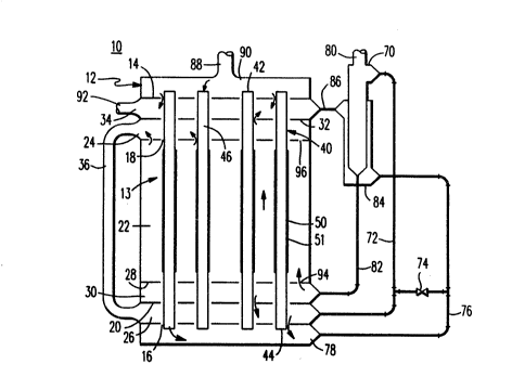
Referring initially to Figures 1-3, Figure 1
generally shows a solid oxide fuel cell generator 10
comprising a housing 12 containing a vertically oriented
:- .
. ~
- : ~
~ '' . , ~, . ... ..
2~80257
6 56,299
fuel cell array 13. Alternatively, the fuel cell array 13
may be horizontally or otherwise oriented to meet the
particular process needs. The generator 10 of Figure 1 is
particularly useful for electrochemically reacting natural
5gas or another fuel gas with oxygen from air to produce
electrical energy, although it may be employed with other
process or waste fuel-containing gases and oxidant gases.
Preferably, the gases do not contain substantial amounts
of contaminating gases or entrained particles which may
10foul the generators. For purposes of convenient discus-
sion, the invention will be described in the context of ~
generator wherein the oxidant gas (air) flows through the
fuel cells and the fuel gas flows through the plena
containing the fuel cells. However, the gas flows may be
15reversed in other embodiments of the present invention so
that the fuel gas flows through the fuel cells.
The generator 10 of Figure 1 has first and
second tube sheets 14, 16 spaced apart in the housing 12
with at least two spaced apart intermediate barrier walls
2018, 20 disposed between them. The intermediate barrier
walls 18, 20 define a generator chamber 22. The inter-
mediate barrier walls 18, 20 also partially define
adjacent (to the generator chamber 22) buffer chambers 24,
26 disposed between the generator chamber 22 and the
25tubesheets 14, 16 respectively. The tubesheets 14, 16 may
be comprised of stainless steel or Inconel and the barrier
walls may be comprised of zirconia or other material
having suitable high temperature physical properties. As
is shown in Figure 1, an additional barrier wall 28 may be
30employed in the generator chamber 22 to provide a dis-
tributor chamber 30 for distributing feed fuel gases
across the fuel cell array 13 (as will be discussed below)
and an additional barrier wall 32 may be employed adjacent
one tubesheet 14 to provide a preheating chamber 34 to
35preheat the air flowing through the fuel cell array 13 (as
will be discussed below). As is shown in Figure 1, the
buffer chambers 24, 26 are preferably interconnected by a
: .
.:
2~0257
7 56,299
duct 36 which may be external (as shown) or internal (not
shown) of the fuel cell array 13.
The array 13 generally comprises hollow,
cylindrical fuel cells 40 axially extending between the
tubesheets 14, 16. Each fuel cell 40 has an open end 42
engaged with the first tubesheet 14 and an open end 44
engaged with the second tubesheet 16. The fuel cells 40
may have a supporting porous calcia-stabilized zirconia
tubular structure 46 having a peripheral surface 48 and an
axial length 50. A suitable tube 46 may have a thickness
of about . 5-5 mm and a diameter of about 1 c~. In an
alternative embodiment (not shown), the fuel cell is
supported by one of the electrodes so that a separate
tubular support is not employed. Preferably, the fuel
cells 40 seallessly engage the tubesheets 14, 16 such that
gases are permitted to leak around the tubes and through
the tubesheets 14, 16 (as well as through the barrier
walls 18, 20, 28 and 32). Generally speaking, however,
such gas leakage is undesirable and therefore the operat-
ing conditions in the generator (and particularly the
pressure differential across the tube sheets 14, 16) are
preferably maintained so as to reduce the leakage in the
generator 10 to the lowest practical levels.
As is best seen in Figures 2 and 3, each fuel
cell 40 has an electrochemical cell 51 superposed on the
peripheral surface 48 of the tubular structure 46. The
tubular structure 46 mechanically supports the electro-
chemical cell 51 in the generator chamber 22. The
electrochemical cell 51 generally has concentric, porous
air and fuel electrodes 52 and 54 separated by a nonporous
solid oxide electrolyte 56. Where air is the oxidizing
gas and flows through the support structure 46 from open
end 42 to open end 44, the oxygen in the air generally
diffuses outwardly through the porous zirconia of the
support structure 46 and the porous air electrode 52. The
oxygen then dissociates to an ionic form and the ions
diffuse through the solid oxide electrolyte and react with
-:
,;, ,
:
2~02~7
8 56,299
the fuel at the fuel electrode 54 to form water vapor and
carbon dioxide.
The air electrode 52 preferably has a thickness
of at least about 0.5-2 mm and comprises a composite of
doped or undoped oxides or mixture. of oxides of the
perovskite family, rare earths oxides, indium oxide, and
oxides of cobalt, nickel, copper, iron, chromium and
manganese. The fuel electrode 54 preferably has a
thickness of at least about 100 ~m and comprises a nickel-
zirconia cermet or other suitable material. The solidoxide electrolyte 56 preferably has a thickness of at
least about 20 ~m and comprises yttria stabilized zirconia
or other suitable ceramic material.
A nonporous, electrically conducting intercon-
nector 58 radially extends from the air electrode 52 forinterconnecting the fuel cell 40 and adjacent fuel cells
(not shown) via nickel fiber felts or the like (not
shown). The interconnector 58 preferably has a thickness
of about 10-100 ~m and comprises a calcium, strontium or
magnesium oxide doped lanthanum chromite film or other
suitable ceramic material.
A preferred fuel cell 40 has a .7 mm thick
porous tube 46, a 2 mm air electrode 5~, a 40 ~m solid
electrolyte, a 100 ~m fuel electrode and a 40 ~m inter-
connector 56.
Preferably, the electrochemical cells 51 axiallyextend at least about 50 cm in length in order to generate
more power per fuel cell than do present cells, and also
extend less than about 60% of the total length of the
fuel cells 40 in order to provide a substantial heat
transfer area between the air and the fuel gases.
Advantageously, concentric injector tubes need not be
provided to preheat the gases or to cool the fuel cells
;i 40. In other embodiments of the invention, short injector
tubes (not shown~ may be employed to inject tubeside gases
` into the open ends 42 of the cells 40, although such
arrangements are not preferred where the cell lengths are
less than about 100 cm.
.
.
20~02~7
9 56,299
An ejector 70 or other gas pumping means may be
employed to pump the gases from the intermediate buffer
chambers 24 and 26 so that leaking fuel gas and air are
buffered with spent gases. Importantly, the leakage
across the tubesheet 16 is mitigated by the ejector 70.
The pressure differential across the tubesheet 16 is
generally mainta.ined by pumping the gas in the inter-
mediate chamber 26 through a pipe 72 into the suction of
the eductor 70. A back pressure control valve 74 between
the suction pipe 72 and a tubeside exhaust pipe 76 from a
tubeside exhaust chamber 78 may be employed to more
effectively control the pressure differential across the
tubesheet 16. The ejector 70 shown employs feed fuel gas
in supply pipe 80 to pump the spent fuel gas from the
buffer chambers 24, 26. Advantageously, the educted gases
may be reformed in the eductor 70 and reintroduced through
pipe 82 into the fuel gas distribution chamber 30, which
distributes the gas throughout the housing 12. The fuel
gas in the ejector 70 is preferably heated (for reforming
the spent fuel) by the exhaust air which flows from the
exhaust pipe 76 through an ejector jacket 84 and then
through a pipe 86 into the preheat chamber 34 for preheat-
ing the air. The fuel gas is also preheated in the
intermediate distributor chamber 30 by the exhausted air.
In other embodiments, the exhausted gases may not be
reformed.
In operation, the generator 10 is continuously
supplied with air from a supply pipe 88 which flows into
an air supply chamber 90. The air flows into the ends 42
of the tubes 40 and into the preheat chamber 34 where it
is preheated by the combusting spent gases, which are a
mixture of the exhausted air from pipe 86 and spent fuel
gas leaking through the intermediate barrier wall 32 and
also supply air leaking through the tubesheet 14. The
preheated air within the tubes 40 is further heated by
spent fuel gases in the buffer chamber 24 and flows into
the generator chamber 22 where it electrochemically reacts
at cells 51. Exhausted air then flows through the tubes
;.
.
2~8~257
10 56,299
46 into the intermediate distributor chamber 30 (where the
exhausted air preheats the feed fuel gas) and then into
the intermediate buffer chamber 26 before flowing into an
exhaust chamber 78. ~he exhausted air then flows through
pipe 76, ejector jacket 84 and pipe 86 and into the
preheat chamber 34 where it is combusted with the spent
fuel gas to preheat the supply air. The combusted gases
are then discharged through outlet piping 92.
While the air is continuously fed to the air
supply chamber 90, the fuel gas is introduced into the
intermediate distributor chamber 30 (which is part of the
generated cham~er 22) where it is distributed across the
cell array 13 and preheated. The gas then flows through
orifices 94 in the intermediate barrier 28 into the
generator chamber 22 proper, where the fuel gas electro-
chemically reacts at the cells 51. In other embodiments
of the invention, the fuel gas may diffuse through a
porous intermediate barrier wall (not shown) rather than
flowing through the orifices 94 or be distributed within
thermally insulated piping manifolds. In addition, the
fuel is permitted to leak between the support tubes 46 and
the barrier walls 18, 20, 28 and 32. The generator
chamber 22 may also contain baffles (not shown) and the
like to direct the fuel gas through the chamber 22. Spent
fuel gas then flows from the generator chamber 22 through
orifices 96 in the intermediate barrier wall 18 and into
the intermediate buffer chamber 24 which is connected by
duct 36 to the intermediate buffer chamber 26 adjacent the
tubesheet 16. A portion of the gas in the intermediate
buf~er chamber 24 leaks through the intermediate barrier
wall 32 into the adjacent intermediate preheat chamber 34
where the gas is combusted to preheat the supply air. The
balance of the gas in the intermediate chamber 24 is
pumped into the intermediate chamber 26 to buffer the fuel
gas leakage into the air at the tubesheet 16. It should
be noted that spent fuel gas in the buffer chamber 24, 26
leak away from the generator chamber 22. Advantageously,
the ejector 70 maintains a pressure differential across
.
. .
2~2S7
11 56,299
the tubesheet 16 so that leakage can be maintained and
controlled.
Figure 4 shows a second embodiment of the
present invention where a generator 102 has an array 104
5of interior fuel cells 106 arranged in serial gas flow
with peripheral shortened fuel cells 108 which are
adjacent to the housing 112. Advantageously, such an
arrangement introduces hot tubeside gases to the peri-
pheral cells 108 under any transient or steady state
10operating conditions including high power conditions.
Thus additional air flow controllers are not required to
separately control the peripheral fuel cells 108 to
compensate for heat losses to the housing 110 due to
radiation. In addition, the exhausted air may be inter-
15nally introduced into a preheater such as intermediate
combustion chamber 112 with little pressure drop.
The generator 102 has first and second tube-
sheets 120, 122 spaced apart in the housing llo from
intermediate barrier walls 126 and 128. This structure
20generally defines an air supply chamber 132, the inter-
mediate combustion chamber 112 for preheating the air, an
intermedia~e buffer chamber 136 connected by duct 138 to
an intermediate buffer chamber 140 for buffering gas
leakage from a generator chamber 142, an appurtenant
25intermediate distribution chamber 144 for preheating and
distributing fuel gas before it flows through the genera-
tor chamber 142, and an air exhaust chamber 146. The
spent gases in chambers 136 and 140 are pumped through a
suction pipe 150 into an ejector 152 or other gas pumping
30means. As is shown, the spent gases may be reformed and
returned to the intermediate distributor chamber 144
through pipe 156 along with the feed fuel gas. The feed
and reformed fuel gases are preheated in the intermediate
distribution chamber 144 and then flow through orifices
35158 in a barrier wall 160 and into the generator chamber
142 where they react at the fuel cells 106 and 108. The
spent gases then flow through orifices 162 in the barrier
wall 126 into the intermediate buffer chamber 136, and a
. :' ' ' ;' ; ' ~ . '
,: . : ,,
: - ,.,,~ :'
. .' . '
20802~7
12 56,299
portion leaks through a tubesheet 164 into the inter-
mediate combustion chamber 112 where they are combusted
with the exhausted air to preheat the feed air gas. The
combusted gases in the intermediate combustion chamber 112
flow from the generator 102 through an outlet pipe 170. A
portion of the combusted gases flow through a branch pipe
172 and into a heating jacket 174 on the ejector 154 for
reforming the spent fuel and then out through a pipe 176.
A control valve 180 in a pipe 182 extending between the
suction pipe 150 and the outlet pipe 170 may be employed
to mitigate gas leakage in the intermediate buffer chamber
140 and pressure differential around the adjacent tube-
sheet 122.
In the generator 102 of Figure 4, the feed air
gas flows through an inlet 164 into the air supply chamber
132. The air flows through the interior cells 106 and
into the exhaust chamber 146. The oxidant gases in the
air exhaust chamber 146 then flow into the peripheral
tubes. The hot air gas then flows in the reverse direc-
tion in the peripheral cells 108 and into the intermediate
combustion chamber 112 where it combusts with the leaking
spent fuel gas to preheat the feed air. Thus the
peripheral tubes will always be supplied with preheated
air, even at very low power levels when the gas flow rates
are low, which maintains the generator peripheral cells
108 at a high temperature even when the excess thermal
power level is low. In a preferred embodiment of the
present invention, a generator 102 has an array 104 of
2016 fuel cells, with the peripheral three rows of cells
108 serially arranged downstream of the interior cells 106
so that about 25% of the tubes are serially downstream of
about 75% of the tubes.
Generators embodying the present invention are
structurally more simple than are the currently designed
generators because the long concentric gas injector tubes
are not required and because close tolerances between the
support tubes and the tubesheets and barrier walls are
not necessary. In addition, generators arranged with the
.
, ., :, .
-- - , ~ , :
' ' '~ ' ~ ~ .,
2~80257
13 56,299
peripheral fuel cells serially downstream of the interior
fuel cells do not need additional flow controllers to
separately control gas flow through the peripheral cells
to compensate for thermal radiation losses.
While presently preferred embodiments of the
present invention have been shown and described as well as
certain objects, advantages and details thereof, it is to
be distinctly understood that the invention is not limited
thereto but may be otherwise variously embodied within the
.scape of the following claims.
; ~
, . . . ~
- . ~ .' ~