Note: Descriptions are shown in the official language in which they were submitted.
WO91/15107PCT/US91/02326
- 1 - 2~ '57
SOLAR POWE~ED MO~ER
This is a continuation in-part of United
States Serial No. 506,903 filed April l0, l990.
: 5
Field of_the Invention
This invention relates to power mowers and
more particularly to power mowers powered by
electrical motors.
Backqround o~ the Invention
Present day power mowers can be powered
either by a 4-cycle gasoline engino or a 2-cycle
gasoline engine for providing powar to drive a
cutting blad~ of either ~he rotary or r~el type.
~i Other power mowers have ~n electric motor that drives
l a cutt~ng blade Or eithar typa the rotary or reel
; 20 typ-. Such alectric motor power~d mowers have the
power supply provided to the motor through an
extensi~le cord which connocts to a standard
domestic power supply.
.. . .
.. : . .
: '
.~ ~
, ~ ' .
..... ... , ~ .
-,:: : . ~ ,
WO91/15107 PCT/US91/02326
2~3~7
The use of gasoline engine constitutes a
substantial source of air pollution which in time
could become regulated by the E.P.A. as are larger
engines for powering automobiles and other motor
vehicles. The alternative to such gasoline engines
is a cord type electric motor driven mower. Such
mowers, however, are not as mobile as gasoline engine
mowers in that they must be connected to a power
supply by a cord during their operation. Such power
cords are susceptible to being cut by the blade to
produce exposed power leads. Additionally, while not
a direct polluter, such electric powered mowers are
powered from a central power plant which, if fossil
fuel fired, can be a significant source of pollutants
unl~ss suitable waste recovery sys,ams are
incorporated in the central system.
Sum~arY of the Invention
Accordingly, a ~eature o~ the present
invention is to provide a pow~red mower with a power
supply that has little or no emis~ions therefrom.
.
. . .
.
i~ ' . ' ' , : '
: ~ , . - ' .: '. :
. ~ - - . : . . :
W091/15107 PCT/US91~02326
; - 3 -
2 ~ 7
Another feature of the present inventio~ is
to provide an electrically powered mower with a power
supply that does not require a cord for supplying
electrical power thereto
Another feature of the present invention is
to provide a powered mower with a rotary blade driven
by an electrical drive motor which is connected to a
cordless source of power including a primary power
source for providing electrical power to the drive
motor and further including a secondary source of ~-
power that generates power solely on exposure to
light energy
.
Still another faature is .o provide powered
mowers of the type set ~orth in the preceding objects
wherein the source o~ pow-r includes a cordless power
i supply or an ~lectric drive motor located on the
upper sur~ace of a protective houslng; the cordless
power supply including a primary source o~ electrical
power for driving the electric motor and further
including a secondary source o~ electrical power for
charging th~ primary source of ~l~ctrical power as
power is supplied from said primary source of
lectrical power to the electric drive motor~
i: ~
'
'~
.
WO91/15107 PCT/US91/02326
20~3~7 4 _
Yet another object of the present invention
is to provide an electric power mower having a solar
panel with solar cells thereon for charging onboard
batteries which eupply primary power to the electric
motor of the electrically powered mower so as to
eliminatP the need for a power cord
Still another object o~ the present
invention is to provide a power mower with a rotary
blade driven by an electric motor having a primary
source of power de~ined by rechargeable batteries
mounted on the mower and including a secondary source
of power mountad on the mower for charging the
rechargeable batteries as they supply power to the
drive motor
Another ob~ct o~ the pres-nt invention is
to provide pow-r mower~ o~ th- pr-ceding ob~ect
wherein the secondary power sourcQ i8 a solar panel
located in ov-rlying relation~hip to th2 drive motor
~o a~ to intercept sunlight from different directions
; as the ~ower is driven in a cutting pattern across a
lawn surf~ce
: . ~ , : . . . . . : . .
- - . -
. - ~. - . -
WO9l/lSI07 PCT/US9l/02326
5 ~ 2~0~7
Yet another object of the present invention
is to provide a solar powered mower having the
supplemental power source for~ed as separate solar
panels or solar cells formed on the sides and front
of the mower deck or blade housing and~or the handles
thereof
St$11 another object of the present
invention is to provide a solar powered mower having
the supplemental power source formed as separate
solar panel or solar cells formed as covers on a
grass catcher connected to the mower to collect grass
cut by th- cutting blades of the power ~ower
: ,
Still ano~her ob~ect o~ the present
' invention i~ to provide a so}ar powered mower which
includes a rider platform th-r-on ~nd wherein ~he
solar power pan-ls for an lec~ric drive motor are
~orm-d cov-r~ over thQ front end of thQ solar powered
mow-r
".: ' ''
Still another featur~ of the present
invention i8 to provide such a powerad mower wherein
th~ solar panels or solar cells are mounted on
outrigger panels which are extendable from the main
housing of the power mower during U~Q for greatest
~,
...
~ ~ .
: , , ~ . -
. . . .
, . .
:~ . - . , . : .
.. , . ~ . . ~ . : . ..
,
W091/15107 PCT/US91/02326
2~8~3~7 - 6 - ` .
sun exposure but which are retractable to derine a
compact storage configuration when the mower is not
in use.
Still another object of the present
invention is to provide a power mower with a solar
power source including a shelter for the power mower
and wherein the solar power source includes solar
panels on the shelter to charge batteries onboard the
power mower in conjunction with solar panels mounted
on the power mower.
Y~t ano~her ob~ect of tha prQsent invention
is to provida ~ ~olar powered mower including a solar
: 15 panel or solar cQll ha~ing output t~rminals and a
connection circuit to the po~itiv~ and negative
terminals o~ a battery mounted on th~ power ~ower for
pow~ring ~ driv~ ~otor and wher~in the connection
circuit includ-~ a capacitor which is charg~d by the
solar pan~l~ when the panels arQ exposQd to sun light
and whlch is opexat~ve when th~ pAnels are not
expo~ed to sun to provide supplomental ~attery
charging current and wherein the connection circuit
. ~urther includes a diode to protQct the ~olar panel
.. .
~ .
'~
. ..
~, . .. . . . . .-
WO91/~5107 PCT/US9t/02326
2~3~7
or solar cell from bac~flow of current from the
battery to the solar panel or solar cells when the
panels are not producing a charging current.
Still another object of the present
invention is to provide a solar powered mower of the
- type set forth in the preceding objects and features
wherein the mower includes a safety switch in its
electrical control circuit in the form of a attitude
responsive switch on the mower that will disconnect
the drive motor from the power sources when the mower
is tilted or tipped through an angle which will
expose the cutting blades to a user.
.
Yet another o~jQct of th~ pre~e~t invention
is to provide such a sarety circuit o~ the preceding
ob~-ct wh~rein the swltch is a mercury æwitch which
is oriented to interrupt th~ power æupply to the
electric drive ~otor wh~n the mower is tipped.
Still another ob~ct o~ th~ present
invention is to provide the solar panels as flexible
amorphouæ silicon sprayed or dipped on surfaces
associated with the mowar thereby allowing the full
surface ar~a o~ a mower deck, a mower chassis or a
bagging unit to become a generator o~ solar power.
~' :
- , ~
- , , ,, . - ::' :
'~ - ' :
' - ' ,: .
wo9l~lslo7 PCT/US91/02326
_ ~ _
2Q~a3~
These and other features, advantages and
objects of the present invention will become more
apparent in view of the accompanying written
description of a preferred embodiment of the
invention when taken in conjunction with the appended
drawings wherein:
Brief DescriDtion of the Drawinqs
'
FIG. 1 is a side view of a power mower of
the present invention;
; .
FIG~ 2 is an enlarged top elevational view
of the power mower of FIGo 1 with a solar panel
: 15 thereof removed;
,: - .' .
:! . .
FIG~ 3 is a top elevational view of the
solar panel of the present invention:
FIG~ 4 is a side elevational view of the
~olar panel of FIG~ 3; and
~; FIG. 5 is a top elevational view of another
embodiment of a solar panel ~or u~e with the present
2S invention.
.
.. . .
~. . .
I ~ -
.
~, : . . . , . : :.:- - . : .- -
WO91/15107 PCTtUS91/02326
- 9 - 2~ 7
- FIG. 6 is a persp~ctive view of another
embodiment of the invention with solar panels located
on the front, sides and top of the ~ower deck as well
- as on the handles thereof;
FIG. 7 is a sectional view taken along the
line 7-7 of FIG. 6 looking in the direction of the
. arrows;
FIG. 8 is a perspective view of still
another embodiment of the invention which includes a
pow~r mower having a grass catcher with solar panels
~ forming the exterior surfaces thereo~;
-~ lS FIG. 9 is a perspective view of another
embodiment of the invention baving solar panels or
solar cells mounted on outriggerQ connected to the
housing o~ a power mower driven by a battRry powered
electxic motor and wherein control circuits connect
th- solar panQls or solar c-lls on the outriggers to
the batt-ry ~or charging it during us~;
~,. j . .
FIG. lO is a perspective view o~ a rider
mower including a ~orward co~partment with its roof
formed with outer solar panels thereon:
, ~.,
,
.
~ .
. - ~ .- . . :
-, . ~ .
. .
WOgl/15107 PCT/US91/02326
-- 10 -- _
2 ~ 7
FIG. lOA is a front elevational view of an
electric motor powered rider mower including a flat
protective roof having solar panels thereon for
charging a storage battery on the mower:
FIGo lOB is a side elevational view of an
electric motor powered rider mower including a sloped
roof cover having such solar panels thereon;
FIG~ 11 is a perspective view of another
rider mower including a rider seat ~ounted as a
pedestal ~orward of a mower platfor3 and wherein
solar panels ar~ provided on the sidas and front of
the ~ower platform and al80 on the top o~ a rear
i5 20unted gra~s coliector;
FIG. 12 is a perspective view of a solar
garage ~or housing a solar chargad slectric ~otor
drivan po~er mower including a roof panel defining a
solar pan-l or solar cell~ to suppl-ment the battery
: charging o~ the ~olar panels mounted directly on the
solar power mower:
'' ' .
FIG. 12~ is a flat roo~ad version of the
solar garag~ Or FIG. 12:
.
~ :.:
. .
- . . .. .
WO9l/15107 PCT/US91/02326
- 11 - 2~3~
FIG. 12B is another embodiment of the selar
garage:
FIG. 13 is a cir~uit diagram of a solar
S panel charging circuit for an onboard mounted solar
panel for charging a battery on a power mower which
powers an electric motor for driving the cutting
blade of the mower; and
FIG. 14 is a fragmentary view of a safety
switch for cutting sff the power supply across the
; power terminals of an electric drive motor on a solar
powered mower when the mower i~ tilted or tipped to
expose the cutting blade~ thereof.
Description of a Preferred E~bodiment
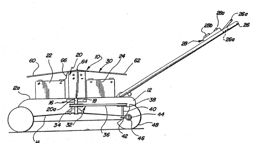
Reforring now to FIG. 1, a powered mower 10
i~ illu3trated including a protectivQ housing 12 for
a rotary blade 14. The blade 14 i~ susp-nded within
th~ prot~ctive housing 12 by a drivo train 16
including ~n electric clutch and brake unit 18. The
, drive train 16 i~ connect-d to a direct current
energized ~lectric drivQ motor 20 by the drive shaft
20a o~ the drive motor. The motor 20 is supported on
the top 12a o~ the protective housing 12.
~i ' '
: ',
', '
...
.
.
' , , :
. .
~ ~ ~ , ' . , , . -
W091/1~107 PCT~US91/02326
- 12 -
2~3~7
The powered mower lO is powered by a
primary source of power in the form of rechargeable
batteries 22, 24 located on either side of the drive
motor 20 where they are secured by suitable hold down
fixtures (not shown) to the top 12a o~ the protective
housing 12.
One feature of the present invention is
that the provision of an onboard source of power for
the drive motor 20 eliminates tho need for power
cords as presently ~ound on eloc~rically powered
mowers. The pre~ent invention thereby obviates the
attendant problem of accidental cutting of power
cords during mower operation.
Another featur~ of the pr~sent invention is
the provi~ion o~ a solar cell syste~ 30 ~or charging
the batterie~ during mower oporation to maintain the
rech~rgQable batterios 22, 24 at a ~unctional
operating 1eVQ1. The provision o~ an onboard
r-charging source eliminates th- neod to connect the
battori~s ~or recharging ~rom a cantral power source
30 as to eliminxte power plant emissions which can be
generatod during such reaharging. Initial charging
will be nocessary as may be periodic charging due to
some lo-s ~rom sitting, unless th~ mower is left in
.
`:
~' .
'` ~ -
.~,: : ., :
. :.- : - ., .: . . . .. - , - , , - . . .: ~' , . . . ' . ~ . ......... . .
: ~ ~ , - .
: :. ' . . . : - ,
. ' . - ' . ' "' -' ~ ' ~ " :
~ . .
-. . : . , , ~ . . -
WO91/15107 PCT/US91/02326
- 13 - 2~ 7
the sunlight after use until the next mowing. A
further advantage of electric powered mowers is that
they eliminate pollutants and emissions produced by
mowers of the type powered by either four or two
cycle engines fuel~d by existing sources of fossil
fuel. Such fossil fueled, internal combustion
engines do not include emission control systems and
in the aggregate produce co~bustion products that
constitute a substantial source of nitrous oxides,
carbon monoxide, carbon dioxide, as well as direct
evaporation of the fuel supply all requiring
regulation in order to protect the world environment.
A powered mower 10 having the aroresaid
rechargeabl~ batteries 22, 24 and solar cell
charging system 30 i~ readily adaptable ~or use with
known driv- systems. For exampls, the powered mower
10 can have a conventional handlQ 26 with a control
~odule 28 for sett~ng the control modes to cperate a
standard drive transmis~ion 32 having either a pulley
34 or a gear on th~ driv~ shaft 20a. A drive belt 36
from the pulley 34 pas~es over a driven pulley 38.
The driven pulley 38 can connect to a shart 40
carrying a worm gear 42 that engage~ a worm 44 on the
shart 46 of a drive wheel 48. ~uch a drive
transmission or its equivalent can be usQd to turn
i::
,,
: ':
,
;:
. - . ~ . ,
, ~ . . . . .:
- - , : ,
~ . :
,~, : ~ -:: , . . .
- .. .. . .. . .. .
WO91/15107 PCT/US91/02326
- 14 -
20~3~
the wheel (or wheels) of the powered mower lO
allowing the power from the onboard electrical power
source to pull the ~ower over grass terrain to allow
the rotating blade 14 to cut the individual blades of
S grass in a known manner.
In the illustrated arrangement and as best
shown in FIG. 2, the rechargeable batteries 22, 24
have negative terminals 50 thereof connected to the
negative terminal 52 of the D.C. drive motor 20 by
suitable leads 54. LiXewise the positive terminal 56
of the motor 20 is connected to either an on-off
switch 28a on the control module 28 or to a variable
speed control 28b thereon. When the switch 28a is
turned on the power circuit is completed across the
windings o~ the D.C. electric drive motor 20 through
suitable leads 58 conne~ted to the positiv~ t~rminals
59 o~ the ~atteries Z2, 24.
~f a varia~le ~peed control 28b i5 used,
th~ electronic speed control can produce a known
pulse width modulated signal to the winding~ of the
; drive motor 20 to vary the r.p.m. o~ the drive motor
20 to control the cutting speed o~ the blade 14
alone. I~ a transmission 32 is used to propel a
,~
~: `
.'~ .
,
~' . ' ~ , ' ' .
'
WQ91/15107 PCT/US91/02326
- 15 - 2~3~7
drive wheel 48, the speed of the entire unit can be
varied by varying the output speed of the drive motor
20.
The electric clutch 16 can serve as an
electric brake by directing opposite polarity power
thereto when a handle safety bar 26a is released. If
the user's hands are removed from the handle 26 the
safety release bar 26a conditions a safety switch 26b
to condition the clutch 16 to instantaneously provide
a 3top action for the cutt~ng ~lade 14. The clutch
16 also absorbs shock if the blade 14 strikes an
ob;ect.
lS As a ~urther safety feature, the onboard
powered electric motor 20 o~ the present invention
~an ba inætantly stopped by utilizing the safety
switch 26b to rev4rse the battery polarity to the
: ~lectric motor 20 when ~t i~ turn~ng the blad~ 14 in
it~ normal cutting diraction. Wh-n the motor stops
tha ~witch 26b disconnec~ th~ motor 20 ~rom the
batt~ries 22, 24 until the switch 26b is r~set to a
starting ~ode. Alternatively, an electromechanical
brako band can be provided to apply emergency braking
directly to a rotating clutch or dxu~ assembly
~ connected to the drive sha~t 20a.
:~;
:
.. ,~, . . .
W091/1~107 PCT/US91/02326
- 16 -
3~3~
In operation, the storage cells or
batteries 22, 24 are either dry charged or sealed
units which are installed on the mower as precharged
units from the manufacturer. If required the
batteries 22, 24 can receive their initial charge of
power from an external charging source. Once
charged, however, the batteries 22, 24 can be
operated for extended periods of time by utilizing
the solar cell system 30 as a supplemental power
source to maintain the initial charge on the primary
source of power de~ined by the batteries 22, 24.
,
The solar cell sy~tem 30, more
particularlyt include. a pair o~ solar panels 60, 62
joined at a ridge line 64 at a point raised above the
top o~ the electric dr~ve motor 20. Th0 solar panels
60, 62 each have a plurality o~ solar c-lls cbnnlected
so as to produce a voltage and current supply on a
lead lina 66 which ~ 8 genorated ag direct current and
voltagQ when the cells aro ~xposed to either the sun
or to a bright light source. A voltage regulator 70
; is connected either to a charging outlet 72 ~or the
initial charge or to the lead line 66 to control the
current ~low with respect to the batteries 22, 24.
The voltage regulator 70 is operative to maintain a
sa~e charging level of voltage and current as
~ ' ' ' '
;
,.. ..
.
.
W091tlS107 PCT/US91/02326
- 17 - 2~3~7
additional voltage and current is directed from the
solar cell system 30 to the batteries to maintain
them at a functional operating level.
In the embodiment o~ th* invention in FIG.
5, the solar panels 60, 62 are replaced by a
generally conically con~igured solar panel 80. In
both the case of the solar panel 60, 62 and the
conically configured solar panel 80, the solar cell
system 30 is operative to intercept sun rays from a
plurality of directions during operation of the mower
lO as the mower is passed in different cutting
patterns across a lawn surface.
In all of the a~orodo6cri~d ~m~odiments of
the invent~on, a well as th~ ~ollowing embodiments
o~ the i m ention, the use of solar c~ car~ied,
mounted or ~ttachsd to the cutting device operate so
as to supply a~charging voltage and current to the
battery to extand the cutting time o~ the cutting
d~vlc- and to ~upply a convenient method of charging
the ~attery a~ter and during its use, and to increase
the lire o~ the battery.
.
` .
';
::
.
;~: ` . . - .
: ::: : :
-
WO91/15107pcr/us91/o2326
- 18 -
2~3~
The extended cutting time and extended life
of the battery is accomplished due to the solar cells
supplying voltage and current to the battery while it
is in use, thereby rsducing the internal resistance
of the battery, allowing the battery to produce or
supply more current to operate the cutting motor for
a longer period of time.
By reduclng the internal resistance of the
battery while it is in use, the internal stress load
of the battery is reduced while it is supplying
volta~e and current to the motor load. Accordingly,
internal heat and plate warpage are reduced and the
battery has a longer life.
~ Since recharg~ time i~ in direct proportion
,~ 'to the time that the mower is u ed, the recharge time
can ba reduced due to the battery retaining more of
its energy, as long as the battery is not drained
completely.
Automobile type batteries, otherwise known
as starting batteries, are not useful devices for
cutting equip~ent. They can supply high current for
only a short period of time and cannot withstand deep
cycle discharge and recharge without damage.
,:
. ,~ .
- . ~ . - . . ~ - .
WO91~1~107 PCT/US91~02326
- 19 -
2~3!~7
Special design ndeep cycle~ batteries such
as, but not limited to, gell cells, nickel cadmium,
sealed recirculating gas and other irdeep cycle" non-
spillable types are designed for deep cycle discharge
and recharge on a continuous basis without damage.
Such batteries are able to supply the necessary
current over a longer period of time, allowing the
cutting device to perform useful work without damage
or dangerous spillage of their internal liquids, or
the release of dangero~s gasses.
The solar cells or photo voltaic cells used
on or attached to the cutting or mowing device are
not limited to solid, brittle types such as
crystalllne silicon type~. Flexible or conforming
typ-s caD be applled in any con~lguration, such as
a~orphous ~ilicon whlch can be sprayed on, dipped
onto or otherwi-Q applied to any given surface,
alloving utilization o~ the entire deck or chassis or
baqging unit as a solar gen~rator. ~he flexible type
can b- used in con~unction wlth the solid types of
solar cells to allow maximum power generation for the
mower or cutter application.
. ,~
.,
. ~ ~
'`~ Ii ~ :
~.j . . , '
WO91/15107 PCT/US91/02326
- 20 -
20~a~57
Furtherj the solar cells or solar panels
can be designed and constructed as a ~retrofit unit"
to be applied onto existing battery oper~ted or
battery powered mowers or cutting devices to perform
the sa~e function as herein described.
Referring now to the embodiment of the
invention shown in FIGS. 6 and 7, a solar powered
mower 82 is shown having a mower deck carrying an
electric drive motor 84 for the cutting blade which
is like the blade shown in the previous embodiments
which is connected to the output shaft of the
electric drive motor 84 by suitabl~ power train
components (not shown). In this embodi~ent the solar
panels 90 for defining a secondary source of
electrical power for charqing a battery 86 that
-- powers the electric drive motor 84 are mounted on~the
sides, top and front of a mower deck 88. More
particularly there are two ~ide solar panel~ 90a, 90b
which are connected one either side of the mower deck
88 and arrang~d at an angla which is best suited for
a particular latitude in which the mower is used. In
the illustrated arrangement the angle is
approxi~ately 45 degrees from the vertical which is
~est suited for more northern latitudes. The mower
;
; 82 further includes a front solar panel 90c arranged
':
. .
:. - .
. . .: ~ : : : . - - .; - . - :
. ..... : : . . . - -
~: : : . - . . : . . - . - . .
. . - -
WO9l~lSl07 PCT~US9l/02326
- 21 -
2~03~7
on the front of the mower deck 88 and arranged at a
similar angle. The mower 82 further includes a
horizontal solar panel sod covering the motor 84.
Additionally, a solar panel soe is supported on the
push handles 82a, 82b of the mower 82. In all cases,
the positive and negative terminals of each panel are
connected to the ter~inals of the voltage regulator
70 as shown at 67 in FIG. 2.
10The embodiment of the invention shown in
FIG. 8 includes a solar powered mower 92 having a
drivo motor 93, storage battery 95, and charging
circuit 97 like that in the embodimen~ of FIGS. 1-4
but in this embodiment the s~condary source of
electrical power for charging the power battery is
,~ defined by solar panels or c811s 94a, 94b and 94c
;~ . mounted on the outer surfac~ of a rear mounted ~rass
collector 96 connected to the deck 98 o~ the mower 92
at the aft end thereof.
The embodimont of tho invention shown in
FIG. 9 is a outrigger solar power mower 100 which
includes a deck 102 having a electric drive motor
~` 104. A primary power sourco for the electric drive
motor 104 includes a battery 105 connected to a
charging ~ircuit 106 for receiving power from a
':
. '
:.~ ` ` ,:
- . - ~ . . . - . .
. . : .. . .
WO91/15107 PCT/US91/02326
- 22 -
2~a3~7
secondary power source in the ~orm of a pair of
spaced solar panels 108, 110. Each of the solar
panels 108, 110 is carried on a outrigger panel 112
that is pivotable between a run position shown in
S FIG. 9 and a storage position shown in outline form
at 113 in FIG. 9. More particularly, the outrigger
panels 112 each have an inboard edge 112a connected
by hinges 114 to raised brackets 115 on the mower
deck 102. The outboard ed~e 112b of each of the
outrigger panels 112 have wheels 116. Lock members
118 on sach panel edge 112b snap together to hold the
outrigger panels toge~her in the raised position 113.
, .
When the solar powcred mower 100 is stored
the outrigger panels 112 are pivoted upwardly about
the hinges 114 until the lock member~ 118 are engaged
at which point the solar panels 108, 110 are located
within th~ outsid~ sid~ dimensions o~ the deck 102 so
as to derine a compact storage con~iguration.
The embodi~ent o~ the invention shown in
FIG. 10 i~ a rider mower 120 having a rear mounted
seat 122 and a ~ront located housing 124 which
encloses an electric drive motor, electric storage
battery and suitable charging and power circuitry for
interconnecting them to a solar power source 126 on
.~ . ~'.
'
'
.:
'
- . . . . . . . ..
- . . . :- .
.: . . . : : . : -
. . ~ - ., , , - ~ . . -
WO91/15107 PCT/US9l/~2326
- 23 - 2 ~ ~35 7
the rider mower 120. The charging and power circuits
are like those described in the embodiment of FIGS.
1-4. In this embodiment the solar power source 126
includes a frame 128 on the front housing 124 which
carries solar panels 130-134 for exposure to the
sunlight to produce a charging current flow to a
battery pacX ,'not shown) for an electric drive motor
for driving a cutting blade in a cutter deck 136 as
well as a transmission 138 for transferring power
rom the drive motor to rear drive wheels 140. The
; drive train can take many forms and this embodiment
is not cited for the drive train type but rather for
another arrangement for supporting solar panels for
charging an electric storage battery ~or powering the
electric drive motor of a rider mower.
.
The embodiments o~ the ~nvéntion shown in
FIGS. lOA and ti OB ~how arrangements ~or supporting
solar pan ls above a rider motor on sunroofs thereof.
The embodi~ent of FIG. lOA shows a roof type mount
wher-in sclar panels 142, 144 are formed on a sloping
roof 145 for protecting the dxiver of the rider
mower. The embodiment of FIG. lOB shows a solar
panel 146 formed on a flat roo~ 148 for protecting a
driver.
~ ,~
. ~ . - . . , ~ .
. . - : . , ~ ... -
WO9l~lS107 PCT/US9i/02326
~ 7 24 -
The em~odiment of FIG. 11 shows a rider
mower 150 having a center mounted seat 152 located
above a ride platform having a mower deck 154 and a
front mounted steering pedestal 156. A side outlet
S 156 from the mower dec~ 154 is connected by a
discharge chute 156 into a rear grass collector lS~.
In this embo~iment the source of secondary power for
charging an onboard electric storage battery for
powering an electric drive motor is comprised of
solar panels 160, 162, 164 carried respectively by
the pedestal 156, the seat frame and the top of the
rear grass collector 158.
; : ' ,'
FIG. 12 shows a solar garage or shed 160
for housing a solar powered mower of the type set
forth above. The solar garage has sides and a roof
162, 1l64 respectively for protecting the mower. It
also includes a solar panel 166 ~ormed either on a
slope or flat to collQct solar energy. The solar
panel 166 has ter~inals thereo~ connected to a power
cord or to a power plug 168 that will connect to
spad~ terninals 170 on the front of the power mower
when it is housed within the solar housing. In FIG.
12A th~ housing is shown in the ~lat roof 172 version
and in FIG. 12B a garage version 174 is shown
'' ~ . .
~ ~ .
,
~: : - - - -
WO91/1~107 PCT/US91/02326
- 25 -
2~80357
including panels 174a, 174b having a power cord 174c
adapted to connect to a charging receptacle 176 on a
riding mower 178.
~he above-described mower housings and
garages all carry solar panels which can be used to
charge storage batteries on solar powered mowers and
in conjunction with the solar panels carried on such
mowers or as a separate source of power for electric
storage batteries on mowers that have an electric
drive motor but do not have onboard solar panels. In
both cases, however, the shed, g~rage or other
shelter which carries the solar panels will serve to
protect the mower rrom the element~ when not in use
while charging the onboard electric storage batteries
of the mower when the sun is out.
In all cases, the maximu~ solar charging
efficiency is achieved by the proper orientation of
the solar panels to achieve maximum exposure to the
suns ray~. Thus in latitudes closer to the equator
the solar panels arQ arranged mor~ horizontal to
capture rays from a sun position more overhead which
more northern and sou~hern latitudes will require
.' ~
,
~: !
, . ~ .. ~ . : . ... ~. -
, . ~...... .. . . . . .. - - ,
.
WO91/15107 PfCT/US91/02326
20~a3~ - 26 - ~
solar panels inclined more toward the vertical to
capture rays from sun positions lower toward the
horizon.
As shown in FIG. 14, a safety switch 180 is .
utilized on the mower to preclude its starting or
running when the cutting device is tilted or tipped
in extreme directions. This switch is a mercury
switch 180 mounted on a pedestal 182 on mower decX
which is able to be oriented to actuate or deactivate
- the electrical continuity to the running circuit
through wire 58.
.~ ~ As show~ in FIG. 13, a capacitor 184 may be
lS placed across thef output o~ the solar panfefls 186 to
-...... . stabilize the output voltage delivered to the battery
18~. ,
':4~ ~ '
Thus, during sunlight period~ when the
panels 186 supply current, thef capacitor 184 stores
the output o~ the solar cells while, at the sa~e
ti~e, allowing the battery to be charged by the solar
cells. Then, when shade isf encountered and the solar
cells are not producing surficient current, the
stored enerqy within the capacitor 184 is discharged
: into the battery 188 until ths solar cells receive
:'; :
W091/15107 PCT/US91/02326
- 27 - 2 ~g ~3.
additional sunlight, thereby to continue charging the
battery and recharging the capacitor. The capacitor
must be at least the rated voltage output of the
solar cell or cells to withstand the voltage and can
be as high a capacity as necessary to be able to
deliver its charge for a given amount of time.
A diode l90 is placed in series with the
charging circuit 192 to prevent voltage and current
feedback from the battery 188, during period of no
sun, when the panels are not producing voltage. The
diode 188 thereby prevent the voltage and curr~nt
from the battery reaching the solar cells so as to
damage the~.
In all cases, the protective housing of the
mower can be upsized to accommodate a larger number, :
of rechargeable batteries to drive a larger load and
likewise a larger support base i9 proviiQd to
accommodate a larger area of solar cQlls to provide
the secondary source o~ power ~or charging the
batteries.
.' ' '.
~: :
,.
; '': ` -
WO91/15107 PCT/US91/02326
2~03~7 - 28 - -
While representative embodiments of the
present invention have been shown and discussed,
those skilled in the art will recognize that various
changes and modifications may ~e made within the
scope and equivalency range of the present invention.
,
.:
,, .
: ;~ , - . . ~. .....