Note: Descriptions are shown in the official language in which they were submitted.
CA 02080616 1999-11-16
- 1 -
ENDOSCOPIC MULTIPLE LIGATING CLIP APPLIER
WITH ROTATING SHAFT
FIELD OF THE: INVENTION
Generally, this invention relates to ligating clip
appliers. More specifically, this invention relates to
endoscopic ligating clip appliers. Most specifically,
this inveni:ion relates to endoscopic ligating clip
appliers, where the applier is capable of placing down a
sequential number of clips from a multiple clip applying
cartridge.
BACKGROUND OF THE INVENTION
There have been many advances in recent years in the
field of endoscopy. Many of these advances have come due
to the increased versatility of endoscopic staple and clip
applying mechanisms. These mechanisms are placed through
the cannula of an endoscopic trocar so that tissue may be
cut, stapled or ligated. With use of these endoscopic
stapling and l.igating mechanisms, there have become
available means for the proliferation of endoscopic
ligating procedures.
With the advent of these devices, however, there have
been certain noted inadequacies. Many of these
inadequacies have become perceived solely because of the
newness of the endoscopic procedures. Thus, there has
been a great opportunity for the discovery of new needs
SEN-91
~o~o~~~
- 2 -
and desires of each individual surgeon, and therefore an
explosion in the necessity to meet these requirements.
For instance, there has been perceived a need for
venting such an endoscopic applier, in order to equalize
pressures within the instrument and to provide a path of
least resistance for fluid flow within the instrument.
The equalization of pressures minimizes the possibility of
failure of the instruments.
In addition, there has been a perceived need for
adequate clip advancing mechanisms in order to both
longitudinally (along the long axis of the instrument) and
transversely support both the clip closing mechanism and
the clip during such surgeries.
Also, there has been perceived a need for a mechanism
to vary the gap of a ligating clip when closed within the
mechanism.
There is yet another perceived need for a mechanism
which guarantees that the jaws of the instrument are open
when a clip is fed into these jaws. This mechanism
insures clip presence during ligating procedures.
There is yet another perceived need for a mechanism to
lockout the firing mechanism instrument after the last
ligating clip in the cartridge of clips has been fired.
Yet another perceived need is for a restricting means
to minimize proximal movement of the clip during
application into a vessel. This limitation of movement
maintains the ligating clip within the proper forming area
of the jaws during ligation.
SEN-91
~J~0~1~
- 3 -
One additional need is to create a resistance to the
torque acting on the endoscopic applier shaft. Resistance
of such torque minimizes any transverse deflection of the
endoscopic applier tip during usage. Such torque
resistance promotes clip placement accuracy.
Still another perceived need is to create smaller jaw
spacing, which allows the usage in a smaller cannula
during endoscopic procedures. One additional problem
20 encountered in the resolution of this problem is that one
must minimize the spacing of the jaws, while still
compensating for the torques created during jaw closure.
Yet another perceived need is for a system which
minimizes the possibility of double feeding of clips into
a clip applier jaws. Such a system may be perceived as
the use of a series of valves and springs in order to
properly place only one clip within the jaws of the
instrument at any one time.
One additional need is for a mechanism which seals an
endoscopic clip applier, to prevent the gross loss of
pneumoperitoneum, during operations. Such sealing is
necessary to maintain pneumoperitoneum throughout the
procedure.
one further perceived need is for a method wherein the
synchronized feeding of clips into the jaws of an applier
is coordinated with the opening and closing of these jaws
during use.
SEN-91
2~~0~16
- 4 -
Another final perceived need is for a mechanism which
prevents backup of a clip about to be fired within such an
endoscopic clip applier.
Therefore, it is to be realized that while there
currently exist certain endoscopic clip appliers, it
continues to be still important to improve on these
appliers in many various areas where there are perceived
deficiencies or inadequacies.
SUh~HARY OF THE INVEN TON
Accordingly, it is an object of the invention to
provide an endoscopic multiple ligating clip applier With
an adequate venting system to maintain the instrument from
functional failure.
It is yet another object of the invention to provide
a multiple ligating clip mechanism which provides for clip
closure without the threat of dropping the clip from the
instrument into the wound site.
It is yet another object of the invention to provide
a clip closure cam channel for a multiple ligating clip
instrument, so that closure of the ligating clip is
improved.
It is yet another object of the invention to provide
for a feature which retains the jaws in a "positive open"
position, so that a clip will be fed into a pair of open
jaws. This improves the reliability and performance of
the mechanism.
SEN-91
20~0~~~
_ g _
Lt is yet another object of the invention to provide
i:or a lockout mechanism which causes the instrument to be
locked out once the last clip from the magazine is fired.
It is yet another object of the invention to maintain
the clips on the jaw site during closure. With security
in the motion of the clips within the jaws of the
instrument, this enables the user to be assured of more
precise spacing of clip legs and, resulting in an improved
to closure within the instrument.
It is yet another object of the invention to provide
for a torque resisting shaft for a multiple clip applier
which minimizes transverse deflection of the tip of the
instrument. Such minimunization promotes improved clip
placement and accuracy during firing.
It is yet another object of the invention to provide
within a multiple clip firing instrument, an anti-torque
feature on the jaws of this device. This feature should
be designed to allow the size of the jaws to be minimized,
while still maintaining and providing adequate clip
closure characteristics.
An additional object of the invention is to provide
for an endoscopic ligating clip applier which permits the
user to place a clip automatically, through' a trocar
cannula, without having to load a clip after placement of
the mechanism in the endoscopic cannula. This will depend
on the user's ability to keep the jaws spaced apart upon
insertion into the cannula with a clip therein.
Yet another object of the invention is to provide for
a clip feeding system which improves the clip feeding
SEN-91
20~0~~6
- 6 -
reliability by minimizing the possibility of double
feeding of the clips into the jaws.
It is yet another object of the invention to provide
for a sealing system within the endoscopic multiple clip
applier so that it maintains pneumoperitoneum throughout
use of the system.
one other object of the invention is to provide a
timing mechanism for an endoscopic multiple clip applier
wherein it is assured that a clip is fed into the jaws of
the mechanism at the precise moment between when jaws are
fully opened to accept such a clip and before the
instrument is released to its open position.
It is yet another object of the invention to provide
for a tissue stop which prevents tissues or vessels held
within the clip applier from being improperly positioned
on the instrument. Such a mechanism is advantageous in
order to promote secure clip closure and placement within
the context of a multiple fire ligating clip mechanism.
These and other objects of the invention are provided
for in an endoscopic ligating clip device which contains
a firing mechanism held remotely from an endoscopic clip
applying portion by a long solid cannula. The device is
created so that the clips are applied in one orientation,
but it is understood that the clip applier can be rotated
to advantageously orient the system. Within the clip
applying mechanism there is described a venting system
which comprises a channel through which the device may be
vented. This helps insure adequate firing within the
system. There is also described a feed bar support
mechanism which contains a pair of protrusions which
SEN-91
~o~os~~
prevent the deflection of the clip applier jaws during its
insertion into the cannula. Furthermore, there is
described a cam channel mechanism which provides a uniform
closing force upon the ligating clip held within the jaws.
A tab within the cam channel prevents the jaws from
closing, so that these jaws may assurably receive a new
clip after the instrument has been fired to place a clip
around tissue.
Other novel features are provided in this system.
First, there is a mechanism comprising a lever Which falls
into the firing path of the device so that the instrument
cannot be fired after the last clip has been fired from
the mechanism. Second, a finger located on the clip
applying mechanism is described, which secured holds the
clip about to be fired in place on the jaws of the
instrument. Third a torque-resisting shaft is placed on
the instrument, to prevent transverse deflection of the
tip of the instrument during firing.
Another set of unique features of the instrument are
such things as a pair of jaws provide for multiple contact
during firing, to minimize deflection in the arms of the
jaws, enabling proper closure of the clip. This
minimization of deflection provides for more consistent
and improved clip closure. A clip feeding escapement
system provides that only one clip is actually applied to
the open jaws after the clip has been fired. Furthermore,
there is a sealing system provided for in the mechanism
which adequately provides the sealing of pneumoperitoneum.
Also, there is located on the shroud of the instrument a
v°shaped notch, which helps maintain the tissue on the
jaws of the instrument. This notch helps secure proper
SEN-91
_g_
position of the tissue for firing of the instrument
and clip closure.
Furthermore, the clip applier presents a
streamlined profile, enabling one to emplace a clip
between the jaws of the applier, and then place the
applier in a trocar cannula. Because the clip
reliably stays in place, this allows the user to avoid
loading of clip within the trocar cannula. Also,
because the clip applying mechanism is presented in an
alternate rotatable embodiment, this allows the user
to orient the clip applier at any desirable position.
According to a broad aspect of the present
invention there is provided an applier mechanism for
individually applying a plurality of surgical closure
devices. The mechanism comprises a shaft portion, a
handle portion, and a rotating means extending
distally of the handle portion for connecting the
shaft portion to the handle portion so as to permit
rotation of the shaft portion about an axis extending
through the shaft portion. Applying means is
positioned in the shaft portion for applying a
surgical closure device. Feed means is positioned in
the shaft portion for delivering a closure device to
the applying means. Actuation means is positioned in
the handle portion for actuating the applying means
and the feed means. A first connection attaches the
applying means to the actuation means to permit
rotation of the applying means with respect to the
actuation means upon rotation of the shaft portion by
the rotating means. A second connection attaches the
feed means to the actuation means to permit rotation
of the feed means with respect to the actuation means
upon rotation of the shaft portion by the rotating
means. The first and second connections are
~o~oo~~
positioned in the rotating means and rotate about a
common axis extending through the shaft portion and
the first and second connections are spring biased
from one another within the shaft portion.
This device has been described in connection with
a number of various features contained in its
embodiment. These features will be better understood
when taken in connection with the attached Detailed
Description of the Drawings and described in
connection with the following Detailed Description of
the Invention.
DETAILED DESCRIPTION OF THE DRAWINGS
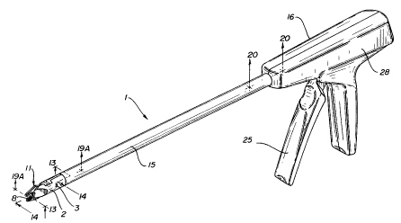
Figure 1 is a perspective view of the left hand
side of the endoscopic multiple clip applying
instrument of this invention;
Figure 2 is a side plan view of the instrument of
the invention in the open position;
Figure 3 is a side plan view of the instrument of
the invention in the closed position;
Figure 4 is a perspective view of the instrument
of the invention inserted through a trocar.
20~0~~0
_ g
Figure 5 is an assembly view of the handle of the
invention;
Figure 6 is a partial cut-away view of the handle of
the invention in its relaxed position.
Figure 7 is a partial cut-away view of the handle of
the invention in its firing position;
Figure 8 is an assembly view of the tubular endoscopic
portion of the instrument of the invention;
Figures 9, 10 and 11 are sequential plan views of the
clip as placed in the jaws of the invention when in the
open, closing and closed positions respectively:
2 t3
Figure 12 is a longitudinal cross-sectional view of
the invention taken across lines 12-12 as seen in Figure
2t
Figure 13 is a cross-sectional view of the invention
taken along lines 13-13 as seen in Figure 1;
Figure 14 is a cross-sectional view as taken across
lines 14-14 of Figure 1:
Figure 15 is a cross-sectional view of the invention
describing the cam channel mechanism taken across lines
15-15 of Figure 2;
Figure 15A is a cross-section view taken across lines
15A-15A of Figure 15:
SEN-91
- 10 -
Figure 16 is a cross-sectional view of the invention
describing the handle-latch combination:
Figure 16A is a cross-sectional view of the invention
taken across lines 16-16 of Figure 3 emphasizing the
lockout mechanism used in the endoscopic clip applier~
Figure 16B is a cross-sectional view of the invention
taken across lines 16-16 of Figure 3, emphasizing the
rearward retention mechanism for the clip applier in the
open-state with an unformed clip of the inventions
Figure 16C is an identical view as Figure 16B, except
that it demonstrates the jaws in a closed state, with a
formed clip;
Figure 17 is a plan view of the jaw component of the
invention;
Figure 18 is a view of the jaw as seen in Figure 17
when in the closed position:
Figure 18A is a cross-sectional view across lines
18A-18A of Figure 18;
Figure 18B is a cross-sectional view across lines
1sB-18B of Figure 18:
Figure 19A is a cross-sectional view of the clip
feeding escapement system of this invention across lines
19A-19A of Figure 1;
Figure 198 is the view of Figure 19A in the closed
position;
SEN-91
- 11 -
Figure 20 is a partial cross-sectional view of the
shaft assembly across lines 20-20 as seen in Figure 1;
Figure 21 is a cross-sectional view of Figure 20 as
seen across lines 21-21 of Figure 20:
Figures 22A, 22B and 22C are sequential views of the
clip feed timing mechanism of the invention;
Figure 23 is a perspective view of the clip applying
mechanism of the present invention;
Figure 24A is schematic of the rotational portion of
the mechanism of Figure 23 in a non-firing position;
Figure 24B is a schematic of the mechanism in Figure
23 showing the rotating portion in a firing position.
Figure 25 is a top plan view of the rotating portion
of the mechanism of Figure 23;
Figure 25A is a cross-sectional view of the angular
positioning of the detents of the rotating mechanism as
seen in Figure 25: and
Figure 26 is a cross-sectional view of the rotating
mechanism of Figure 25 as seen across lines 26-26 of
Figure 25a.
DETAILED n~'SCRTPTTON OF THE TNVENTION
This invention is better disclosed by an endoscopic
multiple ligating clip application mechanism 1 one as seen
SEN-91
2~~a5~~
- 12 -
in Figures 1-22. As better seen in Figures 1, 2, 3 and 4,
this multiple ligating clip mechanism 1 is useful for
applying clips through a surgical trocar. As seen in
Figure 4, the ligating clip mechanism 1 is applied through
the cannula 105 of a trocar 100, so that a vessel can be
occluded or tissue can be clamped. The mechanism applies
a series of clips 8 by means of jaws il which are fired
remotely by a trigger 25. As seen in Figures 2 and 3, the
trigger 25 is compressed, causing the jaws 11 to close,
and squeezing a ligating clip 8 therein. After closing
the clip 8, the jaws 11 are released and there is loaded
another clip 8 in its place.
As better seen in Figures 4 and 9, it is an intention
of this clip applier mechanism 1 to present a pair of jaws
11 which are maintained in a smooth and streamlined
profile around ligating clip 8. Specifically, an
intention of this invention is to allow the jaws 11 to fit
around ligating clip 8 so that they are relatively the
same dimensional width as the diameter of the barrel which
forms support tube 15 of the ligating clip mechanism 1.
In this way, the clips 8 can be emplaced between jaws 11
outside of the cannula 105 of trocar 100. As will be
later explained, because the jaws 11 reliably maintain the
clip 8 firmly held in place between each of the jaws 11,
the user can reliably place the clip 8 between the jaws
il, and then insert the entire instrument including tube
15 into cannula 105.
In contrast to other systems, there is no need to load
a clip 8 after insertion of the jaws il within the cannula
105. The positioning of jaws 11 allows its insertion in
an open condition with clip 8 maintained therein into
cannula 105 of trocar 100. This is in direct contrast to
SEN-91
20~0~~.6
- 13 -
former systems wherein similarly configured jaws must be
brought together to roughly the size of this mechanism's
open jaws il, in order to fit within the cannula 105 of a
typical surgical trocar 100. This advancement allows this
particular clip firing mechanism 1 to be fully automatic
rather than a mechanism which must be loaded separate from
the firing sequence.
As batter seen in Figures 5, 6 and 7, there is
described handle halves 16, 28 which enclose the trigger
25 mechanism for firing the device. The handle halves 16,
28, surround the firing mechanism and afford a pivot point
110 around which trigger 25 rotates. Trigger 25 is
associated with a former plate 22 and a feeder link 23.
As seen on the right hand side of Figure 5, feeder link 23
is attached to the trigger 25 and holds in place the
feeder plate 24. Feeder plate 24 is connected to return
spring 27, at post 24a which is in turn connected to a
post 22a on former plate 22. Thus, when the trigger is
~20 fired, the former plate 22 is pushed forward. Pivot 113
on trigger 25 slides in channel 115 in handle half 16 and
causes slot 111 to be urged toward the rear of the
instrument. Slot 118 on feeder link 23, in turn, causes
feeder plate 24 to be urged to the rear of the instrument.
Simultaneously trigger 25 rotates so that slots 114 causes
dowel pin 26 to slide in slot 112 of plate 24. Also,
dowel pin 26 urges point 116 in former plate 22 forward,
as it slides within slot 117 in handle half 16. When the
trigger 25 is released, the tension on return spring 27
causes the trigger 25 to return to its position, by acting
upon feeder plate 24 through post 24a and former plate 22
through post 22a so that trigger 25, dowel pin 26, and the
former plate 22 are moved back to their non-stressed
position. Dowel pin 26 holds feeder plate 24 in place on
SEN-91
20~06~.6
- 14 -
right handle 16. An anti back-up lever 19, lost motion
lever 18, latch 17, and torsion spring 20 and pre-cock
trigger 21 will all be further described as part of this
invention.
When the trigger 25 is activated, the former plate 22
is caused to move forward so that cam channel 12 connected
to former plate 22 within support tube 15 is moved
forward. This actuates the endoscopic clip applying
mechanism. As seen in Figure 8, the feed bar 9 and cam
channel 12 surround floor 10. These mechanisms are sealed
between lower shroud 13 and seal cap 14 within the support
tube 15. Attached to cam channel 12 is jaw 11. This jaw
will close about a ligating clip 8 to seal tissue or
vessels.
Held in clip track 4 is feeder spring 5, lock lever 6,
feed shoe 7, and a series of clips 8. The clip track 4 is
capable of advancing forward a series of clips and
loading them Within the arms of jaw 11. A lifter spring
3 is held in place over clip track 4 by top shroud 2, and
will place the first clip 8A of a stack of clips 8 into
the plane of feed bar 9 to be positioned into jaws 11.
Also, the seal cap 14 and lower shroud 13 hold cam channel
12, floor 20 and feed bar 9 in place within the support
tube 15.
In operation, the trigger 25 is fired and former plate
22 causes cam channel 12 to move forward. Cam channel 12
encloses jaws 11 to seal a clip 8 around tissue. After
trigger 25 is released, cam channel 12 retracts so that
jaws 11 open. The magazine of clips 8 is advanced forward
so that another clip 8 is held within jaw 11. This occurs
when spring 27 is released, causing feeder plate 24 to
SEN-91
~~so~l~
- 15 -
advance. This in turn causes feed bar 9 to advance the
first clip 8a from the stack of clips 8 which has been
positioned in the path of the feed bar 9 by spring 3 into
jaws 11. This operation can best be seen by observing
Figures 9, 10 and 11 in conjunction with Figures 6 and 7.
Of course, each of the mechanisms as disclosed by this
invention will be further described herein.
Specifically, it is to be noted that the orientation
of clips 8 is transverse to that of the orientation of the
handle portion of the instrument 1. In this way, the user
is able to grip the trigger 25 on the handles 16, 28 of
the instrument 1 so that the user's hand is held parallel
to the plane on which the clips are fired. This affords
a more typical reference point for the user, so that it is
more comfortable for operation of the instrument.
Now, each of the various features of the clip applying
mechanism will be described. The first feature is a
venting system for endoscopically applying these clips.
As seen in Figure 12, there is located a vent 120 on the
outside of the instrument. This vent 120 is attached to
an open channel 122 within the lower shroud 13 within the
support tube 15.
Open channel 122 is connected to a hole 124 in the
lower shroud 13. This allows fluid passage between tube
15 and lower shroud 13. This hole in lower shroud 13
affords fluid passage between the upper portion 126 of the
instrument and the inner channel within lower shroud 13.
This open channel 122 within support tube 15 runs along
the longitudinal axis of the support tube 15 and provides
a path of least resistance for fluid flow. The hole 124
in the lower shroud 13 at the end of this channel 122
SEN-91
20g~~1~
- 16 -
provides a venting path to the upper portion 126 of the
shaft assembly. Fluid is therefore vented from the
instrument 1. The instrument is much more capable of
functioning under between 10 and 15 mm mercury pressure.
Pressure is equalized across the entire instrument, and a
path of least resistance is provided. In this way, the
likelihood of functional failures of the instrument when
used interoperatively is reduced.
Furthermore , as seen in Figures 13 and 14 , there is
also disclosed a support mechanism for the endoscopic
multiple clip applier. This support mechanism provides
longitudinal support for the ligating clip 8 during
application onto tissue, and transverse support of the
jaws il during insertion through the cannula 105 of the
trocar during endoscopic surgery. As seen in Figures 13
and 14, when the instrument jaws il are opened the
ligating clip 8 is positioned between the jaws 11A, 11B of
the instrument. The feed bar 9 is advanced completely
forward. when the instrument is inserted through a
cannula of a trocar and applied to tissue it is important
that the jaws are prevented from closing. As seen in
Figure 14, there are outboard protrusions 132 on the feed
bar 9. These outward protrusions 132 contact the angled
arms 134 of the clip 8 in the jaws. Also, the feed bar 9
has a tapered outer edges 130 which contacts the inner
edges 136 of the jaw 11.
Thus, jaws 11A, i1B are prevented from being squeezed
transversely during insertion through a cannula 105. The
outboard protrusions 132 prevent the clip 8 from moving
longitudinally during insertion, and the outer edges 130
of the feed bar 9 prevent the inadvertent jaw closure
during insertion. This aspect advantageously promotes
SEN-91
2~8~~~~
-
improved clip closure and prevents dropping of a clip from
the instrument into the wound site during usage.
Another feature is the clip closure cam channel 12
used in this instrument. Cam channel 12 helps close the
jaws 11 of the ligating clip instrument. The cam channel
mechanism 12 travels longitudinally along the axis of the
tubular support tube 15 of the instrument. The cam
channel 12 lies in the longitudinal axis of the jaws 11.
The distal end 140 of the cam mechanism is rectangular and
cross sectioned; as can be seen in Figure 15. As in
Figure 15A, on the anterior surface of the cam channel 12
there is a dovetail joint 14_2, 142A, which holds the cam
channel 12 together mechanically. This dovetail
mechanical lock reduces the transverse (side-to-side)
deflection of the cam channel 12 during clip formation.
In this way, while the longitudinal motion of the cam
channel 12 takes place, transverse motion of the cam
channel 12 is prevented. Therefore, the dovetail
mechanical lock 142, 142A incorporated into the cam
channel 12 improves the dimensional stability cam channel
12 and improves the reliability of closure of the ligating
clip 8.
As also seen in Figure 15, there is described a pair
of tabs 144 in the cam channel- 12. These tabs 144 are
bent at the distal end of the cam channel 12 and are
oriented perpendicularly through the longitudinal axis of
the jaw 11 of the instrument 1. When jaws 11A, ilb'are
open, the outer edges of the tabs 144 rest on the arms of
lla, llb of the jaws 11, preventing them from being moved
inwardly toward each other, as during closure of the
mechanism. When there is a ligating clip 8 closed within
the jaws 11, the cam channel 12 retracts from the forming
:N-91
20~~~~.6
- 18 -
site and the edges of the tabs 144 again contact the edges
of the jaws il, forcing the jaws 11 outward. This
guarantees that the jaws are open to receive a clip. Clip
feeding reliability of the instrument is increased, while
not compromising the process of clip closure.
As seen in Figure 16A, there is also described in this
instrument a pivoting lock-out lever 6, which is attached
to the feeder shoe 7. The lever 6 pivots upon contact
with top shroud 2 into the path of the feed bar 9, as seen
in Figure 16A. This lever 6 when downwardly pivoted, as
seen in Figure 16a, prohibits the complete forward motion
of the feed bar 9. This then causes the biased latch 17
to engage wall 150 of the former plate 22, seen in Figure
16. Therefore, this multiple redundant system allows for
locking of the instrument after the last clip 8 is fired
at the forward end of the instrument by the jaws 11, as
well as at the rearward end of the instrument. The
lock-out lever 6 pivots into place only when there are no
remaining clips 8 in clip track 4. Had there been a
remaining clip 8, the feeder spring 5 would not have been
able to bias feed shoe 7 to clear the path for the
lock-out lever 6, such that lever 6 is caused to pivot
into the path of the feed bar 9. When this locking out by
lever 6 occurs, the feed bar is prevented from completely
moving forward and therefore the biased latch 17 engages
the.wall 150 of the former plate 22.
Also, as seen in Figure 16B, there is described a
mechanism that minimizes the rearward movement of a clip
8 in the applier during application onto the vessel. It
is also capable of maintaining the clip 8 in its proper
forming area throughout complete closure of the mechanism.
This mechanism comprises of the floor 10 held within
SEN-91
2~~a~~6
- 19 -
support tube 15. The floor 10 protrudes into the
longitudinal plane of the clip forming area 160 of the
jaws 11A, 11B of the instrument. A clip retaining finger
156 on the floor 10 is provided with a perpendicularly
bent tab 154 at its distal end, as seen in Figure 16B.
This retaining finger is unitary to the floor 10 and is
also biased so that it is parallel with the longitudinal
plane of the jaw clip forming area 160. Distal tab 154 of
the finger 156 is positioned perpendicularly to the
forming area such that the tab minimizes the rearward
movement of the clip 8 within the jaws 11A, liB. As the
jaws close, the floor 10 is ramped out of the plane of the
clip forming area. Yet, throughout closure of the clip
and ramping of the floor 10, the bent tab 156 of the clip
retaining finger remains in the plane of the clip 8 and
clip forming area 160 of the jaws 11A, 11B and is
positioned behind the apex of the clip 8. This is better
seen in Figure 16C. Therefore, the movement of the clip
8 as held within the jaws 11 is always controlled and the
finger 156 and tab 154 of the floor 10 constantly remain
in the plane of the forming of a clip 8.
As may be seen in Figure 8, support tube 15 is torque
resistant. That is, the support tube 15 is cylindrical
and hollow and is made of a non-resilient material. The
tube ends near the distal end of the shaft, and close to
the clip forming jaws il. It is connected to the top
shroud 2 so that the positioning of these elements
together provide the necessary resistive support of the
mechanism for the forming of clip 8. Because the material
from which the support tube 15 is made is nonresilient,
the stability of the instrument is increased and this
helps increase the placement accuracy of a clip 8.
SEN-91
2~~0~1~
- 20 -
As seen in Figures 17, 18, 18A and 18B, the jaws ilA,
i1B of the instrument are described so that they contact
at their distal end 178 and at primary heel 176 located
proximally to the closing ramps 172 of each jaw. This is
better seen in Figures 18 and 18A. As seen in Figure 17,
the jaws lia, iib are generally maintained in an open
position. The contact of the primary heels 176 minimizes
the deflection in the arms 172 of the jaws 11a, 11b to
properly close a clip 8. This initial contact minimizes
arm deflection and torque and supports the system during
loading.
When the jaw is fully closed, as seen in Figures 18
and 18B, the last portion of clip closure causes the
magnitude of loading conditions to increase. Two opposing
posts 174, called anti-torque posts, contact with each
other near the forming areas of the jaws and counteract
the torque placed on the jaws. This provides for a more
consistent and improved clip closure. Also, the tips 178
of each jaw contact. Thus, with the anti-torque mechanism
described herein, the jaws may be smaller in size as they
do not need to be as torque resistant. The jaws lla, llb
also provide improved clip closure mechanism because
deflection is minimized. This provides for reliability of
the instrument along with minimization of size.
As seen in Figures 19A and 19B, there is described a
feeding and escapement system which improves the clip
feeding reliability of the endoscopic multiple clip
applier 1. This is done by minimizing the possibility of
double feeding of clips into the jaws. The system
consists of two independent parts. A valve 182 unitary to
the clip track 4 holds the stack of clips 8 stationary
while the forward most clip is biased by lifter spring 3
SEN-91
20~~~1~
- 21 -
into the plane of feed bar 9. As the instrument is
actuated, the feed bar 9 is caused to retract toward the
rear of the instrument, and from the lifter spring 3.
When the feed bar 9 retracts, the ramp 180 on feed bar 9
is engaged with primary valve 182 located in the clip
track 4, thus, clip track 4 is closed.
When clip track 4 is closed, the stack of clips 8 is
held stationary. As the feed bar 9 retracts further from
lifter spring 3, valve 182 is closed by ramp 180, and
lifter spring 3 is actuated, causing the forward most clip
8 to be biased into~the plane of the feed bar 9 so that it
may be the next clip 8 loaded within the jaw. This is
better seen in Figure 19B. Only one clip 8, however, can
be biased toward the feed bar, because the primary valve
182 located in clip track 4 previously uses check port 184
to hold back any additional clips 8 in the clip stack.
The possibility of double feeding of clips is reduced,
improving the reliability of the applier.
As seen in Figures 20 and 21, there is disclosed a
sealing mechanism located near the proximal end of the
shaft assembly of the endoscopic multiple clip applier.
The sealing mechanism is circular in cross section and
fits tightly through four crushed ribs 196 within the
shaft support tube 15. Within the sealing mechanism are
three chambers 190, 192 as identified in Figure 20,
through which the feeding and forming mechanisms of the
instrument pass. The primary chamber 190 is an area
through which a sealant fluid may be injected. Sealent
may be inserted through insertion holes 194, 198. The
outer or secondary chambers 192 are provided as spill-over
areas for the sealant. This is better seen in Figure 20.
The ends of the sealing mechanism are closed to prohibit
SEN-91
2o~oo~s
- 22 -
the migration of sealant from the chambers 190 to the
functional areas of the instrument.
The sealing system provides a cushioning mechanism to
minimize instrument recoil during firing and retraction of
trigger 25. This closed sealing mechanism also prevents
the intraoperative gross loss of pressure through the
instrument itself, while minimizing, through ribs 196, the
possibility of instrument functional failure due to
to sealant migration. The system is sealed from outside the
patient, and it is itself sealed from the moving parts of
the instruments.
As seen in Figures 22A, 22B and 22C, the triggering
system taken in conjunction with Figure 5 consists of a
precook trigger 21, which is pre-stressed and pivots on a
post 206 into handle portion 16. Precook trigger 21 is
biased so that there is eliminated any clearance between
the precook trigger 21 and the former plate 22 located
within the handle portions 16, 28. As the feeder plate 24
is retracted to the rear of the instrument away from the
forming site (Figure 22B), during handle actuation, a
caroming surface 196 on the feeder plate 24 contacts a
cylindrical post 198 on the precook trigger 21. This
causes the rotation of the precook trigger 21 into its
precooked position as seen in Figure 22B.
In its precooked position a projection 200 of the
precook trigger 21 becomes locked behind a wall 202
extending from the former plate 22. The precook trigger
21 now blocks the path of a tab 204 extending from feeder
plate 24. The feeder plate 24 cannot feed the next clip
8 into the jaws from this point until the timing wall 202
extending from the former plate 22 allows the precook
SEN-91
2~~~~~~
- 23 -
trigger 21 to rotate out of the path of the feeder plate
24. This method of timing causes a sequencing operation
for feeding clips which eliminates the possibility of
feeding a second clip into the jaws 11 of the instrument
in the event that the instrument is partially fired and
re-opened.
As can be further seen in Figures 5 and 22C, torsion
spring 20 connects to both lost motion lever mechanism 18
and anti back-up lever 19. The objective of the anti
back-up lever 19 is to assure that a pressure is
constantly maintained on the jaws 11 by cam channel 12 as
the clip is being closed. Anti back-up lever 19 therefore
causes cam channel 12 to be constantly urged forward.
This prevents the clip 8 from falling out from the jaws
lla, llb until the applier is fully.actuated.
The system is actuated by rotation of the precook
trigger 21, so that the tab 208 extending from the base of
the precook trigger 21 into hole 210 of the lost motion
lever 18 (and thus connected to the anti back-up lever 19
via torsion spring 20) acts as a toggle mechanism to
engage and disengage the anti back-up lever 19. The hole
width 210 of the lost motion lever 18 determines the
relative motion of the precook trigger 21 and the lost
motion lever 18. This allows timing of the anti back-up
actuation mechanism 19 to be adjusted in relation to the
actuation of the precook trigger 21. The anti back-up
lever 19 is constructed of a resilient material and has
teeth 214 which engage the metallic teeth 212 on former
plate 22, as seen in Figure 5. The anti back-up lever 19
has a cam surface which tends to cam the teeth 214 away
from former plate 22, in the event that the anti back-up
mechanism must be overridden.
SEN-91
2~~~~~~
- 24 -
As seen Figures 9, 10 and 11, there is a tissue stop
located as a V notch 220 in top shroud 2. This tissue
stop is located on the rear end of the clip forming area
within the jaws 11. As seen in Figure 9, this maintains
the clip 8 within the forming areas of the jaws 11 and
guarantees proper gap size of the clips. It also prevents
the possibility of tissue damage by closing the clips too
loosely or too tightly. This idea promotes more secure
clip closure and minimizes the possibility of damage to
l0 tissue.
As seen in Figures 23, 24A and 24B, there is disclosed
a ligating mechanism 200 with a rotational collar 300
attached to shaft 215 and handle mechanism 216. All of
the mechanisms in the clip applying mechanism 200 are the
same as those in clip applying mechanism 1, except for
modifications made to the connections between the portions
of the clip applier which are maintained within shaft 215,
and the connections to those portions which are maintained
in the handle mechanism 216. These will be further
described below.
As seen in Figures 24A and 24B, there are described
former plate 222 and feeding plate 224 which are identical
to former plate 22 and feeder plate 24 of ligating clip
applier 1 except for their connections to feedbar 209 and
cam channel 212. This cam channel 212 and feedbar 209 are
also identical to cam channel 12 and feedbar 9 except for
their connections with the aforementioned former plate 222
and feeding plate 224. Therein, it is seen that ears
224x, 224b are maintained such that notches 224c on each
of the ears 224a and 224b are maintained around collar
209a. This collar 209a is rotational within the
connections 224c on feeding plate 224. This rotational
SEN-91
20~~~~~
- 25 -
connection allows the feed bar 209 to rotate in any
position with respect to the orientation of the feeding
plate 224.
Similarly, ears 222a, 22b correspond to notches 222c
on former plate 222. These notches 222c fit within a
collar 212a on cam channel 212. This allows the circular
collar 212a to rotate with any angular orientation about
the former plate 222. Thus, cam channel 212 can be
positioned along with feeding bar 209 in shaft 215,
regardless of the orientation of handle portion 216.
These connections contained in rotational portion 300
allow for the orientation of the ligating clip mechanism
in any regard with respect to the handle portion 216.
As seen in Figures 24A and 24B, the capability of
orientation while a distinctive feature must also allow
for firing and loading of the ligating clips. This is
accomplished in the unique loading and firing mechanism
maintained within the coupling of the former and feeding
mechanisms.
As seen in Figure 24A, a spring 302 is in a lenghtened
position. This is the generally "open" state of the
ligating mechanism 200, and the coupling 225 which
connects feeding plate 224 to feedbar 209 is pushed fully
forward. Thus, a ligating clip 8 has been placed between
the jaws 11 of the clip applier 200. (This occurs in the
same fashion as in clip applier 1.) Now, upon actuation
of the mechanism, the feeding plate 224 has been moved
rearward in the instrument, much as feeder plate 24 in
instrument 1. This causes the feed bar 209 to retract
within the shaft section 215 of the instrument ( further
causing coupling 225 to retract into handle 216.)
SEN-91
20~0~~6
- 26 -
Simultaneously, former plate 222 is moved forward
toward the clipping end of the mechanism. This causes
movement of the cam channel 212, to cause the jaws 11 to
clinch clips 8. However, because there is relative motion
between the outer and inner mechanisms which connect the
forming and feeding systems, the spring 302 is compressed
as best seen in Figure 24B. Yet, because the two
connections at 224c and 222c are kept separate, the user
is able to feed or fire the mechanism in any angular
orientation.
This is novel feature is especially well appreciated
when it is realized that the user may desire to change the
angular orientation of the clips 8 at any time during the
firing process. This system allows the user to do so,
because it allows for any angular orientation of the shaft
of the instrument.
As seen in Figures 25, 25A, and 26, the rotating
collar 300 is generally circular, and contains a conical
taper from the handle portion 216 to the shaft 215. Also,
at the connection between the handle portion 216 and the
rotational collar 300, there are detent means 304, which
engage the internal portion of handle 216, at the stops
312. This detent mechanism causes the ligating clip
applier to be temporarily restrained in any one position.
However, because the angular orientation of the clip
applier may be changed at any time, the detents are not
particularly difficult to overcome. This intentional
design function is made so that the user can reliably be
able to rotate the mechanism at any time.
As can be readily realized, the clip applying
mechanism 200 applies clips in the same way as clip
SBN-91
208~~616
_ 2~ _
applying mechanism 1, except that the rotational features
of this system allow the user to change positioning of the
clip applying mechanism within a trocar cannula 105 at
virtually any time during the firing process. Indeed,
because the firing mechanism and the feeding mechanism
operate independent of orientation, this angular
positioning can take place during the closing of the
clips. This unique feature allows the user to slightly
adjust the clip if it is realized during clip firing that
l0 the orientation is not precisely correct.
Thus, as can be seen, in operation the mechanisms of
this invention all function similarly, so that the system
is able to operate a closure of a ligating clip about a
blood vessel. The hsndle operates to actuate the jaws to
close the clip. The various spring and trigger mechanisms
operate to keep the clip adequately supported and provide
enough force for closing. As has been described, there
are numerous safety and redundant systems so that closure
is assured. Therefore, while many objects and features
have been described, the objects of the invention are to
be understood as derived from the attached claims and
their equivalents.
SEN-91