Note: Descriptions are shown in the official language in which they were submitted.
W O 91tl6575 PC~r/FI91/00112
2~8~8
METHOD FOR REDUCING EMISSIONS OF N20 WHEN BURNING NITROGEN-
CONTAINING FUELS IN FLUIDIZED BED XEACTORS
The present invention relates to a method and apparatus
for reducing the emissions of nitrous oxides N20 to the
atmosphere from the combustion of nitrogen containing
fuels or other nitrogen containing combustible compounds.
5 More particularly, this invention relates to a method and
apparatus for reducing such emissions when combusting
solid fuels or the like in fluidized bed reactors.
As is well known, oxides of nitrogen are expelled to the
10 air mainly from traffic, energy production e.g. coai
combustion and waste management. Various oxides' of nitrogen
are produced during the combustion of most fuels with air.
These nitrogen oxides result either from the oxidation of
nitrogen in the air itself at elevated temperatures of
15 combustion or from the oxidation of nitrogen contained in
the fuel.
Numerous attempts have been made to develop methods which
reduce the nitrogen oxide emissions in furnaces. The efforts
20 have especially been towards the reduction of nitrogen
dioxide (NO2) emissions in flue gases.
Another oxide, the nitrous oxide N2O has recently been
discovered to be one of the "greenhouse effect gases" that
25 is increasing in the atmosphere and may contribute to
global warming. When oxidizing in the upper tropospherical
layers nitrous oxides (N2O) generate nitric oxide N0 which
is considered to be one of the most important air pollu-
tants:
N20 + hv = N2 +
O + O = 2NO
WO91/16575 PCT/FI91/00112
~080~98
Nitric oxide has a similar effect on the climate as carbon
dioxide, potentially increasing the temperature and destroy-
ing the ozone layer.
5 It has been reported that N2O emissions are generated in
higher degree in combustors with relatively low combustion
temperatures such as 750 - 900C. At higher temperatures
the formation of N2O does not seem to be a problem, as
the formation of N2O is slow and the reduction of N2O to
10 N2 is high.
Fluidized bed combustors operate at temperature ranges
more favorable for N2O formation, than most other types of
combustors. N2O emissions from circulating and bubbling
15 fluidized bed boilers may be on the level of 50 - 200 ppm,
higher than desired. The object of this invention is,
therefore, to provide a method of reducing the emission
of N2O both from atmospheric and pressurized circulating
or bubbling fluidized bed boilers.
The invention is based on the understanding of the kinetics
of the formation and destruction of N2O. It has been
suggested, that HCN, which can be formed from vola~ile
nitrogen or char nitrogen, is the major precursor of N2O
25 formation in combustors, and that N2O reduction is strongly
dependent on the temperature and H radical concentration.
The increase in temperature or H radical concentration
promotes N2O reduction via the reaction
N2O + H --> N2 + OH.
Kramlich et al (Combustion and Flame 77:p.375-384, 1989)
have made experiments in order to study the N2O formation
and destruction in a tunnel furnace, which was fired on
either natural gas or oil. Nitrogen-containing compounds,
35 such as HCN and acetonitrile, were doped into the flow.
According to Kramlich et al maximum N2O emissions of about
245 ppm occured at 977 - 1027C for HCN addition and of
about 150 ppm at 1127 - 1177C for acetonitrile addition.
WO91/16575 PCT/F191/00112
3 ` 2~Q6~
The study also showed that N2O concentration was reduced
from 240 ppm to lO ppm by increasing the tunnel furnace
temperature to over 1200C during HCN injection into the
furnace or to over 1300C during acetonitrile injection,
5 i.e. relatively high temperatures were needed according to
this study.
Kramlich et al also studied the influence that NOX control
has on N2O emissions. Especially the reburning of a portion
lO of the fuel by fuel staging in the tunnel furnace was
studied. In reburning, a portion of the fuel is injected
after the main flame zone, which drives the overall stoi-
chiometry to a fuel-rich value. After a certain time in
the fuel-rich zone, air is added to fully burn out any
15 remaining fuel. Kramlich et al discovered that reburning
of coal in a second stage increases N2O emissions whereas
reburning of natural gas in the furnace exerts an opposite
influence to that of coal and destroys N2O.
20 It is an object of the present invention to provide a
simple and economical method and apparatus for the reduction
of N2O emissions from atmospheric and pressurized circula-
ting and bubbling fluidized bed boilers.
25 It is further an object of the present invention to provide
a method and apparatus for creating favourable conditions
for the destruction of nitrous oxides N2O contained in
flue gases discharged from fluidized bed combustors.
30 It is still further an object of the present invention to
provide a method for reduction of N2O in flue gases which
can easily be retrofitted into existing fluidized bed
combustion systems without interfering with existing
processes.
In accordance with the present invention there is provided
a method of reducing emissions of N2O in flue gases from
WO91/16575 PCT/FI91/00112
`2~8~8 4
the combustion of nitrogen containing fuels in a fluidized
bed reactor. A first combustion stage is arranged in a
fluidized bed of particles. Fuel and excess of an oxygen-
contA;n;ng gas at an air coefficient > 1 may be introduced
5 into a first combustion stage for combustion of the fuel
(i.e. oxygen-containing gas may be injected into the first
combustion stage in an amount to generate flue gases
containing residual oxygen). A temperature of about 700C-
900 C is maintained in the first combustion stage. The
10 flue gases containing residual oxygen are conveyed from
the first combustion stage into a flue gas passage. An
additive selected from a group of chemical compounds being
able to form hydrogen (H) radicals is injected into the
flue gas passage in order to generate sufficient quantities
15 of hydrogen radicals to promote the reduction of N2O in the
flue gases. Preferably the additive injected is combusted
to provide combustion heat for raising the temperature of
the flue gas passsage to > 900C, preferably 950 - 1100C.
The group of additives able to form hydrogen radicals
20 comprise compounds such as alcohol or natural gas, or
other hydrocarbon gases such as liquefied petroleum gas
or gasifier or pyrolyzer gas, or oil. A good mixing between
the flue gas and the formed hydrogen radicals is provided
by injecting the additive at a location where a good mixing
25 is easily arranged or is already prevailing in the flue
gas flow. Good mixing facilitates the reactions between
N2O and H radicals. The amount of additive injected is
adapted to the amount of N2O in the flue gases.
30 The present invention is especially applicable when combust-
ing solid fuels or waste materials in fluidized bed combus-
tors at temperatures below 900C. The solid fuel or waste
is introduced into the fluidized bed where -- due to good
mixing with the fluidized particles -- it almost immediately
35 reaches the bed temperature and is combusted. Temperatures
in fluidized beds are normally between 700 - 900 C which
gives optimal conditions for the combustion itself and
e.g., sulphur reduction in the flue gases. NO formation is
WO91/16575 PCT/FI9l/00112
5 2~Q~8
low due to the relatively low combustion temperature, but
N2O may be formed.
In circulating fluidized beds the velocity of the fluidiz-5 ing air is high enough to entrain a considerable amount of
the bed particles out from the combustion chamber with the
flue gases. The particles entrained are separated from the
flue gases and recycled to the combustion chamber through
a recycling duct. The circulation of particles from the
10 combustion chamber through the particle recycling path
back to the combustion chamber brings about a uniform
temperature in the entire system which leads to more effi-
cient combustion and longer residence times in the system,
as well as improved sulphur capture from flue gases.
Unfortunately N2O formation seems to be facilitated by the
low temperatures used in both bubbling and circulating
fluidized beds. According to the present invention the N2O
concentration in the flue gases can be decreased by the
20 injection of an additive capable of forming hydrogen
radicals at the flue gas temperature and/or by slightly
increasing the temperature of the flue gases.
The types of additives (e.g. additional fuels) which can be
25 injected into the flue gas flow in order to reduce N2O
concentration include:
- natural gas or methane,
- liquefied petroleum gas,
- oil,
30 - alcohol, e.g. methanol or ethanol,
- gas from pyrolyser or gasifier,
- any gaseous, liquid or solid fuel, having a hydrogen
component, and a heat value at least 1 MJ/kg.
35 Gases may be introduced through gas inlet nozzles without
- any carrier medium, or with an oxygen containing gas. Oil
or fine solid fuel may be introduced with carrier gas such
as air or recycled flue gas.
WO91/16575 PCT/FI91/00112
2~ g~6~ 6
The additives injected into the flue gases are preferably
injected at a location separate from the first combustion
stage in order not to interfere with reactions taking
5 place there. Preferably the additives should not be injected
so that they significantly increase the temperature of the
fluidized bed particles.
In order to ensure effective reduction of N2O the additive
10 should be injected at a location where the whole flue gas
flow can easily be affected by the introduction of the
additive. The temperature of the whole flue gas flow should
be increased and/or hydrogen radicals formed should come
into contact with the whole flue gas flow in order to
15 achieve a m~; mum reduction of N2O.
The additive or additional fuel may be injected into the
following locations:
- a section of the fluidized bed combustor, or elsewhere,
20 where bed density is less than 200 kg/m3,
- a duct between the combustion chamber and a cyclone or
other gas particle separator,
- a cyclone or other gas particle separator itself, in any
number of configurations,
25 - ducts between two cyclones or other gas particle separ-
ators, or combination thereof connected in series,
- any location in the backpass after the combustor and
before a stack or gas turbine, or
- any external postcombustor for N2O reduction.
By introducing additional fuel such as natural gas in the
flue gas passage in front of the convection section where
the temperature of the flue gas still is high, only a
relatively small amount of additional fuel is needed to
35 increase the temperature of the flue gas flow to over 900C.
A cyclone separator may provide very good mixing of flue
gases and any additive introduced therein. It may, however,
WO91/16575 PCT/Fl91/00l12
7 2Q8~S98
be more preferable to increase the temperature of the flue
gases at a location downstream of the particle separator
(at least in circulating fluidized bed systems) in order not
to increase the temperature of fluidized bed particles and
5 interfere negatively with the sulphur capture (which is
- optimal at lower temperatures).
The introduction of additional fuel into the flue gases
may be advantageously used to increase the temperature of
10 the flue gases upstream of superheaters, thereby ensuring
sufficient heating capacity. The fuel may be added into a
convection section immediately before superheaters. The
introduction of combustible additives may also be used to
simultaneously increase the temperature of gas in a combus-
15 tion chamber or so called topping combustor connected to agas turbine.
When additional fuel is introduced into the flue gas flow
before the convection section, the temperature of the flue
20 gas has to be only moderately inreased from temperatures
of about 700 - 900C to temperatures of about 910 - 1100C,
i.e. a temperature increase of about only 10 - 2S0C is
enough, because of the presence of particles (e.g. calcined
limestone) from the fluidized bed. If the flue gases pass
25 through a convection section, their temperature is substan-
tially reduced. Therefore, if the N2O reduction is performed
after the convection section, the temperature of the flue
gases must be raised about 200 - 700 C in order to get
it into the 910-1100C range. Therefore, the amount of
30 additional fuel necessarily added sfter the convection
section is greater than the amount necessary before a
convection section.
By using this process according to the invention to increase
35 temperature and/or H radical concentration in the flue
gases it may be possible to reduce the total amount of N20
by 10 - 99 %, normally about 50 % and preferably about 50
-90%. The mass flow of the additive is defined by the
WO91/16~75 PCT/F191/00112
2080~ 8
precentage of N2O reduction required and the initial
concentration of N2O.
In addition to the additive (e.g. additional fuel) injected,
5 a suitable amount of oxidizing agent may in some cases be
injected into the N2O-cont~;n;ng flue gas before, at the
same location, or after fuel injection point to guarantee
efficient firing.
lO The present invention provides a method, which brings
about conditions favourable to reduction of N2O in flue
gases in fluidized bed combustors, and thus a simple way
of reducing N2O emissions in flue gases. The new method
can easily be utilized in existing fluidized bed reactor
15 systems by introducing additive into flue gas ducts, beore
stack or gas turbine or into external postcombustors.
There is no need to interfere with the primary combustion
process or the reactions taking place in the combustion
chamber itself. Suprisingly, only a very slight increase
20 in temperature, may be needed for the reduction of N2O in
the flue gases. Prior art studies indicate destruction of
N2O in the furnace itself and at much higher temperatures.
The increased temperature helps to promote destruction of
N2O not only by H-radicals in the gas phase but also the
25 heterogenous reaction between N2O and calcined limestone.
Prior art studies show that N2O formation reaches a maximum
at the very temperatures at which N2O is destroyed according
to the present invention.
30 BRIEF DESCRIPTION OF THE DRAWING
The invention is explained below in more detail by reference
to illustrative embodiments represented in the drawings in
which:
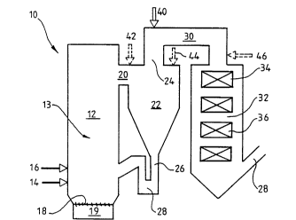
FIGURE 1 is schematic drawing of an exemplary circulating
fluidized bed system for reducing N2O in accordance with
the present invention; and
WO91/16575 PCT/FI91/00112
~ 2 ~ 8
g - .
FIGURES 2 and 3 are schematic drawings of other exemplary
embodiments.
A preferred embodiment of the present invention is shown
5 in FIGURE 1, where solid material is combusted in a cir-
~ culating fluidized bed reactor 10. The reactor includes a
combustion chamber 12 containing a fluidized bed of par-
ticles 13 with inlets 14, 16 for solid fuel material and
typically other solid material such as lime or limestone
10 for the reduction of SO2 in flue gases. Fluidizing air is
led into the combustion chamber through a bottom plate 18
from a windbox 19. The air is led into the reactor at
nearly an atmospheric pressure at a flow rate high enough
to fluidize the bed and entrain a portion of the solid
15 particles.
The combustion chamber has an outlet 20 for flue gases
containing entrained solid particles. The flue gases are
led to a cyclone separator 22 where solid bed particles
20 are separated from the gases. The cleaned gas is discharged
through a gas outlet opening duct 24 and the particles
separated from the gas are led downwards through a vertical
return duct 26 back into the lower part of the combustion
chamber. The return duct forms a bend 28 at its lower end
25 in front of the inlet to the combustion chamber.
The cleaned gas is led via the gas outlet opening 24 into
a gas passage 30 which connects the fluidized bed reactor
with a convection section 32. A superheater 34 is arranged
30 in the gas inlet zone of the convection section and other
heat transfer surfaces 36, downstream from the superheater.
Gas outlet 38 is arranged in the bottom part of the convec-
tion section.
. .
35 An additive inlet 40 for hydrogen radical providing additive
is arranged in the gas passage 30 connecting the cyclone
with the convection section. The inlet for additive is
disposed in the gas passage at a location close to the
WO91/16575 PCT/FI91/00112
.. .
~80~8 lO
cyclone gas outlet opening 24.
In operation, combustion is effected in a first combustion
stage in the combustion chamber at a relatively low tempera-
5 ture (e.g. when combusting coal at about 850C). At thistemperature a low NOX combustion is achieved and a maximum
sulphur capture with lime occurs. Flue gases containing
residual oxygen and N2O and entrained bed particles are
discharged through the gas outlet 20 into the cyclone 22.
lO Bed particles containing unreacted lime for sulphur capture
are separated from the flue gases in the cyclone and
recycled into the combustion chamber.
An additive, such as natural gas, is injected into the
15 still hot flue gas in the duct 30 through the additive inlet
(immediately after the cyclone). The natural gas to
some extent provides hydrogen radicals already at the flue
gas temperature, but due to the residual oxygen content in
the flue gases natural gas is combusted when entering the
20 flue gas passage 30, thus increasing the flue gas tempera-
ture in the flue gas passage to a still more favourable
level when considering hydrogen radical formation and N2O
reduction to N2. Alternatively, or additionally, 2 contain-
ing gas may be added in inlet 40 mixed with the additive.
The introduction of additive may additionally or alterna-
tively be accomplished through an inlet 42, shown as a
broken line in FIGURE l, in the short duct 2l connecting
the combustion chamber 12 and the cyclone 22. This inlet
30 42 may be used especially if the particle content of the
flue gases discharged from the combustion chamber, is
small. It is further possible to arrange an additive inlet
44 directly into the cyclone 22, into a particle lean
zone. The advantage of this arrangement is inherently good
35 mixing between flue gases and introduced additive in the
gas vortex in the cyclone.
The additive may also or alternatively be injected into
WO9!/16575 PCT/FI9l/00112
~ 11 2~8~
the convection section through an inlet 46 arranged im-
mediately upstream of the superheater 34. This arrangement
is advantageous if there are problems in getting enough
superheating steam.
~ Another embodiment of the present invention is shown in
FIGURE 2. In this embodiment heat exchange tubes 38, e.g.
a few rows of screen tubes, are disposed in a gas duct 30
after a cyclone, but before the duct enlargens into a
10 convection section 32.
An optimal location for an additive inlet 40 seems often
to be immediately after the screen tubes 38. Normally the
screen tubes are water cooled, but can in some applica-
15 tions be steam or air cooled. High temperatures in the gasduct can cause problems if the tubes are air or steam
cooled. The water tubes can be connected to other water/-
steam systems, e.g. the cooling system of a cooled cyclone,
in the fluidized bed reactor. If air cooled tubes are
20 used, the heated air can be used as combustion air. The
heated air can also be used to inject hydrogen radical
providing additive into the gas duct.
A heat exchanger arranged upstreams of the injection of
25 hydrogen radical providing additive is advantageous for
flattening the gas velocity profile in the gas duct. This
is useful because the flue gas from the cyclone exit may
have a skewed velocity profile.
30 The heat exchanger is further useful to control the flue
gas temperature so that the additive is injected at the
optimum temperature for maximum effectiveness. With the
heat exchanger the temperature can be regulated to an
optimal level. For each additive there is an optimal
35 temperature for maximum efficiency.
Still another embodiment of the present invention is shown
in FIGURE 3, where solid material is combusted in a pres-
WO91/16575 PCT/F191/00112
20806Y~ 12 ~ ~
surized circulating fluidized bed reactor 50. The pres-
surized flue gas is led through a cyclone 52, for separating
particles from the gas, and a convection section 54 into a
particle filter 56 for cleaning the pressurized flue gases.
5 The cleaned flue gas is led into a combustion chamber 58
immediately upstream of a gas turbine 60, where the flue
gas is expanded. In the combustion chamber 58 reduction of
N2O is accomplished by introducing additional fuel into
the flue gas through inlet 62 and combusting the fuel to
lO simultaneously increase the temperature of the flue gas.
In all embodiments it is necessary to adjust the amount of
additive introduced depending upon the type of additive,
fuel, fluidized bed reactor, position of injection, and a
15 wide variety of other factors.
While the invention has been described in connection with
what is presently considered to be the most practical and
preferred embodiment, it is to be understood that the
20 invention is not to be limited to the disclosed embodiment,
but on the contrary, is intended to cover various modifica-
tions and equivalent arrangements included within the
spirit and scope of the appended claims.