Note: Descriptions are shown in the official language in which they were submitted.
9 ~ ~ 203-610
(1263)
RETAINER FOR A COMBINED SURGICAL NEEDLE-SUTURE DEVICE
POSSESSING A NEEDI~ SHIE:LD WITH NEE~LE TIP STOP FEATURE
BACKGROUND_OF THE INVENTION
This invention relates to a retainer for a
combined surgical needle-suture device, also commonly
referred to as an "armed suture" or simply a "suture", as
part of a suture package. Retainers ~or sutures are known
from, inter alia, U.S. Patent Nos. ~,363,751; 3,444,944;
3,613,878; 3,759,376; 3,857,4~4; 3,939,969; 3,g~1,261;
~o 3,972,~18; 3,985,277; 4,063,638; 4,089,409; 4,120,395;
- 4,135,623; 4,192,420; 4,249,656; 4,2~3,563; 4,284,194;
4,406,363; 4,412,614; 4,413,727; 4,4~7,109; 4,4~3,437;
4,491,218; 4,496,045; 4,533,0~1; 4,555,016; 4,572,363;
4,574,948; 4,574,957; ~,615,435; 4,708,241; 4,813,537;
4,884,681; 4,887,710; 4,896,767; 4,961,498; and~ 4,967,902.
As an essential component of a suture package, the
suture retainer should possess good storing qualities,
provide safety in handling and permit ready access to, and
removal of, the stored sutures.
SUMMARY OF THE INVENTION
By way of meeting the foregoing criteria, there is
; provided in accordance with this invention a retainer for a
combined surgical needle-suture device, the retaine~-
comprising
a~ a base panel for retaining at least one
surgical neadle of a combined surgical needle-suture device;
and,
b) a needle shield mounted upon the base panel,
the needle shield possessing a stop for retaining the tip of
the needle.
2~8~
--2--
1 The ~top feature of the needle shield effectively
prevents accidental puncture by a stored needle and permits
rapid access and removal of an armed suture when desired.
BRIEF DESCRIPTION OF THE DRAWINGS
Figs. 1 and 2 are perspective views of embodiments
of a needle shield in accordance with the present invention;
Figs. 3 and 4 are perspective views of the obverse
and reverse sides, respectively, o~ an armed suture retainer
card with the needle shield of Fig. 1 mounted thereon;
Fig. 5 is a top plan view of a suture package,
including its outer breather package, suitable for packaging
the armed suture retainer of Figs. 3 and 4; and,
Fig. 6 is a top plan view of the suture package of
Fig. 5 removed from the breather package and opened for
partially exposure of its armed suture contents.
DESCRIPTION OF THE PREFERRED EMBODIMENTS
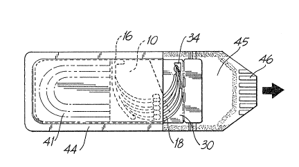
As shown in Figs. 1 and 2, needle shields 10 and
10' are each fabricated from a suitably stiff material,
preferably a transparent thermoplastic resin such as
polyethylene terephthalate. The needle shields are
conveniently manufactured from sheets of thermoplastic resin
by such known and conventional processes as thermoforming.
Needle shield 10 possesses top and bottom edges 11
and 12, respectively, and flanged parallel lateral edges 13
and 14, respectively, by which the needle s~ield grips side
edges 31 and 32 of retainer base panel 30 as shown in Figs.
3 and 4. An arcuate stop, or wall, 16 projecting upwardly
from surface 15 of needle shield lO retains the sharp tips
-3- 2~ 7~
of needle components 18 (as sho~n in Fig. 3) preventing the
tip from causing accidental puncture of front panel 43 of
peel-open suture package 40 (shown in Figs. 5 and 6).
Advantageously, stop 16 continues a short distance up
lateral edge 13 to provide additional security against
accidental puncture. By way of maintaining ne~dle
components 18 in a neat array upon surface 15 of needle
shield 10, the surface is provided with a series of ~uts
defining tabs 17 which, when displaced upwardly from surface
15, provide elements for securing individual needles 18 in
place. Needle securing means other than tabs 17 can, of
course, be utilized, eOg., a series of approximately
parallel "bumps: with a needle snap-~itted therebetween (not
shown~.
Needle shield 10', like needle shield 10,
possesses flanged lateral edges 13' and 14' by which the
needle shield grips the side edges of an armed suture
retainer panel. Stop 16l is an integral elament of pocket
1~ and like stop 16 of needle shield 10, retains the tip of
a needle thereby preventing accidental puncture of the armed
suture package. HoweYer, unlike needle shield 10 in which
the needles lie upon surface 15 of the shield, in needle
shield 10', the stored needles are retained within pocket
19, i.e., beneath surface 15' o~ the shield.
As sho~ in Figs. 3 and 4 and in dotted outline in
Fig. 6, the general appearance of retainer base panel 30 is
that of a flat, relatively stiff panel whose longest sides
31 and 32 are parallel to each other to permit needle shield
10 or 10' to be slid onto the retainer during the packaging
operation. Retainer 30 can be constructed ~rom any o~
several different t~pes of materials including various kinds
,
~4~ ~8~8
1 of plastics, paper-foil laminate, etc. Retainer base panel
30 is more fully described, together with peel-open foil
package 40 of Figs. 5 and 6 for acco~modating the loaded
retainer, in pending U.S. patent application Serial No.
07/566,263, filed August 13, 1990 the contents of which are
incorporated by reference herein. A similar retainer base
panel which is also suitable for use herein is described in
pending U.S. patent application Serial No. 07/601,019, filed
October 18, 1991 the contents of which are incorporated by
reference herein.
As shown in Figs. 3 and 4, naedle shield 10 has
been mounted in place by being slid on'co retainer base panel
30 in the direction indicated by the arrow. A number of
armed sutures are secured in place upon retainer base panel
1S 30, their curved needle components 18 lying flat upon a
portion of obverse side 33 of the base panel and a portion
of surface 15 of needle shield 10 with their suture
components 20 extending through triangular shaped aperture
34 to reverse side 35 of the base panel where they occupy
coiled passageway 36. The sutures can be dxawn into coiled
` passageway 36 by applying a vacuum through orifice 37
- positioned at the far end of the passageway. Under the
influence of the vacuum, the sutures quickly occupy the
passageway.
The fully loaded armed suture retainer of Figs. 3
and 4 is conveniently packaged in peel-open metal foil
suture package 40 of Fig. 5 shown in its outer breather
package 50 following sterilization and sealing. Suture
- package 40 comprises an envelope 41 made up of front panel
42 joined to a rear panel (not shown) along common edges 44
employing any known and conventional adhesi~e. ~eelable
3S
_5_ 2 ~
1 closure flap 45 completes package 40 and is advantageously
provided with a knurled or embossed trapezoidally configured
edge 46 to facilitate gripping. The material of
construction of the front and rear panels and the closure
flap i6 one which prevents or greatly impedes the
transmission o~ moisture therethrough. In the embodiment
shown, the walls and the closure flap are of laminate
construction of a known type in which an alumi~um foil is
faced on its interior side with a polyolefin ~ilm such as
polyethylene film. The laminate can Yary in thickne~s from
a~out 3 to about 5 mils and pre~erably from about 3.5 to
about 4.5 mils.
Retainer base panel 30 is provided with an
- extension panel 38 which is adhesively secured to the
undersurface of closure flap 45 such that when the closure
flap is pulled open, it will not readily completely separate
from pacXage 40 where it might otherwise litter the
operating area. To remove an armed suture from opened
suture package 30, the shank of a needle is grasped by a
needle gripper and pulled away from the package, usually in
a direction which is more or less in the plane of the
package.
Outer breather pacXage 50 (Fig. 5) can be of known
and conventional structure in which a gas-impermeable clear
plastic ~heet is heat sealed around its top and bottom edges
51 and 52 and its long tudinal edges 53 and 54 to a gas
permeable but sterile-secure backing sheet such as a web of
spun-bonded polyolefin fiber, e.g.~ DuPont's Tyvek In an
improvement in this type o~ breather pouch which is
especially suitable for use with the present invention, the
fibrous backing sheet is provided with a strip of release
;
.
-6- 2~ 7~
1 agent, e.g., of a water-based adhesive which dries to a non-
tacky finish, along its longitudinal edges which effectively
eliminates the possibility o~ fiber-pull in the sheet when
the clear plastic sheet is stripped away. Thus, as the top
seal is peeled apart, the release agent along the
longitudinal edges facilitates opening of the package and
substantially eliminates the possibility of fiber-pull along
the longitudinal edges by providing a pull-~orce which is
substantially less than the force required to separate the
fibers in the backing sheet from themselv~sO Also, as a
result of the application of the release agent to the
ongitudinal edges, the pull force at the top and bottom
seals required to separate the plastic layer from the
fibrous backing sheet is slightly greater than the pull
force required to separate the two layers at the side edges.
Thus, after the initial pull separates the sheets at the top
seal, it is easier to open the rest of the package by
pulling the sheets apart since the force required to
separate the sheets at the longitudinal edges is less than
the force required to separate the initial top heat seal.
The i~proved breather pouch can be manufactured on
an apparatus which feeds a web of fibrous ~acking material,
e.g., Tyvek, having at least two continuous longitudinally
directed strips of release agent material applied thereon at
regular intervals starting at the first edge of the ~eb and
terminating at the second longitudinal ed~e. The apparatus
feeds the web of Tyvek material and a web o~ plastic
material, preferably polyethylene, to a position to enclose
suture packayes placed in rows between the plastic and Tyvek
layers. This assembly is then fed to a heat seal device
which simultaneously provides transverse and longitudinal
1 heat seals to seal the suture packages between the two
layers. Preferably, the plastic web is vacuum formed to
provide recesses or pockets to accept the suture packages
thereon. The Tyvek then overlays the plastic ~nd ~uture
packages and the heat seal device seals about the recesses.
Alternately, the release agent material may be positioned in
longitudinal strips between the tyvek and pla~tic layers
prior to the heat sealing step, so that the heat seal is
through the release agent between the two layers of
material. It is preferred, however, that the release agent
material be applied directly to the Tyvek layer.
A heat seal platen is applied to the webs to form
the seals for adjacent packagesO The asse~bly is then
advanced to a cutter mechanism which cuts the pouches just
below the transverse seal to form the bottom of one package
and along the longitudinal seals, while ensuring that the
top edge seals of the individual packages include the
gripping tab formed for each package which facilitates
separation of the plastic layer from the Tyvek layer to open
the pouch.
It will be thus seen that the objects set forth
above, among those made apparent from the preceding
description, are efficiently attained, and since certain
changes can be made in the above construction and different
embodiments of the invention could be made without departing
from the scope thereof, it is intended that all matter
~ contained in the above description or shown in the
. accompanying drawing shall be interpreted as illustrative
and not in a limiting sense.
"
:;