Language selection

Search

Patent 2080998 Summary

Third-party information liability

Some of the information on this Web page has been provided by external sources. The Government of Canada is not responsible for the accuracy, reliability or currency of the information supplied by external sources. Users wishing to rely upon this information should consult directly with the source of the information. Content provided by external sources is not subject to official languages, privacy and accessibility requirements.

Claims and Abstract availability

Any discrepancies in the text and image of the Claims and Abstract are due to differing posting times. Text of the Claims and Abstract are posted:

  • At the time the application is open to public inspection;
  • At the time of issue of the patent (grant).
(12) Patent: (11) CA 2080998
(54) English Title: METHOD AND APPARATUS FOR THE LOCAL FORMING OF BRITTLE MATERIAL
(54) French Title: METHODE ET APPAREIL DE FACONNAGE LOCALISE DE MATERIAU CASSANT
Status: Expired and beyond the Period of Reversal
Bibliographic Data
(51) International Patent Classification (IPC):
  • B21K 25/00 (2006.01)
  • B21D 39/03 (2006.01)
(72) Inventors :
  • DOBRIKOW, MATTHIAS (Germany)
(73) Owners :
  • ECKOLD GMBH & CO. KG
(71) Applicants :
  • ECKOLD GMBH & CO. KG (Germany)
(74) Agent: SMART & BIGGAR LP
(74) Associate agent:
(45) Issued: 1999-09-07
(22) Filed Date: 1992-10-20
(41) Open to Public Inspection: 1993-05-14
Examination requested: 1996-08-28
Availability of licence: N/A
Dedicated to the Public: N/A
(25) Language of filing: English

Patent Cooperation Treaty (PCT): No

(30) Application Priority Data:
Application No. Country/Territory Date
G 91 14 122.2 (Germany) 1991-11-13

Abstracts

English Abstract


Method for the local forming of material tending
towards brittle fracture, such as certain aluminium
alloys, in which during the forming tensile loads are
exerted on the material, such as for example in joggle
joining. brittle fracture is avoided if the material is
subjected to a pressure load in the region which is to
be formed.


Claims

Note: Claims are shown in the official language in which they were submitted.

THE EMBODIMENTS OF THE INVENTION IN WHICH AN EXCLUSIVE
PROPERTY OR PRIVILEGE IS CLAIMED ARE DEFINED AS FOLLOWS:
1. A method of joining a first metal sheet to a second
metal sheet, at least one of said sheets being made of brittle
material, the method comprising the steps:
placing the two sheets together and between a punch
member and an anvil member having a chamfer and being
surrounded by a die member, said anvil member being adapted to
be displaced from an initial position where it extends beyond
a die surface to an end position within said die member
thereby defining a cavity, said anvil member being biased
towards said initial position by means of a spring;
displacing said sheets and said anvil member towards
said end position by pressing said punch member against said
sheets until the sheet facing the anvil member abuts said die
surface whereby bias force produced by said spring increases
to a first predetermined value so as to improve ductility of
said brittle material;
displacing sheet material between said punch member
and said anvil member into said die cavity whereby said bias
force produced by said spring increases to a second
predetermined value; and
when the anvil member has reached its end position;
compressing sheet material within said die cavity between said
punch member and said anvil member to cause cold flow of said
material into a space between an inner die member wall and
said anvil chamfer.
-4-

2. A method as in claim 1, wherein the first and second
metal sheets are each composed of a brittle aluminum alloy.
3. A method for local reshaping of material by tensile
loading, wherein the material is at the same time subjected to
a pressure loading, characterised in that for the reshaping of
brittle material, a high pressure loading, which is however
within the elastic range, is applied before the start of the
tensile deformation.
4. A method according to claim 3 in which the material
is a brittle aluminum alloy.
5. A method according to claim 3 in which the material
is in the form of metal sheets which are clinch joined
together.
6. A method according to claim 5, wherein the metal
sheets to be joined are subjected to a pressure loading in a
direction perpendicular to their surface.
-5-

Description

Note: Descriptions are shown in the official language in which they were submitted.


~ 4~ ~ ~~ ~~~ ,.~~~ ~'~~ ~~
.,
Method and apparatus for the local formincr of brittle
material
The invention relates to a method for the local
forming of brittle material and to an apparatus for
applying said method.
The invention relates particularly, but not
exclusively, to the joining of metal sheets by joggle
joining techniques. i~Iany such methods are known.
Reference raay be made as an example to specifications
EP-A-215,449, US-A-4,757,609 and US-A-5,046,22. A
common feature of all these methods is that metal sheets
are laid flat one upon the other and that material in
both sheets is locally joggled to one side, care being
taken to ensure that the material of the sheets ire the
joggled slug is clamped together frictionally and
positively.
This technique has been adopted as an economical
production method in many fields, for example in motor
vehicle manufacture, in air conditioning and in machine
construction when mass production is required.
These joining methods can be applied to many
metals and plastics materials. However, it has not
hitherto been possible to join brittle materials, such as
for example certain aluminium alloys, by such techniques,
because their strainability is insufficient; as a general
rule such brittle materials can undergo non-cutting
forming only within a narrow range.
The object of the invention is to indicate a
method which permits greater deformation of brittle
materials than was possible hitherto. In particular, the
joggle joining of sheets of brittle aluminium alloys is
to be made possible.
The solution, provided by the invention, to this
problem is given a.n Patent Claim 1; the claims dependent
on the latter define preferred applications of the method
and apparatuses for applying it. ,
It has hitherto not been known what phenomena
underlie the empirically established fact that brittle

~~~0~~'s'
fractures do not occur in forming carried out under an
additional pressure load, whereas the same degree of
forming without such a pressure load leads to brittle
fracture. The pressure load must of course remain within
the elastic range of the stress-strain diagram, and is
compensated in the forming, in which of course the entire
elastic range must necessarily be passed through before
plastic deformation occurs. This will have to be
explained by further investigations.
Known joggle joining tools of the types mentioned
in the introduction generally comprise a die bounding a
cavity into which the sheet material is deformed by means
of a punch; an anvil forming the die bottom is disposed
opposite the working surface of the punch. In a very
simple apparatus for applying the method according to the
invention, the sheet material is placed under a pressure
load by subjecting the anvil to an appropriate spring
preload in the direction opposite to the working stroke
of the punch. In this connection it may be observed that
joggle joining tools are known in which the anvil is
spring preloaded in the same direction. Thus,
US-A-3,771,216 discloses an arrangement of this kind in
which the anvil and spring combination serves' as an
ejector intended to remove the joint from the die.
US-A-4,58,753 discloses a die in which, in the position
of rest, the anvil projects beyond tkae edge of the die
under spring preloading; here, the projecting portion of
the anvil serves as centring means intended to position
a pre-perforated sheet in relation to the die and the
punch. In both cases, however, the force produced by the
spring is some orders of mac~nztude less than the forces
which are to be applied in accordance with the invention.
A simple exemplary embodiment of an apparatus for
applying the method according to the invention is
illustrated schematically in the accompanying drawings
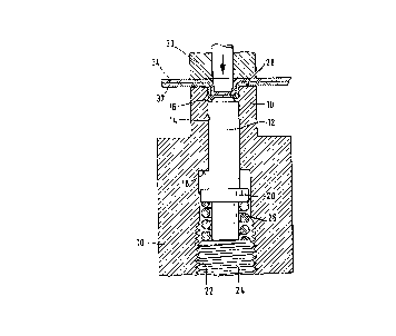
. and explained more fully below. Figure 1 of the drawings
shows the position of the components (for the sake of
simplicity given a circular cross-section) at the

3
begining of the joining operation, and Figure 2 shows
them at the end of the joining operation, in axial
section in each case.
An anvil 12 is slidably mounted in a die 10,
being guided in a bore 14 in the latter. The top portion
of the bore bounds the cavity 16 into which the material
is deformed (see Figure 2). A shoulder 18 serves as top
stop for a collar 20 formed on the anvil. Tn the
adjoining bottom part of the die bore, whch has a larger
diameter, a screw thread 22 is cut, into which a bottom
stop 24 is screwed. Between the latter and the collar 20
of the anvil, a powerful spring, in the present case a
helical compression spring 26, is clamped and preloads
the anvil into its top end position shown in Figure 1.
l5 It can be seen that, before the joining operation, the
anvil projects out beyond the working end face 28 of the
die and is chamfered around its edge.
The punch 30, driven for example by a hydraulic
unit, at first clamps the sheets 32, 34, which are to be
joined together, between its working face and the anvil,
so that the. sheet material is subjected to a pressure
load corresponding to the preloading by the spring 26.
During the joining operation this pressure load is first
increased until the anvil is forced back into the die
bore, while surprisingly no fracture of material occurs.
Finally, the anvil rests on the bottom stop and the punch
presses material into the space left free by the chamfer
on the anvil, so that the sheets are clamped together.
It can be seen that here the pressure load acts not only
before but also during the joggling.
In order to facilitate extraction, the die may be
hinged so that it can be opened and may be undercut in
the region of the cavity - all of which is already known
in joining tools but may also~be advantageously applied
here.

Representative Drawing
A single figure which represents the drawing illustrating the invention.
Administrative Status

2024-08-01:As part of the Next Generation Patents (NGP) transition, the Canadian Patents Database (CPD) now contains a more detailed Event History, which replicates the Event Log of our new back-office solution.

Please note that "Inactive:" events refers to events no longer in use in our new back-office solution.

For a clearer understanding of the status of the application/patent presented on this page, the site Disclaimer , as well as the definitions for Patent , Event History , Maintenance Fee  and Payment History  should be consulted.

Event History

Description Date
Inactive: IPC from MCD 2006-03-11
Time Limit for Reversal Expired 2000-10-20
Letter Sent 1999-10-20
Grant by Issuance 1999-09-07
Inactive: Cover page published 1999-09-06
Inactive: Final fee received 1999-05-31
Pre-grant 1999-05-31
Letter Sent 1999-03-08
Notice of Allowance is Issued 1999-03-08
Inactive: Status info is complete as of Log entry date 1999-03-04
Inactive: Application prosecuted on TS as of Log entry date 1999-03-04
Inactive: Approved for allowance (AFA) 1999-02-03
Request for Examination Requirements Determined Compliant 1996-08-28
All Requirements for Examination Determined Compliant 1996-08-28
Application Published (Open to Public Inspection) 1993-05-14

Abandonment History

There is no abandonment history.

Maintenance Fee

The last payment was received on 1998-09-17

Note : If the full payment has not been received on or before the date indicated, a further fee may be required which may be one of the following

  • the reinstatement fee;
  • the late payment fee; or
  • additional fee to reverse deemed expiry.

Patent fees are adjusted on the 1st of January every year. The amounts above are the current amounts if received by December 31 of the current year.
Please refer to the CIPO Patent Fees web page to see all current fee amounts.

Fee History

Fee Type Anniversary Year Due Date Paid Date
MF (application, 5th anniv.) - small 05 1997-10-20 1997-09-25
MF (application, 6th anniv.) - small 06 1998-10-20 1998-09-17
Final fee - standard 1999-05-31
Owners on Record

Note: Records showing the ownership history in alphabetical order.

Current Owners on Record
ECKOLD GMBH & CO. KG
Past Owners on Record
MATTHIAS DOBRIKOW
Past Owners that do not appear in the "Owners on Record" listing will appear in other documentation within the application.
Documents

To view selected files, please enter reCAPTCHA code :


To view images, click a link in the Document Description column. To download the documents, select one or more checkboxes in the first column and then click the "Download Selected in PDF format (Zip Archive)" or the "Download Selected as Single PDF" button.

List of published and non-published patent-specific documents on the CPD .

If you have any difficulty accessing content, you can call the Client Service Centre at 1-866-997-1936 or send them an e-mail at CIPO Client Service Centre.


Document
Description 
Date
(yyyy-mm-dd) 
Number of pages   Size of Image (KB) 
Representative drawing 1998-09-08 1 30
Representative drawing 1999-08-31 1 16
Abstract 1993-11-19 1 13
Claims 1993-11-19 2 54
Drawings 1993-11-19 2 68
Description 1993-11-19 3 148
Claims 1999-01-14 2 64
Commissioner's Notice - Application Found Allowable 1999-03-07 1 164
Maintenance Fee Notice 1999-11-16 1 178
Correspondence 1999-05-30 1 33
Fees 1996-09-19 1 69
Fees 1995-09-20 1 67
Fees 1994-09-15 1 75
Prosecution correspondence 1996-08-27 2 61
Courtesy - Office Letter 1993-05-24 1 16
Courtesy - Office Letter 1996-08-27 1 38