Sélection de la langue

Search

Sommaire du brevet 2080998 

Énoncé de désistement de responsabilité concernant l'information provenant de tiers

Une partie des informations de ce site Web a été fournie par des sources externes. Le gouvernement du Canada n'assume aucune responsabilité concernant la précision, l'actualité ou la fiabilité des informations fournies par les sources externes. Les utilisateurs qui désirent employer cette information devraient consulter directement la source des informations. Le contenu fourni par les sources externes n'est pas assujetti aux exigences sur les langues officielles, la protection des renseignements personnels et l'accessibilité.

Disponibilité de l'Abrégé et des Revendications

L'apparition de différences dans le texte et l'image des Revendications et de l'Abrégé dépend du moment auquel le document est publié. Les textes des Revendications et de l'Abrégé sont affichés :

  • lorsque la demande peut être examinée par le public;
  • lorsque le brevet est émis (délivrance).
(12) Brevet: (11) CA 2080998
(54) Titre français: METHODE ET APPAREIL DE FACONNAGE LOCALISE DE MATERIAU CASSANT
(54) Titre anglais: METHOD AND APPARATUS FOR THE LOCAL FORMING OF BRITTLE MATERIAL
Statut: Périmé et au-delà du délai pour l’annulation
Données bibliographiques
(51) Classification internationale des brevets (CIB):
  • B21K 25/00 (2006.01)
  • B21D 39/03 (2006.01)
(72) Inventeurs :
  • DOBRIKOW, MATTHIAS (Allemagne)
(73) Titulaires :
  • ECKOLD GMBH & CO. KG
(71) Demandeurs :
  • ECKOLD GMBH & CO. KG (Allemagne)
(74) Agent: SMART & BIGGAR LP
(74) Co-agent:
(45) Délivré: 1999-09-07
(22) Date de dépôt: 1992-10-20
(41) Mise à la disponibilité du public: 1993-05-14
Requête d'examen: 1996-08-28
Licence disponible: S.O.
Cédé au domaine public: S.O.
(25) Langue des documents déposés: Anglais

Traité de coopération en matière de brevets (PCT): Non

(30) Données de priorité de la demande:
Numéro de la demande Pays / territoire Date
G 91 14 122.2 (Allemagne) 1991-11-13

Abrégés

Abrégé anglais


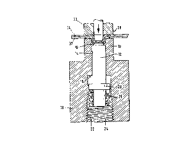
Method for the local forming of material tending
towards brittle fracture, such as certain aluminium
alloys, in which during the forming tensile loads are
exerted on the material, such as for example in joggle
joining. brittle fracture is avoided if the material is
subjected to a pressure load in the region which is to
be formed.

Revendications

Note : Les revendications sont présentées dans la langue officielle dans laquelle elles ont été soumises.


THE EMBODIMENTS OF THE INVENTION IN WHICH AN EXCLUSIVE
PROPERTY OR PRIVILEGE IS CLAIMED ARE DEFINED AS FOLLOWS:
1. A method of joining a first metal sheet to a second
metal sheet, at least one of said sheets being made of brittle
material, the method comprising the steps:
placing the two sheets together and between a punch
member and an anvil member having a chamfer and being
surrounded by a die member, said anvil member being adapted to
be displaced from an initial position where it extends beyond
a die surface to an end position within said die member
thereby defining a cavity, said anvil member being biased
towards said initial position by means of a spring;
displacing said sheets and said anvil member towards
said end position by pressing said punch member against said
sheets until the sheet facing the anvil member abuts said die
surface whereby bias force produced by said spring increases
to a first predetermined value so as to improve ductility of
said brittle material;
displacing sheet material between said punch member
and said anvil member into said die cavity whereby said bias
force produced by said spring increases to a second
predetermined value; and
when the anvil member has reached its end position;
compressing sheet material within said die cavity between said
punch member and said anvil member to cause cold flow of said
material into a space between an inner die member wall and
said anvil chamfer.
-4-

2. A method as in claim 1, wherein the first and second
metal sheets are each composed of a brittle aluminum alloy.
3. A method for local reshaping of material by tensile
loading, wherein the material is at the same time subjected to
a pressure loading, characterised in that for the reshaping of
brittle material, a high pressure loading, which is however
within the elastic range, is applied before the start of the
tensile deformation.
4. A method according to claim 3 in which the material
is a brittle aluminum alloy.
5. A method according to claim 3 in which the material
is in the form of metal sheets which are clinch joined
together.
6. A method according to claim 5, wherein the metal
sheets to be joined are subjected to a pressure loading in a
direction perpendicular to their surface.
-5-

Description

Note : Les descriptions sont présentées dans la langue officielle dans laquelle elles ont été soumises.


~ 4~ ~ ~~ ~~~ ,.~~~ ~'~~ ~~
.,
Method and apparatus for the local formincr of brittle
material
The invention relates to a method for the local
forming of brittle material and to an apparatus for
applying said method.
The invention relates particularly, but not
exclusively, to the joining of metal sheets by joggle
joining techniques. i~Iany such methods are known.
Reference raay be made as an example to specifications
EP-A-215,449, US-A-4,757,609 and US-A-5,046,22. A
common feature of all these methods is that metal sheets
are laid flat one upon the other and that material in
both sheets is locally joggled to one side, care being
taken to ensure that the material of the sheets ire the
joggled slug is clamped together frictionally and
positively.
This technique has been adopted as an economical
production method in many fields, for example in motor
vehicle manufacture, in air conditioning and in machine
construction when mass production is required.
These joining methods can be applied to many
metals and plastics materials. However, it has not
hitherto been possible to join brittle materials, such as
for example certain aluminium alloys, by such techniques,
because their strainability is insufficient; as a general
rule such brittle materials can undergo non-cutting
forming only within a narrow range.
The object of the invention is to indicate a
method which permits greater deformation of brittle
materials than was possible hitherto. In particular, the
joggle joining of sheets of brittle aluminium alloys is
to be made possible.
The solution, provided by the invention, to this
problem is given a.n Patent Claim 1; the claims dependent
on the latter define preferred applications of the method
and apparatuses for applying it. ,
It has hitherto not been known what phenomena
underlie the empirically established fact that brittle

~~~0~~'s'
fractures do not occur in forming carried out under an
additional pressure load, whereas the same degree of
forming without such a pressure load leads to brittle
fracture. The pressure load must of course remain within
the elastic range of the stress-strain diagram, and is
compensated in the forming, in which of course the entire
elastic range must necessarily be passed through before
plastic deformation occurs. This will have to be
explained by further investigations.
Known joggle joining tools of the types mentioned
in the introduction generally comprise a die bounding a
cavity into which the sheet material is deformed by means
of a punch; an anvil forming the die bottom is disposed
opposite the working surface of the punch. In a very
simple apparatus for applying the method according to the
invention, the sheet material is placed under a pressure
load by subjecting the anvil to an appropriate spring
preload in the direction opposite to the working stroke
of the punch. In this connection it may be observed that
joggle joining tools are known in which the anvil is
spring preloaded in the same direction. Thus,
US-A-3,771,216 discloses an arrangement of this kind in
which the anvil and spring combination serves' as an
ejector intended to remove the joint from the die.
US-A-4,58,753 discloses a die in which, in the position
of rest, the anvil projects beyond tkae edge of the die
under spring preloading; here, the projecting portion of
the anvil serves as centring means intended to position
a pre-perforated sheet in relation to the die and the
punch. In both cases, however, the force produced by the
spring is some orders of mac~nztude less than the forces
which are to be applied in accordance with the invention.
A simple exemplary embodiment of an apparatus for
applying the method according to the invention is
illustrated schematically in the accompanying drawings
. and explained more fully below. Figure 1 of the drawings
shows the position of the components (for the sake of
simplicity given a circular cross-section) at the

3
begining of the joining operation, and Figure 2 shows
them at the end of the joining operation, in axial
section in each case.
An anvil 12 is slidably mounted in a die 10,
being guided in a bore 14 in the latter. The top portion
of the bore bounds the cavity 16 into which the material
is deformed (see Figure 2). A shoulder 18 serves as top
stop for a collar 20 formed on the anvil. Tn the
adjoining bottom part of the die bore, whch has a larger
diameter, a screw thread 22 is cut, into which a bottom
stop 24 is screwed. Between the latter and the collar 20
of the anvil, a powerful spring, in the present case a
helical compression spring 26, is clamped and preloads
the anvil into its top end position shown in Figure 1.
l5 It can be seen that, before the joining operation, the
anvil projects out beyond the working end face 28 of the
die and is chamfered around its edge.
The punch 30, driven for example by a hydraulic
unit, at first clamps the sheets 32, 34, which are to be
joined together, between its working face and the anvil,
so that the. sheet material is subjected to a pressure
load corresponding to the preloading by the spring 26.
During the joining operation this pressure load is first
increased until the anvil is forced back into the die
bore, while surprisingly no fracture of material occurs.
Finally, the anvil rests on the bottom stop and the punch
presses material into the space left free by the chamfer
on the anvil, so that the sheets are clamped together.
It can be seen that here the pressure load acts not only
before but also during the joggling.
In order to facilitate extraction, the die may be
hinged so that it can be opened and may be undercut in
the region of the cavity - all of which is already known
in joining tools but may also~be advantageously applied
here.

Dessin représentatif
Une figure unique qui représente un dessin illustrant l'invention.
États administratifs

2024-08-01 : Dans le cadre de la transition vers les Brevets de nouvelle génération (BNG), la base de données sur les brevets canadiens (BDBC) contient désormais un Historique d'événement plus détaillé, qui reproduit le Journal des événements de notre nouvelle solution interne.

Veuillez noter que les événements débutant par « Inactive : » se réfèrent à des événements qui ne sont plus utilisés dans notre nouvelle solution interne.

Pour une meilleure compréhension de l'état de la demande ou brevet qui figure sur cette page, la rubrique Mise en garde , et les descriptions de Brevet , Historique d'événement , Taxes périodiques et Historique des paiements devraient être consultées.

Historique d'événement

Description Date
Inactive : CIB de MCD 2006-03-11
Le délai pour l'annulation est expiré 2000-10-20
Lettre envoyée 1999-10-20
Accordé par délivrance 1999-09-07
Inactive : Page couverture publiée 1999-09-06
Inactive : Taxe finale reçue 1999-05-31
Préoctroi 1999-05-31
Lettre envoyée 1999-03-08
Un avis d'acceptation est envoyé 1999-03-08
Inactive : Renseign. sur l'état - Complets dès date d'ent. journ. 1999-03-04
Inactive : Dem. traitée sur TS dès date d'ent. journal 1999-03-04
Inactive : Approuvée aux fins d'acceptation (AFA) 1999-02-03
Exigences pour une requête d'examen - jugée conforme 1996-08-28
Toutes les exigences pour l'examen - jugée conforme 1996-08-28
Demande publiée (accessible au public) 1993-05-14

Historique d'abandonnement

Il n'y a pas d'historique d'abandonnement

Taxes périodiques

Le dernier paiement a été reçu le 1998-09-17

Avis : Si le paiement en totalité n'a pas été reçu au plus tard à la date indiquée, une taxe supplémentaire peut être imposée, soit une des taxes suivantes :

  • taxe de rétablissement ;
  • taxe pour paiement en souffrance ; ou
  • taxe additionnelle pour le renversement d'une péremption réputée.

Les taxes sur les brevets sont ajustées au 1er janvier de chaque année. Les montants ci-dessus sont les montants actuels s'ils sont reçus au plus tard le 31 décembre de l'année en cours.
Veuillez vous référer à la page web des taxes sur les brevets de l'OPIC pour voir tous les montants actuels des taxes.

Historique des taxes

Type de taxes Anniversaire Échéance Date payée
TM (demande, 5e anniv.) - petite 05 1997-10-20 1997-09-25
TM (demande, 6e anniv.) - petite 06 1998-10-20 1998-09-17
Taxe finale - générale 1999-05-31
Titulaires au dossier

Les titulaires actuels et antérieures au dossier sont affichés en ordre alphabétique.

Titulaires actuels au dossier
ECKOLD GMBH & CO. KG
Titulaires antérieures au dossier
MATTHIAS DOBRIKOW
Les propriétaires antérieurs qui ne figurent pas dans la liste des « Propriétaires au dossier » apparaîtront dans d'autres documents au dossier.
Documents

Pour visionner les fichiers sélectionnés, entrer le code reCAPTCHA :


Pour visualiser une image, cliquer sur un lien dans la colonne description du document. Pour télécharger l'image (les images), cliquer l'une ou plusieurs cases à cocher dans la première colonne et ensuite cliquer sur le bouton "Télécharger sélection en format PDF (archive Zip)" ou le bouton "Télécharger sélection (en un fichier PDF fusionné)".

Liste des documents de brevet publiés et non publiés sur la BDBC .

Si vous avez des difficultés à accéder au contenu, veuillez communiquer avec le Centre de services à la clientèle au 1-866-997-1936, ou envoyer un courriel au Centre de service à la clientèle de l'OPIC.


Description du
Document 
Date
(aaaa-mm-jj) 
Nombre de pages   Taille de l'image (Ko) 
Dessin représentatif 1998-09-08 1 30
Dessin représentatif 1999-08-31 1 16
Abrégé 1993-11-19 1 13
Revendications 1993-11-19 2 54
Dessins 1993-11-19 2 68
Description 1993-11-19 3 148
Revendications 1999-01-14 2 64
Avis du commissaire - Demande jugée acceptable 1999-03-07 1 164
Avis concernant la taxe de maintien 1999-11-16 1 178
Correspondance 1999-05-30 1 33
Taxes 1996-09-19 1 69
Taxes 1995-09-20 1 67
Taxes 1994-09-15 1 75
Correspondance de la poursuite 1996-08-27 2 61
Courtoisie - Lettre du bureau 1993-05-24 1 16
Courtoisie - Lettre du bureau 1996-08-27 1 38