Language selection

Search

Patent 2081060 Summary

Third-party information liability

Some of the information on this Web page has been provided by external sources. The Government of Canada is not responsible for the accuracy, reliability or currency of the information supplied by external sources. Users wishing to rely upon this information should consult directly with the source of the information. Content provided by external sources is not subject to official languages, privacy and accessibility requirements.

Claims and Abstract availability

Any discrepancies in the text and image of the Claims and Abstract are due to differing posting times. Text of the Claims and Abstract are posted:

  • At the time the application is open to public inspection;
  • At the time of issue of the patent (grant).
(12) Patent: (11) CA 2081060
(54) English Title: SQUEEZE PACKAGE WHICH CAN BE INVERTED TO DISPENSE LIQUIDS
(54) French Title: FLACON PRESSABLE A COUVERTURE PAR INVERSION DU FLACON
Status: Expired and beyond the Period of Reversal
Bibliographic Data
(51) International Patent Classification (IPC):
  • B65D 50/06 (2006.01)
  • B65D 37/00 (2006.01)
  • B65D 47/06 (2006.01)
  • B65D 85/00 (2006.01)
(72) Inventors :
  • KRALL, THOMAS J. (United States of America)
(73) Owners :
  • OWENS-ILLINOIS PLASTIC PRODUCTS INC.
(71) Applicants :
  • OWENS-ILLINOIS PLASTIC PRODUCTS INC. (United States of America)
(74) Agent: GOWLING WLG (CANADA) LLP
(74) Associate agent:
(45) Issued: 2000-12-19
(22) Filed Date: 1992-10-21
(41) Open to Public Inspection: 1993-04-22
Examination requested: 1999-09-20
Availability of licence: N/A
Dedicated to the Public: N/A
(25) Language of filing: English

Patent Cooperation Treaty (PCT): No

(30) Application Priority Data:
Application No. Country/Territory Date
779,700 (United States of America) 1991-10-21

Abstracts

English Abstract


A squeeze package such as a toilet bowl cleaner bottle comprising a plastic
container having an open neck defining a first opening, a second laterally
extended
opening on the neck defining a second opening and a closure mounted on the
neck
and movable from a first position and includes a portion extending into said
first
opening and providing a seal isolating the second opening from the contents of
the
container to a second position wherein the seal moves out of position so that
the
contents can be dispensed through the second opening by inverting the
container and
squeezing the container. In one form, the closure comprises a child resistant
closure
that is associated with a portion of the neck so that the closure must be
oriented
circumferentially to permit the closure to be moved axially outwardly to
expose the
second opening.


Claims

Note: Claims are shown in the official language in which they were submitted.

The embodiments of the invention in which an exclusive property or privilege
is claimed are defined as follows:
1.~A squeeze package comprising:
a plastic container having an integral open neck defining a first
opening,
a laterally extended second opening defined by an integral dispensing
tube portion on the neck and
a plastic closure mounted on the neck and movable between a first
position and second position,
said closure including a top wall, a peripheral skirt and an integral
hollow plug portion defining a cylinder having a closed bottom wall, said plug
portion
extending axially into said first opening,
interengaging means between said neck of said container and said
peripheral skirt of said closure operable to hold said closure in said first
position and
said second position,
a first seal supported by said hollow plug portion of said closure
isolating the second opening from the contents of the container when said
closure is in
said first position,
a second seal axially spaced from said first seal and supported by said
hollow plug portion of said closure isolating the first opening from the
container,
whereby the first seal is movable by axially moving the closure to said
second position such that contents of the container can be dispensed through
said
second opening by inverting the container and squeezing the container while
the first
seal isolates the contents of the container from said first opening.
-5-

2. The squeeze package set forth in claim 1 wherein said first seal and
second seal comprise integral annular seals on said plug portion of said
closure which
extends into the first opening.
3. The squeeze package set forth in claim 2 wherein said interengaging
means between said neck of the container and said peripheral skirt of said
closure
operable to hold said closure in said first position and said second position
comprises
interengaging retention bead means on said container and closure.
4. The squeeze package set forth in claim 1 wherein said closure and
container includes child-resistant means therebetween constructed and arranged
to
inhibit movement between said closure and said container unless the closure is
properly oriented with respect to said container,
said child-resistant means comprising an interrupted bead on one of
said container and said closure and at least one lug on the other of said
container and
said closure.
-6-

Description

Note: Descriptions are shown in the official language in which they were submitted.


CA 02081060 1999-11-12
SQUEEZE PACKAGE WHICH CAN BE INVERTED
TO DISPENSE LIQUIDS
This invention relates to squeeze containers and particularly to squeeze
containers with child resistant closures.
Background and Summary of the Invention
In dispensing liquid from packages comprising a squeeze bottle and closure,
such as packages containing toilet bowl cleaning liquids, it is desirable to
be able to
invert the container in order to direct the liquids. In one type of package,
the
container is provided with an angled neck and a fitment closing the neck with
a
closure removably mounted on the neck. In order to dispense the contents, the
closure
is removed and the bottle is inverted and squeezed to direct the liquid out of
the
fitment in the desired direction. Such a construction of an angled neck
requires either
a special process or a multi-process which adds substantially to the cost of
manufacture. Further, the filling of a container having an angled neck
requires
modified filling lines which further adds to the cost of the package. The
requirement
for both a dispensing fitment or nozzle and a closure also adds to the cost.
-1-

CA 02081060 1999-11-12
Among the objectives of the present invention are to provide a squeeze
package system for dispensing liquids in a desired direction which is
materially lower
in cost; has lower filling costs; and does not require any special fitment or
nozzle.
In accordance with the invention, the squeeze package comprises a plastic
container having an open neck defining a first opening, a second laterally
extended
opening on the neck defining a second opening and a closure mounted on the
neck
and movable from a first position and includes a portion extending into said
first
opening and providing a seal isolating the second opening from the contents of
the
container to a second position wherein the seal moves out of position so that
the
contents can be dispensed through the second opening by inverting the
container and
squeezing the container. In one form, the closure comprises a child resistant
closure
that is associated with a portion of the neck so that the closure must be
oriented
circumferentially to permit the closure to be moved axially outwardly to
expose the
second opening.
Description of the Drawings
Fig. 1 is an elevational view of a squeeze package embodying the invention.
Fig. 2 is a fragmentary view on an enlarged scale of a portion of the package.
Fig. 3 is a fragmentary sectional view.
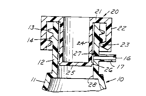
Fig. 4 is a sectional view similar to Fig. 3 showing the package in open
position.
Fig. 5 is a fragmentary sectional view showing the package in inverted
dispensing position.
Fig. 6 is a fragmentary sectional view of an apparatus for molding the
container.
Fig. 7 is a fragmentary sectional view of a child resistant form of the
package.
-2-

CA 02081060 1999-11-12
Fig. 8 is a sectional view taken along the line 8-8 in Fig. 7.
Description
Refernng to Figs. 1-5, the squeeze package embodying the invention
comprises a hollow container 10 of plastic material such as high density
polyethylene
including a body portion and a neck 12 that has a pair of annular beads 13,
14, the
upper bead 13 nearest the outlet of a opening 15 of the neck 12 having a
greater
diameter than the lower bead 14. A second opening 16 is defined by an integral
tubular portion that extends laterally, preferably at 90 ° to the axis
of the neck 12.
A closure 20 of plastic material such a polypropylene is provided that
includes
a top wall 21, a peripheral skirt 22 and a radially inwardly extending bead 23
that
normally is positioned below the lower bead 14. The closure 20 further
includes an
integral hollow plug portion 24 defining a cylinder having a closed bottom
wall 25.
The cylindrical portion 24 includes a flexible lower seal 26 and a vertically
spaced
flexible upper seal 27. Seals 26, 27 extend radially outwardly and preferably
have an
asymmetrical triangular cross.section that engages the inner surface 28 of the
neck 12.
When the closure 20 is on the container, the lower seal 26 isolates the
opening 16
from the contents of the container 11 and the upper seal 27 isolates the
interior of the
dispensing tube 17 from the upper portion of the closure 20.
In order to dispense the contents, the closure 20 is moved vertically upwardly
in the direction of the arrow shown in Fig. 4, to bring the bead 23 on the
closure into
position snapped between the lower bead 14 and the upper bead 13 of the neck
11.
The package is then inverted and squeezing of the wall body portion 11 of the
-3-

CA 02081060 1999-11-12
container will dispense the liquid in any desired direction by aiming the
tubular
portion 17 in the proper direction.
As shown in Fig. 6, the finish of the container is preferably formed by
injection molding plastic from an extruder die head 30 into a space defined by
a mold
core 31 and a split neck ring 32 wherein the neck ring sections 33 includes
annular
cavities 34, 35 for the beads 13, 14 and one of the neck ring sections 33 also
includes
a cavity forming the tube 17 with a secondary core pin 36 spaced to form the
cavity
for the tube 17. The body of the container can be formed thereafter by moving
the
neck ring 32 axially upwardly relative to the die head 30 and continuing to
extrude a
tubular plastic to form a parison which is thereafter enclosed in a blow mold
and blow
molded to form the container integrally with the neck, as is well known in the
art and
shown for example in United States Patents Nos. 2,710,987 and 3,029,471.
In the form shown in Figs. 7 and 8, a child resistant feature is added wherein
the closure 20a can not be moved axially without aligning proper portion of
the
closure and container. In this form, the lower bead 14a is provided with
diametrically
opposed notches 37 and the bead 24a on the closure comprises two lugs rather
than a
continuous bead which must be aligned with the notches in order to permit the
closure
to be moved axially upwardly. In all other respects, the package is the same.
It can thus be seen that there has been provided a squeeze pump system for
20 dispensing liquids in a desired direction which is materially lower in
cost; has lower
filling costs; and does not require any special fitment or nozzle.
-4-

Representative Drawing
A single figure which represents the drawing illustrating the invention.
Administrative Status

2024-08-01:As part of the Next Generation Patents (NGP) transition, the Canadian Patents Database (CPD) now contains a more detailed Event History, which replicates the Event Log of our new back-office solution.

Please note that "Inactive:" events refers to events no longer in use in our new back-office solution.

For a clearer understanding of the status of the application/patent presented on this page, the site Disclaimer , as well as the definitions for Patent , Event History , Maintenance Fee  and Payment History  should be consulted.

Event History

Description Date
Inactive: IPC from MCD 2006-03-11
Time Limit for Reversal Expired 2002-10-21
Letter Sent 2001-10-22
Grant by Issuance 2000-12-19
Inactive: Cover page published 2000-12-18
Inactive: Final fee received 2000-07-28
Pre-grant 2000-07-28
Notice of Allowance is Issued 2000-02-28
Letter Sent 2000-02-28
Notice of Allowance is Issued 2000-02-28
Inactive: Approved for allowance (AFA) 2000-02-08
Amendment Received - Voluntary Amendment 1999-12-09
Inactive: S.30(2) Rules - Examiner requisition 1999-11-22
Amendment Received - Voluntary Amendment 1999-11-12
Letter Sent 1999-10-05
Inactive: Status info is complete as of Log entry date 1999-10-05
Inactive: Application prosecuted on TS as of Log entry date 1999-10-05
Amendment Received - Voluntary Amendment 1999-10-01
All Requirements for Examination Determined Compliant 1999-09-20
Request for Examination Requirements Determined Compliant 1999-09-20
Application Published (Open to Public Inspection) 1993-04-22

Abandonment History

There is no abandonment history.

Maintenance Fee

The last payment was received on 2000-09-28

Note : If the full payment has not been received on or before the date indicated, a further fee may be required which may be one of the following

  • the reinstatement fee;
  • the late payment fee; or
  • additional fee to reverse deemed expiry.

Please refer to the CIPO Patent Fees web page to see all current fee amounts.

Fee History

Fee Type Anniversary Year Due Date Paid Date
MF (application, 5th anniv.) - standard 05 1997-10-21 1997-09-19
MF (application, 6th anniv.) - standard 06 1998-10-21 1998-09-22
MF (application, 7th anniv.) - standard 07 1999-10-21 1999-09-17
Request for examination - standard 1999-09-20
Final fee - standard 2000-07-28
MF (application, 8th anniv.) - standard 08 2000-10-23 2000-09-28
Owners on Record

Note: Records showing the ownership history in alphabetical order.

Current Owners on Record
OWENS-ILLINOIS PLASTIC PRODUCTS INC.
Past Owners on Record
THOMAS J. KRALL
Past Owners that do not appear in the "Owners on Record" listing will appear in other documentation within the application.
Documents

To view selected files, please enter reCAPTCHA code :


To view images, click a link in the Document Description column. To download the documents, select one or more checkboxes in the first column and then click the "Download Selected in PDF format (Zip Archive)" or the "Download Selected as Single PDF" button.

List of published and non-published patent-specific documents on the CPD .

If you have any difficulty accessing content, you can call the Client Service Centre at 1-866-997-1936 or send them an e-mail at CIPO Client Service Centre.


Document
Description 
Date
(yyyy-mm-dd) 
Number of pages   Size of Image (KB) 
Representative drawing 1999-03-18 1 8
Representative drawing 2000-11-16 1 11
Abstract 1993-11-20 1 22
Claims 1993-11-20 2 49
Cover Page 1993-11-20 1 13
Drawings 1993-11-20 3 76
Drawings 1999-10-01 3 75
Claims 1999-10-01 2 57
Cover Page 2000-11-16 1 40
Description 1993-11-20 6 145
Claims 1999-11-12 2 61
Abstract 1999-11-12 1 23
Description 1999-11-12 4 153
Reminder - Request for Examination 1999-06-22 1 118
Acknowledgement of Request for Examination 1999-10-05 1 193
Commissioner's Notice - Application Found Allowable 2000-02-28 1 166
Maintenance Fee Notice 2001-11-19 1 178
Correspondence 2000-07-28 1 27
Fees 1996-09-24 1 98
Fees 1995-09-28 1 91
Fees 1994-09-26 2 198