Language selection

Search

Patent 2081110 Summary

Third-party information liability

Some of the information on this Web page has been provided by external sources. The Government of Canada is not responsible for the accuracy, reliability or currency of the information supplied by external sources. Users wishing to rely upon this information should consult directly with the source of the information. Content provided by external sources is not subject to official languages, privacy and accessibility requirements.

Claims and Abstract availability

Any discrepancies in the text and image of the Claims and Abstract are due to differing posting times. Text of the Claims and Abstract are posted:

  • At the time the application is open to public inspection;
  • At the time of issue of the patent (grant).
(12) Patent: (11) CA 2081110
(54) English Title: DEVICE FOR PRODUCING GRANULES OR TABLETS FROM LIQUID MATERIALS
(54) French Title: DISPOSITIF DE FABRICATION DE GRANULES OU COMPRIMES A PARTIR D'UNE MATIERE PREMIERE LIQUIDE
Status: Deemed expired
Bibliographic Data
(51) International Patent Classification (IPC):
  • B01J 2/20 (2006.01)
(72) Inventors :
  • KAISER, HERBERT (Germany)
(73) Owners :
  • GEBR. KAISER MASCHINENFABRIK (Germany)
(71) Applicants :
(74) Agent: MACRAE & CO.
(74) Associate agent:
(45) Issued: 1996-11-05
(86) PCT Filing Date: 1991-04-22
(87) Open to Public Inspection: 1991-10-27
Examination requested: 1996-04-29
Availability of licence: N/A
(25) Language of filing: English

Patent Cooperation Treaty (PCT): Yes
(86) PCT Filing Number: PCT/EP1991/000771
(87) International Publication Number: WO1991/016151
(85) National Entry: 1992-10-21

(30) Application Priority Data:
Application No. Country/Territory Date
P 40 13 405.9 Germany 1990-04-26

Abstracts

English Abstract


In a device for producing granules or tablets from fluid materi-
als, the material is fed to the press-slot between a rotative hollow cylin-
der with an inner toothing and a press-cylinder with an outer toothing
that engages said inner toothing. Bores extend from the bottom of the
teeth of the inner toothing of the hollow cylinder up to its outer side,
the material is pressed through these bores when the hollow cylinder
engages the press-cylinder and is laid as tablets or granules on a cool-
ing surface. At least one part of the outer circumference of the hollow
cylinder remote from the cooling surface is surrounded by a heating
shell. Outside the heating shell (3), spaced apart from it, is arranged
another shell (5), in such a way that between the heating shell (3) and
the other shell (5), a waste gas shaft (4) is formed, in communication
with a suction nozzle (6) for the gases that emanate from the material.


Claims

Note: Claims are shown in the official language in which they were submitted.


- 7 -
THE EMBODIMENTS OF THE INVENTION IN WHICH AN EXCLUSIVE PROPERTY OR
PRIVILEGE IS CLAIMED ARE DEFINED AS FOLLOWS:
1. In an apparatus for producing granules or pastilles
from flowable material in which the material is supplied to a
pressing gap between a revolving hollow roll with internal toothing
and an externally toothed extrusion roll in engagement with said
internal toothing, said hollow roll rotating in a predetermined
direction, bores being provided which extend from the respective
teeth bottoms of the internal toothing of the hollow roll to the
outside of the hollow roll and through which the material is
extruded on engagement with the extrusion roll and deposited in the
form of pastilles or granules on a moving cooling surface having a
pastille discharge region, further wherein at least a portion of an
outer periphery of the hollow roll that is remote from the cooling
surface is surrounded by a heating jacket,
the improvement which comprises providing on an outer
side of said heating jacket and spaced therefrom a second
jacket means having an inner side and an outer side
arranged in such a manner that, between said heating
jacket and said second jacket means, a generally arcuate
waste gas well is formed comprising a first inlet opening
in an upstream region as seen in said predetermined
direction of rotation of said hollow roll and above said
pastille discharge region, and two end faces, said waste
gas well communicating with extraction connection means
for withdrawing any gases emerging from said material as
it cools.
2. Apparatus according to claim 1, further wherein said
heating jacket and said second jacket means are arranged at least
partially concentrically with respect to said hollow roll.


- 8 -
3. Apparatus according to claim 2, further wherein said
heating jacket and said second jacket means are arranged
substantially concentrically above a horizontal centre plane of said
hollow roll, said heating jacket and said second jacket means also
extending beneath said center plane in a direction towards said
cooling surface on said pastille discharge region thereof.
4. Apparatus according to claim 1, further wherein said
waste gas well comprises a second inlet opening at a downstream end
of said gas well as seen in said predetermined direction of rotation
of said hollow roll, said second inlet opening being partially or
completely sealed by an adjustable flap for controlling the inflow
of ambient air.
5. Apparatus according to claim 1, further wherein said
waste gas well is sealed at said end faces thereof.
6. Apparatus according to claim 1, further wherein said
second jacket means is provided on its outer side with an insulating
layer .
7. Apparatus according to claim 2, further wherein said
waste gas well comprises a second inlet opening at a downstream end
of said gas well as seen in said predetermined direction of rotation
of said hollow roll, said second inlet opening being partially or
completely sealed by an adjustable flap for controlling the inflow
of ambient air.
8. Apparatus according to claim 3, further wherein said
waste gas well comprises a second inlet opening at a downstream end
of said gas well as seen in said predetermined direction of rotation
of said hollow roll, said second inlet opening being partially or

- 9 -
completely sealed by an adjustable flap for controlling the inflow
of ambient air.
9. Apparatus according to claim 2, further wherein said
waste gas well is sealed at the end faces thereof.
10. Apparatus according to claim 3, further wherein said
waste gas well is sealed at the end faces thereof.
11. Apparatus according to claim 4, further wherein said
waste gas well is sealed at the end faces thereof.
12. Apparatus according to claim 2, further wherein said
second jacket means is provided on its outer side with an insulating
layer .
13. Apparatus according to claim 3, further wherein said
second jacket means is provided on its outer side with an insulating
layer.
14. Apparatus according to claim 4, further wherein said
second jacket means is provided on its outer side with an insulating
layer.
15. Apparatus according to claim 5, further wherein said
second jacket means is provided on its outer side with an insulating
layer.
16. Apparatus according to claim 8, further wherein said
waste gas well is sealed at the end faces thereof.

- 10 -
17. Apparatus according to claim 16, further wherein said
second jacket means is provided on its outer side with an insulating
layer.
18. Apparatus according to claim 11, further wherein said
second jacket means is provided on its outer side with an insulating
layer.
19. Apparatus according to claim 10, further wherein said
second jacket means is provided on its outer side with an insulating
layer.
20. Apparatus according to claim 8, further wherein said
second jacket means is provided on its outer side with an insulating
layer.
Description

Note: Descriptions are shown in the official language in which they were submitted.


208111~
BAur~KuuNLI OF THE INVENTION
The invention relates to i, uv -~ts in an apparatus for producing
granules or pastilles from flowable material.
Such an apparatus is known from DE-PS 3, 902, 957 . In this known
5 apparatus the flowable material is supplied to the pressing gap
between a rotating hollow rol l with internal toothing and an
externally toothed extrusion roll in engagement with said internal
toothing. From the respective teeth bottoms of the internal
toothing of the hollow roll bores extend to the outer side thereof
10 through which the material is extruded on engagement with the
extrusion roll and deposited in the form of pastilles or granules on
a cooling surface. The cooling surface is formed by a revolving
cooling belt which moves past the lower region of the hollow roll.
The portion of said hollow roll lying above a horizontal centre
15 plane of the hollow roll is covered by a heating jacket which
permits an influencing of the temperature of the hollow roll.
ûn emergence of the material from the bores of the hollow roll and
on deposition of the pastilles or granules on the cooling belt, in
the processing of many materials waste gases are formed which in
20 accordance with environmental protection regulations cannot be
released uncontrolled in the environment.
The invention is based on the problem of providing an apparatus of
the type mentioned at the beginning which with simple construction
permits reliable collection of the waste gases f orming in the
25 processing of the materials.
8UMMARY OF T~E INVENTION
In the improved apparatus of this invention, f lowable material is
supplied to the pressing gap between a revolving hollow roll with
l~d V.
. _

2~8111U

internal toothing and an externally toothed extrusion roll in
engagement with said internal toothing. Bores are provided which
extend from the respective teeth bottoms of the internal toothing of
the hollow roll to the outside thereof. On engagement with the
5 extrusion roll, the f lowable material is extruded through the bores
and deposited in the form of pastilles or granules on a cooling
surface. At least a portion of the outer periphery of the hollow
roll remote from the cooling surface is '`ULL~Ullded by a heating
j acket such that on the outer side of the heating j acket and spaced
10 therefrom is a further jacket arranged in such a manner as to create
a waste gas well therebetween . The waste ~as well is f ormed so as
to communicate with an extraction connection tube piece for
channelling the gases emerging from the deposited f lowable material
as it c0015.
15 Due to the fact that the waste gas well is also heated by the outer
side of the heating jacket, condensation of the collected gases in
this region is reliably avoided and the waste gases pass via the
waste gas well to an exhaust connection tube piece from whence the
waste gases can be supplied to solvent recovery and/or filter means.
20 To enable the extraction effect of the waste gas well to be
controlled, said waste gas well, preferably sealed at the end sides
of the hollow roll, can be sealed at its rear end, seen in the
direction of rotation and opposite the intake end for the waste
gases, by an adjustable flap which permits control of the ambient
25 air sucked in at this rear end.
I~d v5

8 2~glllO
Said flap is preferably articulately connected to the
further jacket so that in the partially opened state part
of the waste gases whic~l possibly emerge from material
adhering to the outer periphery of the hollow roll can also
be extracted.
The heating jacket and/or the further jacket preferably
extend over the region of the hollow roll lying above the
horizontal centre plane concentrically to said roll whilst
the intake end lying beneath said centre plane adjacent to
the region of the cooling surface on which the pastilles or
granules are deposited is directed directly onto said
cooling surface and possibly widened in order to improve
the induction effect for the waste gases. Said intake end
can extend substantially up to the vicinity of the cooling
surf ace .
An example of embodiment will be explained in detail
hereinaf ter with the aid of the drawings:
In the drawings:
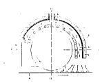
Fig. 1 shows a simplified schematic cross-sectional view
of one embodiment of the apparatus,
Fig. 2 is a sectional view along the line II-II of Fig.
1 shown broken away.
Fig. 1 shows in simplified form a cross-sectional view of
an embodiment of the apparatus, the basic apparatus
corresponding for example to that explained in detail in
DE-PS 3, 902, 957 .
Said apparatus comprises a hollow roll 1 which is provided
on its inner surface with an internal toothing which

'~' 4 208~
cooperates with the external toothing of an extrusion roll,
not illustrated, preferably arranged in the lower region Oe
the hollow roll. Material introduced into the nip or
pressing gap between the extrusion roll and the internal
toothing of the hollow roll 1 is extruded through bores
which extend from the teeth bottoms of the internal
toothing of the hollow roll 1 to the outer side thereof so
that said material is deposited in the form of pastilles or
granules 2 on a cooling surface, preferably a revolving
cooling belt 8.
Part of the periphery of the hollow roll 1 is provided for
controlling the temperature of said roll with a heating
jacket 3 which is arranged radially spaced from the hollow
roll 1 and which extends in most cases over the region of
the hollow roll lying above a horizontal centre plane 12
and concentrically to said roll
In the embodiment of the apparatus illustrated said heating
jacket 3 is surrounded in spaced relationship by a further
jacket 5 which preferably carries an insulating layer 9 on
its outer side. The further jacket 5 therefore forms
insulation for the outer side of the heating jacket 3 so
that the heat losses thereof are reduced. Between the
heating jacket 3 and said outer jacket 5 a waste gas well 4
is formed which communicates with an exhaust connection
tube pi ece 6 .
As apparent from Fig. 1, the intake end 11 of said waste
gas well 4, which lies a~ove the deposition region of the
pastilles on the cooling surface 8, is directed
substantially onto said cooling surface (beneath said
centre plane 12~; said intake end may if necessary be
widened in funnel form.

`~ 2~8~

Immediately after deposition of the material onto the
cooling surface 8 waste gases emerge from the pastilles or
granules 2 which should be sucked off as rapidly as
possible to prevent said waste gases getting into the
ambient air. Said waste gases however emerge from the
granules or pastilles 2 only over a limited distance on
further movement of the cooling belt ~ forming the cooling
surface so that the waste gas well 4 formed by the heating
jacket 3 and the further jacket 5 can effectively extract
said waste gases.
On the end of the exhaust well 4 opposite the intake end 11
an adjustable flap may be arranged which is preferably
articulately connected to the further jacket 5 so that on
partial opening of said ~lap 7 a gap is formed between said
flap and the heating jacl~et through which in addition to
the ambient air waste gases are also sucked in which escape
from the material which l~ossibly continues to adhere to the
outer surf ace of the hollow roll 1 on the movement thereof
away from the cooling belt 8 and if necessary is scraped
off said outer surface with the aid of a scraper plate 10.
The waste gas extracted ~ia the extraction connecting piece
6 from the waste gas well 4 can be supplied to a purifying
apparatus for the waste gas, for example a condensation or
filter means, 80 that the waste gases forming when the
material is deposited on the cooling belt 8 can be rendered
harmless in efficient manner.
In the manner already explained, the entrance of ambient
air into the extraction well and thus the extraction effect
at the intake end 11 of the waste gas well 4 can be
controlled by the flap 7. This makes it possible to
control in optimum manner also the efficiency of following

~ ~ 208111~

condensation and filter means behind the extraction
connecting piece 6.
The end faces of the waste gas well 4 formed by the heating
jacket 3 and the further jacket 5 may be either completely
or partially sealed to control an optimum extraction of the
waste gases forming during operation of the apparatus.
In simple manner, bv simple addition of a further jacket
the apparatus according to the invention permits effective
extraction of the waste gases forming in the product
deposition directly at their site of formation without
complicated extraction means being necessary.
By arranging the extraction well between the heating jacket
and the further ~acket and possibly by insulating the outer
side of the further jacket, condensation of said waste
gases in the waste gas well is reliably prevented.

Representative Drawing
A single figure which represents the drawing illustrating the invention.
Administrative Status

For a clearer understanding of the status of the application/patent presented on this page, the site Disclaimer , as well as the definitions for Patent , Administrative Status , Maintenance Fee  and Payment History  should be consulted.

Administrative Status

Title Date
Forecasted Issue Date 1996-11-05
(86) PCT Filing Date 1991-04-22
(87) PCT Publication Date 1991-10-27
(85) National Entry 1992-10-21
Examination Requested 1996-04-29
(45) Issued 1996-11-05
Deemed Expired 2001-04-23

Abandonment History

There is no abandonment history.

Payment History

Fee Type Anniversary Year Due Date Amount Paid Paid Date
Application Fee $0.00 1991-04-22
Maintenance Fee - Application - New Act 3 1994-04-22 $100.00 1992-04-14
Maintenance Fee - Application - New Act 2 1993-04-22 $100.00 1993-04-20
Registration of a document - section 124 $0.00 1993-05-11
Maintenance Fee - Application - New Act 4 1995-04-24 $100.00 1995-04-06
Maintenance Fee - Application - New Act 5 1996-04-22 $150.00 1996-03-28
Maintenance Fee - Patent - New Act 6 1997-04-22 $150.00 1997-03-12
Maintenance Fee - Patent - New Act 7 1998-04-22 $150.00 1998-02-18
Maintenance Fee - Patent - New Act 8 1999-04-22 $150.00 1999-02-04
Owners on Record

Note: Records showing the ownership history in alphabetical order.

Current Owners on Record
GEBR. KAISER MASCHINENFABRIK
Past Owners on Record
KAISER, HERBERT
Past Owners that do not appear in the "Owners on Record" listing will appear in other documentation within the application.
Documents

To view selected files, please enter reCAPTCHA code :


To view images, click a link in the Document Description column. To download the documents, select one or more checkboxes in the first column and then click the "Download Selected in PDF format (Zip Archive)" or the "Download Selected as Single PDF" button.

List of published and non-published patent-specific documents on the CPD .

If you have any difficulty accessing content, you can call the Client Service Centre at 1-866-997-1936 or send them an e-mail at CIPO Client Service Centre.


Document
Description 
Date
(yyyy-mm-dd) 
Number of pages   Size of Image (KB) 
Cover Page 1994-05-28 1 17
Abstract 1995-08-17 1 164
Claims 1994-05-28 3 60
Drawings 1994-05-28 2 31
Description 1994-05-28 7 231
Cover Page 1996-11-05 1 11
Abstract 1996-11-05 1 53
Description 1996-11-05 6 164
Drawings 1996-11-05 2 21
Claims 1996-11-05 4 93
Representative Drawing 1999-01-19 1 3
PCT Correspondence 1996-08-27 1 31
Office Letter 1996-05-17 1 42
Prosecution Correspondence 1996-04-29 1 38
Prosecution Correspondence 1996-04-29 2 56
International Preliminary Examination Report 1992-10-21 31 1,111
Fees 1997-03-12 1 62
Fees 1996-03-23 1 51
Fees 1995-04-06 1 31
Fees 1994-04-14 1 30
Fees 1993-04-20 1 34