Note: Descriptions are shown in the official language in which they were submitted.
2081358
DENTAL TOOL DRIVING APPARATUS
HAVING ROTATING AND ROTO-RECIPROCATING MOTIONS
5 Backg~o~n~
This invention relates to manually
deployable dental tool apparatus for driving a tool
implement. More particularly, the invention provides
10 such apparatus having both rotary and
roto-reciprocating motions.
Prior dental tools combining rotary and
axial motion include those disclosed in U.S. Patents
Nos. 4,175,324 (Arai); 4,629,426 (Levy); 4,341,519
15 tKuhn et al.); 4,289,849 (Lustiq et al.); and
4,544,356 (Gardella et al.). The prior devices of
these patents are primarily for use by a dentist or
other professional, and are not easily adaptable for
home dental hygiene use. Further, thè prior devices
20 that provide both rotary and axial motion by means of
eccentric cam rotation typically have a problem of
radial wobble. This radial wobble is inconvenient
for home users, and leads to imprecision during
delicate procedures such as root canal therapy. It
25 also can lead to e~cessive wear of internal parts.
Additional problems of prior dental tools that
provide combinéd rotary and axial motions include
costly manufacture and mechanical complexity. They
also have limited ability to discharge medication or
30 other fluid during use.
2081358
Accordingly, it is an object of this
invention to provide an improved manually deployable
dental tool for driving a tool implement selectively
with rotation and with rotary reciprocating axial
5 motion.
Another object is to provide a dental tool
of the above character having a stroke length that is
variable and that can easily be adjusted. Moreover,
it is an object to provide a dental tool of the above
10 character that can readily be arranged to dispense
fluid material to the dental site during operation.
A further object is to provide a dental tool
of the above charac~er having minimal radial wobble,
and otherwise operating with minimal vibration.
It is also an object to provide a dental
tool of the above character suitable for professional
office or home hygiene use.
Other objects of the invention will in part
be obvious and will in part appear hereinafter.
~ummary Of ~he Invention
A tool according to the invention drives a
tool implement with either of two motions. One is a
25 rotatinq motion about an output axis, and a second is
a roto-reciprocating motion of adjustable stroke
length. The stroke length can be adjusted readily
during operation.
The device has a hand-held housing that
30 mounts an output shaft element for rotation about an
output shaft and for reciprocation along the output
axis. The output shaft has opposed first and second
2081 3~8
ends, and the first end is arranged for removably and
replaceably mounting a tool implement. An input
element is mounted with the housing for driven
rotation about an input axis e~tending transversely
5 relative to the output axis. An intermediate element
couples the driving rotation of the input element to
rotate the output shaft. This coupling element ~an
be a gear engaged with gear teeth on the input
element and keyed to the output shaft element, so
10 that the output element is free for asial
reciprocation during rotation.
Because of the free asial movement between
the gear and the output shaft element, a cam
mechanism at the second end of the output shaft
15 element, combined with a spring, can impart rotary
axial reciprocation to the output element as it
rotates. The cam mechanism is adjustable to vary the
stroke length of the reciprocation.
More particularly, a tool according to the
20 invention features improvements in asial
reciprocating movement of the output shaft and
correspondingly the mounted tool implement. The
output shaft is drivingly engaged at the second end
with a cam. Rotational movement of the cam,
25 specifically a cam surface that estends
circumferentially about the output axis, relative to
a cam follower imparts axial movement to the output
shaft in a thrusting, outward direction to define the
reciprocal stroke length. With this combined
30 rotation and reciprocation, a point on the tool
output shaft travels through an eliptical path with
each full rotation of the shaft. Changing the stroke
~4~ 2~13~8
length of the reciprocation changes the length of one
axis of this eliptical trajectory.
A preferred cam follower is mounted with the
housing and has a ramp-shaped cam engaging surface
5 for selective adjustable engagement with the cam, to
adjust the length of the reciprocation stro~e.
A further feature of the invention is a
stroke adjusting element movably enqaged with the
housing. The stroke adjusting element, in one
10 embodiment, eccentrically rotates about the cam, to
enable the cam follower to selectively engage the
cam. The cam follower preferably is adjustably
movable between a first, fully engaged, position,
where it is fully engaged with the cam to impart
15 ma~imal axial movement to the output shaft; and a
second, disengaged, position distal to the first
position. When the cam follower is in the disengaged
position, the output shaft rotates without
reciprocation. At intermediate positions of the cam
20 follower, the output shaft rotates with reciprocation
of selected stroke length. The stroke adjusting
element preferably is manually accessible by the user
for continuous and gradual stroke length adjustment
during operation.
Another feature of the invention is a spring
mechanism resiliently engaged between the housing and
the output shaft. The spring mechanism imparts a
resilient restoring force in the direction opposite
the reciprocation force imposed by the cam. Thus,
30 the outward reciprocation stroke e~erted on the
output shaft by the cam and cam follower arrangement
is counteracted by an inward restoring force e~erted
~" ~5~ 2~8~3~
by the spring mechanism, to impart reciprocal axial
movement of the output shaft during rotation. In a
preferred embodiment, the spring mechanism is a wave
spring.
Further, a preferred embodiment of the
ramp-shaped cam engaging surface is downwardly angled
at forty-five degrees relative to the output asis.
The cam, which rotates about an asis, has a
cam surface that estends, in the radial direction,
10 traversely from that asis with different transverse
angles at different circumferential positions. The
cam surface thus has progressively different bevels,
relative to a plane perpendicular to the axis about
which it rotates, at progressively different
15 circumferential positions. In a simple embodiment,
the cam surface at one circumferential position
estends radially at essentially ninety degrees
transverse angle and hence has no, or minimal,
bevel. At the diametrically opposite circumferential
20 position, the cam surface has masimal bevel. ~he
bevel of the cam surface has a continuous progressive
transition between these two extreme bevels at
; circumferentially intermediate positions.
With this camming structure, the cam
25 mechanism imparts cyclic outward motion to the output
shaft, as that shaft and the cam rotate. Unlike
prior devices, a cam according to the invention is
concentrically drivingly engaged with the output
- shaft, and its surface is contoured to impart
30 progressive outward asial motion to the output shaft,
due to engagement with the cam follower.
: . ,
.
- ,
2081358
The cam interfits with and can be
mechanically fi~ed to the output shaft. A preferred
construction employs a central protrusion on the cam
seated in a central aperture in the output shaft.
5 The cam and output shaft have reciprocating spline
elements which interfit during assembly. The cam can
be mechanically fised to the output shaft, after
assembly of the coupling device with the output
shaft, by conventional means including an eposy
10 adhesive and heat or chemical bonding.
Other features of a tool according to the
invention include a housing-carried reservoir for
dispensing fluid material to the dental or other site
being worked. The housing and the output shaft can
15 have connecting passages for conveying fluid material
from the reservoir through the housing, and along the
passage in the output shaft, to be e~pelled either at
the first end of the output shaft or from the tool
implement attached thereto.
Although described with specific reference
to a dentist tool, features of the invention may have
application to other tools and to other cam
mechanisms.
25 Brief Description Of The Drawings
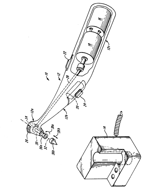
FIGURE 1 is a perspective view, partly
broken away, of a dental tool embodying the invention
and a battery-charging base for the dental tool;
-7- 20813~8
FIGURE 2 is a side elevation view, partly
cut away, of the power head portion of the dental
tool of FIGURE 1, with a tool implement mounted
thereon and with the cam follower disengaged to
5 produce only rotation of the tool;
FIGURE 3 is an exploded view of drive
elements of the power head of the dental tool of
FIGURE l;
FIGURES 4 and 5 are elevation views of the
lO dental tool power head, similar to FIGURE 2, with a
different tool implement and with the cam follower
engaged to produce roto-reciprocation of the tool,
and further showing different reciprocation positions
of the output shaft;
FIGURE 6 is a side elevation showing of the
liquid discharging conduit and passage for the dental
tool o FIGURE l;
FIGURES 7A, 7B, 7C, and 7D illustrate the
azial rotary reciprocation at different rotational
20 positions of the output shaft of the tool of FIGURE l;
FIGURE 8 is a diagrammatic showing of
different positions of the cam follower of the tool
of FIGURE 1 and corresponding different reciprocation
positions of the tool output shaft;
FIGURES 9A and 9B are fragmentary plan and
elevation views respectively of one stroke adjusting
mechanism for use with the tool of FIGURE l;
FIGURES lOA and lOB are fragmentary and side
elevation views of a second stroke adjusting
30 mechanism for the tool of FIGURE l;
FIGURES llA, llB, llC, and llD show
fragmentary plan and elevation views of a third
,
~'
' -- ..
-8- 2081358
stroke adjusting mechanism for use with the power
tool of FIGURE 1 in different rotational positions;
FIGURES 12A and 12B are fragmentary plan
views of a modification of the stroke adjusting
5 mechanism of FIGURES llA-llD in different rotational
positions;
FIGURES 13A and 13B are fragmentary
perspective and side elevation views respectively of
another stroke adjusting mechanism embodying features
10 of the invention; and
FIGURES 14A, 14B, and 14C are two plan views
and one elevation view respectively of a further
stroke adjusting mechanism for use with the power
tool of FIGURE 1 and embodying features of the
15 invention.
Description of Illustrated Embodiments
FIGURE 1 shows a dental tool 10 according to
20 the invention and having a manually deployable
housing 12. The tool can be seated in a power
charging base 14 for recharging a rechargeable
battery 16 carried in the housing. The housing has
an axial succession of three sections, namely a
25 forward power head or tool section 12a, a central
handle section 12b, and a back section 12c
illustrated as housing the rechargeable battery 16
that drives an electric motor 18. The housing back
section 12c also mounts a reservoir 20 of liquid,
30 such as medication for selective dispensing to the
dental site being treated with the tool. Also
mounted on the tool housing 12 are an on/off switch
22 and a fluid dispensing control switch 24.
9- 208~3~3
The tool housing is sized for an operator to
hold it with fingers encircled around it and with the
thumb or forefinger able to reach and operate the
on/off switch 22, the fluid dispensing switch 24, and
5 a stroke-adjusting switch 26 located on the forward
power head section 12a.
When the power switch 22 is turned on, the
battery-driven motor 18 rotates an input shaft 28
that is mounted within the housing 12. The driven
10 rotation of the input shaft 28 is coupled to an
output shaft 30 for rotating it about an output axis
32. In the illustrated tool, the output shaft
extends along an axis 32 extending transversely to
the asis of the shaft 28. A cam mechanism 34,
15 mounted in the tool power head section 12a and
coupled with the output shaft 30 and with the stroke
adjusting switch 26, imparts reciprocation to the
tool output ~haft 30 during this driven rotation.
The length of the reciprocation stroke is adjustable
20 by movement of the stroke switch 26.
As also shown in FIGURE 1, the tool output
shaft 30 can snap fit with any of several different
tool implements 36a and 36b. The illustrated tool
implement 36a is operated with rotation only, about
25 the tool output shaft 30, as designated with arrow
38a. The tool implement 36b is preferably employed
with combined rotation and a~ially reciprocation, as
designated with arrows 38b. Thus, one feature of the
tool 10 is to drive interchangeable elements with
30 exclusively rotary motion or with combined rotary and
reciprocating motion.
, .. . -.
o- 2~8~
With reference to FIGURES 2 and 3, the
illustrated tool housing 12 mounts the input shaft 28
for rotation about an axis 40 longitudinal with the
axial arrangement of the housing sections 12a, 12b,
5 and 12c. The illustrated input shaft 28 has, at its
forward output end in the housing power section 12a,
a bevel gear 42 that is drivingly engaged with a
mating bevel gear 44 on a gear element 46. The
output, gear end of the input shaft 28 is mounted
10 relative to the housing 12 for rotation about the
axis 40 by way of a bearing 48c A pair of bearings
50 and 52 seated with the housing rotatably mount the
gear element 46 for rotation about the output axis 32
and in fixed position axially along that axis for
15 maintaining engagement between the bevel gears 42 and
44.
The gear element 46 is seated on the output
shaft 30 and keyed with it, by internally projecting
keys on the gear that slideably seat in a~ial key
20 slots on the shaft 30, to rotate the output shaft in
response to driven rotation which the gear element 46
receives from the input shaft 28. The keyed
engagement of the gear element 46 with the output
shaft 30 allows the output shaft to reciprocate along
25 the output axis 32 independent of the gear element 46.
With further reference to FIGURES 2 and 3,
the illustrated output shaft 30 has, in succession
- along the a~is 32, a tool mounting end 30a, a bearing
shaft section 30b that slideably seats within a
30 bearing 54, a thrust ~ection 30c engaged with a
restoring spring 56, a key or spline section 30d
fitted within the gear element 46, and a spline end
, ".;.,, ,; ,,..,, ,. :
,.
-11- 2~8~3~8
section 30e illustrated as engaged with a thrust cam
60 that is part of the cam mechanism 34.
The output shaft 30 is thus mounted relative
to the housing 12, by way of the bearing 54 and
5 indirectly by way of the bearings 50 and 52 that
engage the gear element 46 with which the shaft is
engaged at the spline section 30d, for rotation about
the output axis 30 and for limited axial
reciprocation.
The output shaft thrust section 30c in the
illustrated embodiment has a cylindrical collar 62 of
enlarged radius for centering the restoring spring
56, and has a cylindrical flange 64 of larger radius
for compressive abutment against the restoring spring
15 56. The illustrated restoring spring 56 is a
compressive spring of annular configuration seated
around the shaft collar 62 and compressed between the
axial face of the shaft flange 64 and an axially
opposing annular shoulder 12d of the housing 12. The
20 spring 56, which preferably as illustrated is a
compound wave spring, e~erts a resilient
reciprocation-restoring thrust on the output shaft 30
directed inward along the output a~is 32, i.e.
directed away from the shaft tool end 30a and upward
25 in FIGURE 2.
The output shaft key section 30d mountingly
interfits within the gear element 46 for rotation
with the gear element about the axis 32 and for
movement along that axis independent of the gear
30 element. The output shaft spline section 30e has a
splined tubular inner passage into which a mounting
stem of the cam 60 telescopically fittingly
.. .. . ...
...... ..
,.,- ~ ..
-12- 20~13~8
assembles. The illustrated splined passage has a
square cross section and the cam stem has a
correspondingly square peg-like axially extending
shape for secure fit within the spline section.
The assemblage of the output shaft 30 and
gear element 46 and cam 60 is thus mounted in the
tool head section 12a with the spring 56 resiliently
urging the output shaft upward in FIGURE 1 and with
the shaft free for rotation, and free for axial
10 reciprocation against the urging of the spring 56.
With this construction, rotation of the input shaft
28 about the longitudinal axis 40 is transferred by
the bevel gear 42 to the mating bevel gear 44 of the
gear element 46, which in turn rotates the output
15 shaft 30.
FIGURE 2 shows a cam follower 62 of the cam
mechanism 34 adjustably positioned out of engagement
with the cam 60. In this position, the dental tool
10 output shat 30 rotates without any asial
20 reciprocation.
Upon movement of the stroke adjusting switch
26 to engage the cam follower 62 with the cam 60, the
tool output shaft 30 reciprocates along the output
axis during rotation, as now described with reference
25 to FIGURES 4, 5, and 7.
To obtain axial reciprocation of the output
shaft 30, the cam mechanism 34 deflects the output
shaft 30 to move the tool end 30a outward from the
housing 12, i.e. downward in FIGURES 4 and 5 with
30 each rotation of the shaft. The restoring spring
drives the shaft back into the housing, i.e. upward
in FIGURE 2 to complete the reciprocating stroke.
-13- 2~3~
The illustrated cam mechanism employs the cam 60
rotatable on the inner end of the shaft 30 and a cam
follower 62 that selectively interferes with the cam
60, forcing it to deflect along the output asis 32,
5 during each shaft rotation.
The illustrated cam 60, as shown in FIGURE 3
and in the series of views of FIGURE 7, is a
cylindrical member estending axially from the shaft
30, ar.d selectively domed with a cam surface 60a, on
10 the outer asial end. The cam surface engages the
illustrated cam follower 62 at a fised radial
position.
The cam surface 60a generally e~tends
transversely to the asis 32 about which it rotates
15 and with progressively different circumferential
positions thereon having progressively different
bevels relative to a plane perpendicular the asis
32. The cam surface thus faces asially, i.e. along
the axis 32. The bevels can have different contours,
20 including flat, as in the embodiment of FIGURE 7, and
rounded as in the embodiment of FIGURE 3 and with a
different radius at different circumferential
positions.
FIGURE 7A shows the cam 60 in a first
25 rotational position, designated 0, where the cam
surface 60a presents a masimal bevel to the cam
follower 62. At this rotational position of the cam
60, it is free of interfering engagement with the cam
follower, with the follower adjusted to the position
30 shown. Accordingly, there is no asial deflection of
the cam, and correspondingly of the output shaft 30.
The restoring spring 56 hence maintains the output
shaft 30 at a fully retracted position.
' -
,
-14- 2~8~3~8
The bevel of the cam surface 60a that
engages the cam follower 62 diminishes as the cam
rotates from the 0 position. FIGURE 7B shows that
at a 45rotational position of the cam, and
5 symmetrically at a 225 rotation of the cam, the cam
surface interferingly engages with the cam follower
62 to deflect the cam and correspondinqly the output
shaft by a stroke distance designated (sl).
The progressively changing bevel of the cam
10 surface 60a engaged with the cam follower 62
diminishes further as the cam rotates, so that at 90
and 270 rotations of the cam 60, as shown in FIGURE
7C, there is increased interference between the cam
60 with the cam follower to produce a larqer
15 reciprocating displacement, designated (s2).
FIGURE 7D shows that the 180 rotational
position of the cam 60, the cam surface presents a
minimal deflection to the cam follower 62 and there
accordingly is masimal reciprocating displacement,
20 designated (x3) of the cam and correspondingly of the
output shaft 30.
FIGURE 4 shows the tool 10 power head at the
minimal reciprocating displacement of the output
shaft 30, corresponding to the 0 rotational position
25 of the cam 60 as shown in FIGURE 7A. FIGURE 5 shows
the tool power head with maximal reciprocating
displacement of the output shaft, corresponding to
the 180 rotational position of the cam 60 as shown
in FIGURE 7D. The cam follower 62 has the same
30 position in each of FIGURES 4 and 5. FIGURE 5 shows
the increased compression of the restoring spring 56,
with increased displacement of the output shaft.
-15- 208~ 3~8
FIGURE 8 illustrates the adjustment of the
reciprocating stroke length due to adjustable
positioning of the cam follower 62. The cam follower
position as shown with solid lines presents minimal
5 interference with the cam 60, in the illustrated
instance no interference. Consequently, there is no
reciprocation of the output shaft, as indicated with
the solid line showing of the cam 60 and of the shaft
30 in FIGURE 8.
When the cam follower is adjustably
positioned for masimal interference, as shown in
FIGURE 8 with dash lines, it produces a maximal
output shaft deflection, as illustrated with the
dotted showing of the cam 60 and of the output
15 shaft. At intermediate positions of the cam
follower, the output shaft reciprocation has
intermediate stroke lengths.
The stro~e adjusting switch 26 of the
embodiment of the tool 10 shown in FIGURE 1 is
20 intregal with the cam follower 26, as FIGURES 9 and
10 show. A one-piece adjustment member 64 forms both
the switch 26 and the cam follower 62. More
particularly, the switch 26 is a protrusion on the
member 64 outward from the housing 12, through a slot
25 12e, for manual access by a user. The switch 26, and
a web 64a of the member 64 which carries the switch
and seats in the housing slot 12e, are elongated
along concentric circular paths, as shown in the plan
views of FIGURES 9A and lOA. The housing slot 12e
30 follows a circular path that matches the path of the
web 64a which the slot seats.
The cam follower 62 is a beveled,
concentrically inner extension of the adjustment
- -16-
208~3~8
member 64 and is radially located inward from the web
64a and is elongated along a non-circular path of
progressively decreasing radius from one end 62a to
the other end 62b.
With this construction, when the illustrated
adjustment member 64 is slideably moved to the
extreme counterclockwise position shown in FIGURES 9A
and 9B, the cam follower end 62a is positioned
adjacent the cam 60. This is the position of minimum
10 interference of the cam follower with the cam, as
FIGURE 9B shows, and accordingly produces zero or
selected minimal reciprocation of the output shaft 30
of the tool 10. Movement of the switch 26
counterclockwise from the position shown in FIGURE 9A
15 brings the cam follower increasingly into engagement
with the cam 60, and accordingly produces
progressively increasing reciprocation of the tool
output shaft. FIGURES lOA and lOB show the position
of ma~imal interference between the cam follower 62
20 and the cam 60, and corresponaingly of ma~imal
reciprocating stroke of the tool output shaft.
FIGURES llA through llD show a second
embodiment that employs a stroke adjusting switch 70
linked to a separate cam follower 72. The switch 70
25 is on an adjustment member 74 that is slideable along
a circular housing slot 12e, as in the embodiment of
FIGURES 9 and 10. The switch 70 and correspondingly
the housing slot 12e' of the embodiment of FIGURE 11
are illustrated as being on a top side of the
30 housing, in contrast to the lateral side location
shown in FIGURES 9 and 10. The adjustment member 74
slidingly engages the cam follower 72 with an arcuate
~ "
-17- 208~
rim 76a of diminishing radius between
circumferentially spaced ends 76a and 76b. The
illustrated adjustment member 74 also has a shelf 78
axially spaced from the rim 76 for seating the cam
5 follower 72 between the rim and the shelf, as FIGURES
llB and llD show.
With further reference to FIGU~ES llA
through llD, the cam follower 72 is a wedge-like
member arranged to move in a direction radial to the
10 asis 32, i.e. along the arrow 80. The cam follower
can be seated in a slot within the housing or have a
slot radial to the asis 32 that receives a housing
rail, or incorporate similar structures apparent to
those skilled in the art to confine the movement of
15 the cam follower to this sliding radial path. The
cam follower has a camming surface 72a at its
radially innermost end and that conforms to the
beveled camming surface on the cam 60. The radially
outer end of the cam follower 72 has a slot 72b that
20 sliaingly interfits with and receives the rim 76, for
radially positioning the cam follower.
FIGU2ES llA and llB show that when the
adjustment member 74 is in the estreme
counterclockwise position, the section of the
25 cam-positioning rim 76 engaged with the cam follower
72 has a large radial value. The cam follower 72 is
accordinqly positioned for minimal reciprocation of
the tool output shaft. Movement of the adjustment
member 74 clockwise from the position of FIGURES llA
30 and llB increasingly moves the cam follower 72
radially inward toward the asis 32 and into
increasing engagement with the cam 60, thereby
,
2~81358
producing increasing reciprocation of the tool output
shaft. FIGURES llC and llD show the adjustment
member 74 in its full clockwise rotational position,
where it positions the cam follower 72 for maximal
5 reciprocating stroke length.
FIGURES 12A and 12B show a modification of
the adjustment mechanifim of FIGURE 11 to provide a
detent-like action at the travel limits of the
adjustment member 74. The positioning rim 76' has
10 bulbous enlargements at each circumferential end 76a'
and 76b'.
Another embodiment of the stroke adjusting
mechanism for the tool 10, shown in FIGURES 13A and
13B, employs a wedge-like cam follower 82 slidably
15 seated within the housing between housing rails 84a
and 84b that flank a housing slot 86. A thumb screw
88 is threaded to the top of the cam follower,
through the housing slot 86. With this construction,
adjustment of the tool reciprocation stroke simply
20 involves loosening the thumb screw 88 and sliding it,
with the cam follower 82, along the housing slot 86
and again tightening the thumb screw to secure the
cam follower in the desired position radial to the
output azis 32.
A further embodiment of a tool according to
the invention has, as shown in FIGURE 14, a cam 60 as
previously described on the end of the tool shaft 30
and engaged by a rotary adjustable cam follower 92 to
select the stroke length of output shaft
30 reciprocation. More particularly, the tool of FIGURE
14 has a rotary stroke adjusting switch 94 accessible
on the top side of the tool housing. The rotary
2081358
switch 94 is on a stem 96 that passes through a
housing opening to mount a rotary cam follower 92
within the housing. A rotary sealing disk 98,
illustrated as carrying an O-ring 100 that sealingly
5 slidably engages the housing wall, is also mounted on
the stem g6 to seal the housing opening from dirt,
spillage and other debris. The stem 96, which
e~tends parallel to the output shaft axis 32, e~tends
a~ially within the housing beyond the cam follower 92
10 to seat in a support socket 102, t.ypically recessing
an inner projec~ion of the housing.
The illustrated rotary cam follower 92 has a
circular trusto-conical shape to engage the cam 60
with a beveled camming surface. The cam follower is
15 mounted off-center to the stem 96, and hence rotates
about an off-center axis.
With further reference to FIGURES 14A, B,
and C, the rotary adjustment switch 94 and cam
follower 92 are arranged to rotate as a unit with the
20 stem 96, as well as with the sealing disk 98. Rotary
adjustment of the switch 94 rotates the cam follower
92 from the position shown in FIGURE 14B, where it
has minimal interference with the cam 60,
progressively through 180~ to the position shown in
25 FIGURE 14A, where the cam follower has ma~imal
interference with the shaft carried cam 60.
A further feature of the tool 10 is that it
can dispense liquid, such as medication or a dental
cleaning preparation, to the dental site being
30 treated. The tool housing 12 carries a reservoir 20
and fluid dispensing switch 24, as shown in FIGURE
1. A tube 104 feeds liquid from the reservoir 20 to
, ~ ~
-20- 20813~8
the forward power head section of the housing and, as
shown in FIGURES 2 and 6, through a central bore 106
in the cam 60 and in output shaft 30. The
illustrated tube 104 estends substantially the full
5 length of the output shaft to discharge liquid
directly into whatever tool implement its fitted on
the output shaft. The tool implement 36a, shown in
FIGURES 1 and 2, has a central passage 36c for
receiving liquid discharged from the tube 104, and
10 delivering it to the dental site. The passage of the
tool implement 36a preferably ends with an orifice
36d that is normally closed and that opens in
response to the implement being pressed onto a
surface. Thus, the operator of the tool 10 fitted
15 with the implement 36a can control the discharge of
liquid both with the switch 24 on the tool housing
and, further, by controlling the pressure with which
the tool implement is pushed onto the dental site
being treated.
FIGURES 4 and 5 show that the tool imple~ent
36b also has a central passage for receiving liquid
from the tube 104 and that feeds into radial
discharge ducts from which the liquid is dispensed to
the dental site being treated.
A tool having the features described
hereinabove thus rotates an output shaft and provides
asial reciprocation of the shaft, with adjustable
reciprocation stroke with a mechanism that operates
with minimal vibration and without eccentric
30 wobble-producing elements. The drive mechanism of
; the tool has a high degree of axial symmetry that
enhances smooth operation and enhances the ready
.
,.
-21- 2~813~8
delivery of liquid medication and like substances to
the site being treated. The tool can employ a number
of different adjustment mechanisms for controlling
the stroke of the a~ial reciprocation.
It will thus be seen that the objects set
forth above, among those made apparent from the
preceding description, are efficiently attained.
Since certain changes may be made in the above
constructions without departing from the scope of the
10 invention, it is intended that all matter contained
in the above description or shown in the accompanying
drawings be interpreted as illustrative and not in a
limiting sense. It is also to be understood that the
following claims are to cover all of the generic and
15 specific features of the invention herein described
and all statements of the scope of the invention
which, as a matter of language, might be said to fall
therebetween.
Having described the invention, what iB
20 claimed as new and secured by Letters ~atent is:
.