Note: Descriptions are shown in the official language in which they were submitted.
5 9
SWIRL RING A~D FLOW CONTROL PROCESS
FOR A PLASMA ARC TORCH
Reference to Related Applications
This application is a continuation-in-part of
U.S. application Serial No. 07J513,780 filed on Aprll
24, 1990.
Backqround Of The Invention
This invention relates in general to plasma
ar~ cutting and welding processes and apparatus. More
specifically, it relates to a process and apparatus
for reducing electrode wear, particularly in high
power torches.
Plasma arc torches have a wide variety of
applications such as the cutting of thick plates of
steel and the cutting of comparatively thin sheets of
galvanized metal commonly used in heating, ventilating
and air conditioning (HVAC) systems. The basic
components of a plasma arc torch include a torch body,
an electrode (cathode) mounted within the body, a
nozzle (anode) with a central exit orifice, a flow of
an ionizable gas, electrical connections, passages for
cooling, and arc control fluids, and a power supply
that produces a ~ilot arc in the ga~, typically
between the electrode and the nozæle, and then a
plasma arc, a conductive flow of the ionized gas from
2 ~ 9
the electrode to a workpiece. The gas can be
non-reacti~e, e.g. nitrogen, or reactive, e.g. oxygen
or air.
Various plasma arc torches of this general
type are described in U.S. Patent Nos. 3,641,304 to
Couch and Dean, 3,833,787 to Couch, 4,203,022 to Couch
and Bailey, 4,421,970 to Couch, 4,791,268 to Sanders
and Couch, 4,816,637 ~o Sanders and Couch, and
4,861,962 to Sanders and Couch, all commonly assigned
with the present application. Plasma arc torches and
related products are sold in a variety of models by
Hypertherm, Inc. of Hanover, New Hampshire. The MAX
10~ brand torch of H~pertherm is typical of the medium
power torches (lO0 ampere output) using air as the
working gas and useul for both plate fabrication and
HVAC applications. The HT 400 brand torch is typical
of the high power torches (26~ amperes) often using
oxygen as the work;ng gas. High power torches are
t~pically water cooled and used to pierce and ~ut
thick metal sheets, e.g. 1 inch thick mild steel plate.
In all plasma arc torches, a common and
heretofore unsolved problem has been a substantial
wear of the electrode, particularly whe~ th~ electrode
is used with reactive gases such as oxygen or air.
(Improved wear, other conditions being the s~me, i5
observed when using non-r~acti~e gases such as
nitrogen ~r argon as the plasma ga~, but the
performance using pure oxygen is superior at least
w~en used to cut certain materials such as mild
steel. Similarly, air is superior to pure oxygen with
respect to wear, but there is again a performance
trade off.) As an example of this wear problem, the
208~5~
standard electrode for the MAX 100 brand torch of .
Hypertherm, Inc. shows wear as a generally concave pit
on the lower end of the electrode, or more precisely,
on an emitting element o hafnium mounted on the
electrode. On average a wear dep~h of about 0.025
inch is observed in such a Hypertherm brand electrode
after 120 cut cycles operating with oxygen or air.
The wear results of commercially available units of
others, as measured by Hypertherm, Inc., are typically
worse. For the MAX 100 brand ~orch, when the wear
produces a pit depth of 0.060 inch or more,
Hypertherm, Inc. recommends that the electrode b~
replaced. In ordinary use, the electrode of a plasma
arc cutting torch operating with reactive gases
~ypically reguires replacement after 0.5 to 2 hours of
use depending strongly on the number of on-off
cycles. Wear considerations are significant not only
because they necessitate the repeated replacement of a
component, but also because they limi~ the maximum
power that can be applied to a given torch. With
particular reference to the present invention, it has
proven especially difficult to control electrode wear
in high current torches, e.g. the water cooled torches
sol~ by Hypertherm, Inc. under the trade designation
HT ~00 and PAC 500, respectively.
In plasma arc cutting, it is also impor~ant
to note that the ~uality o the cut i~ highly
dependent on the flow pattern of the gas in a plasma
chamber, defined at least in part as the region
between the electrode and the nozzle. In particular,
a swirling flow produced by injecting the gas
tangentially into the plasma chamber has been found to
. . .
2~8~9
be essential to produce a high quality cut. A
swirling gas flow pattern is also important in
stabilizing the plasma arc so ~hat it exits the ~orch
to attach to and cut the workpiece, but does not
contact the torch nozzle itself. The nozzle is the
principal component that is damaged by the arc when
the arc is not well controlled. Heretofore ~he
swirling gas ~low is o~ten produced mainly by a swirl
ring Shat has angled holes formed in the ring that
feed a swirling gas flow to the plasma chamber. The
aforementioned U.S. Patent No. 4,861,926, also
describes a swirling secondary cooling gas flow
passing between the nozzle and a surrounding shield
member to assist in the arc stablli2ation.
Another design consideration is the very high
temperatures of the plasma, e.g. greater than
10,000C. These temperatures introduce corresponding
changes in the gas properties such as its density and
viscosity. These considerations are significant on
start up and cut-off. On start up the arc rapidly
heats the gas which significantly decreases the gas
density exiting the nozzle orifice. This present~ ~he
situation where the gas flow is choked in the nozzle
orifice region. This choking is, in general,
advantageous during cutting since it restricts the
flow of gas rom plasma chamber to atmosphere and
thereby maintains a~ elevated gas pressure level in
the plasma chamber that constricts the arc. This
leads to an improved cut. A typical gas pressure in
~he plasma chamber to achieve these beneficial effects
in a medium to high power torch is about 40 psig. On
cut-off of the arc current, the situation reverses and
kosl~s
there is a tendency for the gas in the plasma chamber
~o cool and blow out of the chamber very suddenly.
It is common industry practic~ to use hanium
or 2irconium as the ca~hodic emitter inser~ in the
electrode. Hafnium, a~ o~ today, is the be~t choice
for the cathodic emitting el~ment when cutting with a
reac~ive gas plasma. It exhibi~s the lea~t wear of
all other materials tried ~or this application~ but is
more costly than other materials. These electrodes
never~heless reguire frequent replacement. Lower wear
has been as~ociated with lower current level~, but at
some po;nt the reduction in performance associated
with a reduced operating current becomes too great.
Cooling the electrode has also been used to increase
electrode life, whether by way o~ a gas ~low or water
flow placed in good thermal communication with ~he
electrode. Howe~er, water cooling is expe~sive,
cumbersome and is not desirable for low current units,
e.g. those rated below 100 amperes. Air cooling is
less efficient and limits the maximum operating
current of the torch, even one carrying a
comparatively low current. Therefore, to date, the
only practical solution to the electrode wear problem
has been to replace the entire electrode again and
again, despite the clear economic disadva~tage~ o
this approach.
It is therefore a principal object of the
present i~vention to reduce the wear on the electrode
of a plasma arc torch significantly and ther~by extend
it~ life.
Ano~her ~rincipal object of thi~ invention i~
to reduce electrode wear ~nd thereby allow operation
~81~
at higher current levels than are presently easible,
even when operating with reactive gases.
Still another pri~cipal object of thi~
invention is to provide a swirl ring which in addition
to producing a swirling output of ~he gas also:
controls the gas flow to the plasma chamber and the
distribution o the gas i~ the plasma chamber.
Another object of the invention i~ to achieve
a better cut guality than has heretofore been possible
by allowing a greater level of swirl.
Another o~ject of the invention is to provide
the foregoing advantages while using standard
electrode and nozzle constructions and without any
significant increase in the incidenc~ of damage to
torch parts such as nozzle gouging.
Yet another object of the i~vention i~ to
provide the foregoing advantages for existing plasma
arc torch systems using only comparatively ~imple and
inexpensive modi~ication~.
A still urther object is to provide the
foregoing advantages at a favorable cost vf
manufacture and operation.
Summary of the Invention
-
A plasma arc cutting torch, particularly o~e
using a reactive ga~ and employed in cutting me~allic
materials, has a torch body that mounts an ~l~ctrode
and a nozzle in a spaced relationship to define a
plasma charnber therebetween. An ionizable ga~ is fed
by an inlet system which can consist of tubes,
passages and/or cham'Qers to and through l:he torch body
.. . ... . . . . .
`
r 2 (~ 81 A~ ~; 9
--7--
to a swirl ring mounted in the torch hody. The swirl
ring feeds the gas to the plasma chamber in a swirling
flow pattern where it is ionized and exits the ~orch
via a central exit orifice formed in the nozzle. The
torch also includes standard electrical connections to
a power supply and an electrical controller ~o
initiate a pilst arc în the yas in the ch~mber and
th~n transfer ~he arc to a workpiece for cutting or
other operations.
The swirl ring of th~ present invention is an
annular member mounted in the torch body adjacent the
electrode, the nozzle and the plasma chamber. It is
typically secured between the torch body and the
nozzle. The swirl ring includes a pre-chamber,
preferably an annular recess extending around the
outer surface of the swirl ring. A set of shoke
passages are formed in an upstream face of the swirl
ring to conduct gas from the gas inlet system in the
torch body to the pre-chamber. The number,
distribution and size of these choke passages restrict
the gas flow and thereby introduce a gas pressure drop
on the feed line immedia~ely before the plasma
chamber. The plasma gas exits the pre-chamber to the
plasma chamber via a set of angled holes found in the
downstream face o the ~wirl ring. In the preferred
form the swirl ring also include~ a set of radial
outle~ holes leading ~rom the pre-chamber to the
plasma chamber.
The swirl ring includes annular recess~s for
o-rings that seal the ~wirl ring to the torch body at
its upstream face, to the nozzle at its downstream
face, and to a current ring or other surrounding torch
2~4~9
component at its outer lateral face. In the preferred
form the pressure drop along the gas inle~ hole~ to
the swirl ring is about 32 psi when the plasma reaches
steady state and the gas pressure in the plasma
chamber is about 40 psi.
This gas control swirl ring is,particularly
useful when the electrode wear is further controlled
by altering the mass flow rate of the gas, and/or its
flow pattern, immediately before and immediately aftèr
the step of cutting off of the current to the torch.
The mass flow rate is reduced by either c~osing off or
reducing the gas flow to the plasma chamber~ This
mass flow rate reduction is timed to o~cur within a
few hundred milliseconds before the curr~n~ cut off,
and preferably continue aft~r cut off~ The process
step of cutting the arc current can be accomplished by
a sudden step function of time or a gradual ramp
function of time~ The reduction in the gas flow may
be coupled with a venting of the plasma chamber to
atmosphere to facilitate a more rapid change in the
gas flow pattern in the plasma chamber.
The present swirl ring with gas control
invention can also be viewed as a process
characteri~ed principally by the creation of a
pressure drop i~ the gas feed line to the plasma
chamber at a point immediately be~ore the plasma
chamber. This pressure drop i~ sufficiently low that
at steady ~tate operation the arc is stable and well
controlled. The pressur8 drop is also sufficien~ly
~igh that when the gas flow to th~ torch is cut off~
the gas flow through the plasma chamber i~ al~o cut
off rapidly. This limits a sudden and large outrush
.
2~81~9
g
of gas from the plasma chamber as the arc extinguishes
and the plasma gas cools. The process includes
providing a small localized source of gas immediately
adjacent the plasma chamber ~o that there is
sufficient gas available to the plasma chamber to
maintain control over the arc after the gas flow is
cut off, but before the arc is fully extinguished and
could o~h0rwise damage the torch. These proce~s
features can al~o be achieved by placing the
aforementioned flow restrictions and pre-chamber in a
torch component or components other than th~ swirl
ring, such as a portion of the torch body adjacent the
plasma chamber.
These and other features and objects of this
invention will be more fully understood from the
detailed description which should be read in light of
the accompanying drawings.
Brief Description Of The Drawinqs
Fig. lA is a simplified schematic view o a
prior art typical plasma arc torch connected to ~ gas
- flow control that controls the ga~ flow to the torch
to reduce electrode wear;
Fig. lB is a view in ~orizontal sectio~ alo~g
the li~e lB-lB in Fig. lA;
Fig~ lC is a ~implified schematic view of a
plasma arc cut~ing fiy~tem using the tor~h shown in
Figs. lA and lB;
Fig. ~D is a six graph timing diagram of the
gas flow alteration in relation to the cut-off arc
- current that has been found to extend electrode life;
14~
Figs. 2A, 2B and 2C correspond to Figs. lA,
lB and lC and show an alternative arrangement for
electrode wear reduction utilizing a valved vent in
combination with a valved gas feed;
Figs. 3A, 3B, 3C, and 3D correspond to Fig~.
2A - 2C, Figs. 3B and 3C corresponding to Fig. 2B, and
~how an alternative arrangement utilizing axial and
radlal inlet hole sets in a swixl ring to establish
either swirled or axial gas flow pattern~ in the
plasma chamb~r;
Fig. 4 is a simplified schematic view
c~rrespondin~ to Fig. lC showing flow control
mechanisms in the gas supply line to provide a preflow
and.xamp up of the flow on ~tart up as well as a ramp
down on cut of f;
Fig. 5 i~ a five graph timing diagram of the
gas flow alteration on start-up;
Fig. 6 i~ a simplified view in vertical
section of a swirl ring with a gas control function
according to the present invention mounted in a plasma
arc torch of the general type ~hown in Figs. lA, lC,
2A, 2C, 3A, 3D and 4, with ~he upper portions of the
torch body broken away and other components, such as a
retaining cap, omit'ted;
Fig. 7 is a bottom pla~ view of the swirl
ring only sho~m in Fig. 6 taken along the line 7-7; and
Fig, 8 is a graph plotting the gas pressure
i~ the plasma chamber of the torch show~ in Fig. 6 as
a function of ~ime during one cycle of operation and
also plotting the arc current carried by the plasma
o~er the same cycle of operation.
~D 2 ~
De~ailed Description Of_The Preferred Embodiments
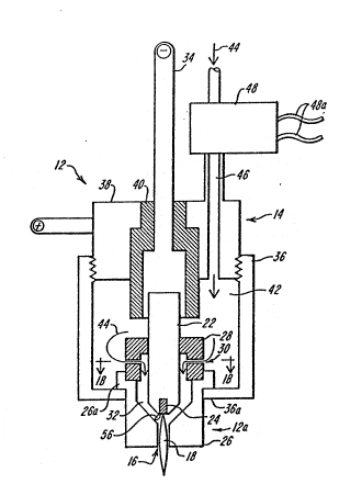
Figs. ~A and lB ~how in simplified schematic
form a typioal pla~ma arc cutting torch 12 such as any
of a varie~y of models of ~orches sold by Hypertherm,
Inc. The i~mediately follpwing description is
therefore intended ~o illus~rate the basic principles
and elements common to pla~ma arc cutting torches of
this type, bu~ not to describe construc~ion details o~
any particular torch model. The torch ha~ a body
indicate~ generally at 14 which typically is
cylindrical with an exit orifice 16 at one end, th~
lower end 12a as shown, through which a plasma arc 18,
an io~ized gas jet, passes and attaches to a metal
workpiece 20 which is being cut. The gas can be
non-reactive, such as nitrogen or a noble gas, but it
can also be reactive, such as oxygen or air. A
significant advantage of the swirl xing a~d associated
gas control process of the present invention is that
the torch can operate with a reactive gas and
nevertheles~ have dramatic impro~ement in electrode
wear even when operating at high power levels.
The torch body 14 supports a cathode 22,
commonly referred to as an electrode, which is
typically made of copper and has a generally
cylindrical configuration. An emitting element 24 i~
press fitted in~o the lower end ~ace of the electrode
22. ~he electrode and the emitting element are
sentered within the torch bod~ and aligned with the
exi~ orifice 16. When using a reactiv~ gas, the
insert i8 typically formed of hafnium or zirconium.
The body 14 al~o mounts a nozzle 26 with a central
.. . . . .. ..
208~9
-12-
nozzle oriice that defines the torch QXit orifiCQ
16. The nozzle is ~paced rom the electrode. A swirl
ring 28 of conventional construction and having a ~et
o radially off~et gas di~tribution hol~s 30 is
replaceably mounted in the torch body. It is
positioned to fesd a flow of the pla~ma gas ~rom the
holes 30 to a pla~ma arc chamber 32 defin2d, a~ ~hown,
by the electrode, the nozzle and the swirl ring.
With this prior art conventional swirl ring
the offset of the holes, best seen in Fig. lB,
introduces a tangential ~elocity component to the gas
flow through the chamber 32 causing it to ~wirl. With
the electrode wear reduction advantag~s described
herein, the level of ~wirl introduced by these holes
can be greater than ha~ heretoore practi~able
resulting in a better cut quality than has heretofore
been attainable. The swirl ring i~ shown in a tight
fitting, gas sealed relationship to ~he elec~rode. It
will be understood, however, that the swirl ring is
often mounted in a support member and does not itself
seal to the electrode. More generally, the particular
construction detail~ o the torch body ~nd
arrangements for mounting these elements directing gas
and cooling fluid flows and providing ele~trical
connections can and do take a wide variety o~ forms.
A ~egative power lead 34 surrounds the upper
end of the electrode 22 to mak~ a good electrical
connection. A r~taining cap 36 threads onto a curren~
ring 38 that forms the upper end of the torch body
}4. An in~ulatsr sleeve 40 separates and electrically
isolates the curr~nt ring 38 from the negatiYe pow~r
le~d 34. The retaining cap has a lower lip 36a which
208~9
engages a flange 26a on th~ nozzle in an abutting
relationship. The retaining cap when tightened onto
the ring 38 captures and replaceably secures the
nozzle against the swirl ring. In ~n alternative
construction not sho~, it can also capture and ~ecure
the swirl ring between the ~ozzle and another internal
support structure within the torch body. In the
coniguration ~hown, the retaining cap 36 also, in
par~, defines a gas plenum chamber 42 tha~ acts as a
local supply to the swirl ring 28 and ~he plasma
chamber 32. A flow 44 of plasma gas passes ~hrough an
inlet tube 46 which penetrates the current ring 3~ to
~eed the gas to ~he plenum chamber 42. A solenoid
valve 48 such as Model No. AFP33183 manu~actured by
Automatic Switch Company is secured in the inlet tube,
preferably at a point closely spaced from the torch
body. Control signals to the valve over lines 48a,48a
open and close the valve to regulate the flow rate of
the gas to the torch. In a pilot arc mode of
operation, where a pilot arc is drawn between the
electrode and the nozzle thrvugh the gas in the plasma
chamber, the nozzle acts as an anode and the aap 3~ ¦
and current ring 38 form a pilot arc current return
circui~.
In operation, plasma gas 44 flows through the
solenoid ~alve 48 and the i~let tube 46 i~to the
plenum chamber 42. From there, it ~lows through the
ga~ distribution holes 30 in the swirl ring 8 into
the plasma arc chamber 32 and finally out of the torch
through the nozzle orifice 16. When the torch i~
operating in the nontransferred pilo$ arc mode, a
power supply 50 prov;des current to the torch at an
~ ~ v ~ 9
-14-
appropriats voltage to i~itiate the pilot arc and then
maintain it. The power supply can be any conventional
regulated D.C. supply and includes a p.c. board or the
like which controls the operation of the power supply
and other components o~ the torch system such as ~low
control valves.
With reference to the complete plasma arc
cutting torch system 52 depicted in Fig. lc, ~he
complete current path in the nontransferred pilot arc
mode is from the negative power supply terminal 50a,
through lead 5~, ~he negative power lead 34, electrode
~2, a pilot arc pl~sma 56 (Fig. lA), the nozzle 26,
the retaining cap 36, the current ring 38, a pilo~ arc
return lead 58, a closed pilot arc ~witch 60, and a
power supply positive terminal 50b. When the torch 12
is lowered toward the workpiece 20, the arc transfers
~o the workpiece as the ionized plasma jet 18. This
allows ~ome current to flow from the workpiece through
a ground lead 62 back to the power supply positive
terminal 50b. When ~his transferred current path is
established, the pilot arc switch opens ~nd the torch
is cutting the workpiece. In this transerred or
cut~ing mode, the current path is rom the power
supply negative terminal 50a, the lead 54, negative
pow~r lead 34, electrode 22, the plasma ar~ or ~et 18,
the wor~piece 20, the ground lead 62 and the power
~upply positive ~erminal 50b.
An operator sets a desired gas flow or
pressure assoclat~d with full power operation in a
transferred arc mode prior to initiating the pilot arc
at a control ~onsole 64 which is removed from the
torch itself. The console includes ga~ flow
.
20814~9
--15
regulators, gas valving, and pressure gauges. The
flow and pressure values ~et by ~he operator at the
console correspond in a known way to the actual gas
flow-and pressure in the plasma chamber 32 prior to
the pilot ar~. Starting the pilot arc heats ~he gas
causing a~ increase in the gas ~emperature within the
chamber and a decrease in the flow, in a manner well
known in the art. A ~pical gas pressure in the
chamber 32 during the pilot arc is 20 to 40 psi. For
high power torches which are the particular focus of
the present invention, the gas pressures are usually
at or near 40 psi. The pilot arc is started by a
high-frequency spark or other means, such as a contact
starting technigue, all of which are well known in the
art. During start up ~he plasma gas 44 flows through
th~ tube 46, solenoid valve 48, plenum chamber 42,
swirl holes 30, the plasma chamber 32 and out the exit
orifice 16. As noted above, the swirling flow
established by the holes 30 is very important in
ob~aining a good quality cut and in stabilizing the
arc within the nozzle exit orifice 16 -- to prevent
the arc from impinging on the noæzle and gouging it.
As will be di~cussed in detail below, the operational
life of the electrode can be increased further by
utilizing a novel start up procedure and the apparatus
illu~trated in Figs. 4 and 5 and the novel swirl ring
and asæociated gas flow control functions described
with reference to Figs. 6-8.
Also as noted above, the torch b~gins autting
wh~n it is brought close to the workpiece so that the
arc transfers to the workpiece and the controller
opens switch 60. After transfer, in normal operation
2 ~ 9
-16-
the controller increases the current level to a
predetermined value for cutting. This increase in
current also resul~s in an increase in the heating of
the plasma ga~, a further increase in the gas pressure
in t~e plasma chamber, and a further decrea~e in the
gas flow out of the nozzle exit orifice~ The maximum
recommended current levels Yary greatly among
different torches and applica~ions, with currents in
the range of about 20 to 200 amperes D.C. being
characterized as low currents and those 200 and above
being high currents. A typical current level for a
water cooled cut~ing torch used ~o cut plate steel is
260 amperes.
A discovery of applicants is ~hat a
significant loss of material (wear) of the Plectrode
during its operation occurs not during the actual
cutting, but rather when the current to the arc is
shut off. While the mechanisms for this wear are not
fully understood, there is evidence that the electrode
becomes molten, at least in part, during operation and
that on ~ut off of the electrical power wear i5
rela~ed ~o a complicated interaction between the
molten surface(s~ of the electrode and the flow and
pressure of the plasma gas through the plasma ~hamber.
The ~wirl ring and associa~ed gas flow
control process of the present invention builds o~
applica~' discovery that a control of the plasma ga~
~low to the pla~ma chamber in conjunction with a
controlled electrical shut off to reduce electrode
wear substa~tially. In its simplest form, thi~ wear
reduction involves a total shut off of the pla~ma gas
flow to the chamber 30 just before (1) a total, step
.. . . . . . . . . . .. .. . . .
2081~g
function shut off of the arc current or (2) at the
same time ~he arc current starts a gradual shut of~,
but also just ~efore a total shut of of ~he arc
cuxrent. This efect is achieved by closing.the
solenoid valve 48 just pxior to the total 6hutting of
proc~ss of the arc curr~n~. The preferred process for
~hutt;ng off the curren~ is a controlled linear
decreasing ramp which follows the decreasing mass
flow. The ~iming of these shut offs is, however,
critical. If the gas flow is allowed to decrease
rapidly, there is a significant diminution of the
swirling plasma flow that stabili~es the arc.
Therefore the arc can and will attack and damage, or
even destroy, the nozzle in a very short time. ~n the
other hand, if the shut-offs are too close in time,
the gas flow and pressure in the chamber 30, which
decay in a generally exponential manner with the ~alve
~8 shut, e~hibit little ahange and wear occurs to
about the same exten~ as if the valve 48 was left
open. The gas flow shut off continues through the arc
current shut of, and ~hereafter.
The timing of the gas and current shut off
processes are illustrated by the timing diagrams of
Fig. lD. The three lefthand graphs show the control
signals ~whether a voltage signal, current signal, or
otherwise) as a function of time. The first lefthand
gr~ph shows a control signal (applied over lines
48a,~8a) to the ~olenoid valve 48 changing it6 state
at a time tl ~the ~ignal goes fro~ a "1" ~ate to a
"O" ~tate which are indicative of either a digital
switching or an analog change sufficient to prodwe
the desir~d change in state of the valve 48~. Th;s
.. . .. . . . . .. . . . ........ .
208~
-18-
ch~nge in the control signal clos~s the valve at
tl. The second lefthand graph shows a control
signal for the arc ~urrent, a signal generated by the
controller of the power supply 50. The arc current
: control signal changes its ~tate, again shown as a
change from a "1" state to a "O" state, at a time t2
which is after time tl. The gas flow is ~herefore
cut off before ~he arc current by a tims i~t~rval ~t
~qual to the difference betwe~n t2 and tl. The
third lef~hand graph shows an alternative control
seguence for ~he arc current cut-off process. In
accordance with this invention the arc current control
signal changes it6 state, again shown as a change from
a "1" ~tate to a "O" state, at a time tl which is
~he same time as the valv~ control siynal. This
change commences ~he operation of the controller to
produce a ramp down of the arc current as shown in the
lowermost righthand graph of Fig. lD.
The righthand graphs in Fig. lD show: 1~ the
~as flow rate through the plasma chamber 32; 2) t~e
arc current shut off proce~s as a sudden step off ~t
~2; and 3) an alternative arc current ~hut o~
proces~ as a gradual linear ramp down from full
current at tl to a minimum ~ustainable current at
t2 when the arc current snuffs out to zero. These .
graphs ar~ also presented as a function of time and
for the same periods of time as the corresponding
lefthand grap~s. Aft~r closlng the valve 48 at tl,
th~ gas ~low fall~ steadily. A yenerally linear fall
off i~ flow i~ shown, but the relationship is actually
more complex and the curve is in fact generally
exponential. The important factor is that the gas
2~8~
--lg--
1OW value falls substantially over the internal at
so that a) it is at a comparatively low value at t2
when the arc current is shut off, as illustrated by
the second righthand graph o Fig. lD, or b) it i~ a
comparatively low value at t2 following the current
ramping down illustrated by ~he third righthand graph
of Fig. lD. The pr~sently preferred arrangement i8 to
use a non-vented ramp down of the gas flow a~ shown in
the upper righthand graph in combination with an arc
current ramp down as shown in the lower righthand
graph tha~ follows the change of the gas flow over the
~ime interval ~t~ This preferred mode o operation
seems to produce the least wear despite the fact that
a lower arc current changes the gas density in a
manner that produces an increased gas flow rate
through the plasma chamber -- other factors being
constant. The swirl ring described below with respPct
to Figs. 6-8 addresses the problem of this increased
gas flow rate.
While the precise value of ~t varies with
each torch and the particular operating parameters,
for mos~ low current plasma arc cutting applications a
~t of 500 milliseconds or less has been found to be
the right timing to reduce electrode wear. For ~he
MAX 2ao brand torch, a ~t of roughly 250 to 300
milli~econds without venting and with a following
current ramp down has been found to be optimal. In
the operation of a ~AX 100 brand torch after 120 cut
cycles using thi~ ga~ flow/arc current control there
is a pit depth (wear) of about 0.005 inch, whereas
normal operation without these controls produces a
wear depth of about 0.025 inch in the same electrode
208i ~9
-20
insert 24. This wear reduction translates in~o an
electrode life which is five times the best value that
has ever before been attainable. This gas flow~arc
current control may also allow, on average, torches to
be operated at powers in ~xcess of their conventional
rati~gs.
Note that at t2 there is still a residual
gas flow even though the gas feed is cut off at tl.
This ensures that ~ntil and at current cut-of~ there
is a sufficient flow in the chamber to stabilize the
arc and prevent nozzle damage. Also, there is a hrief
surge in the flow after cut-off of the current. This
is believed to reflect a sudden cooling of the gas i~
the absence Gf the arc and a rapid out-~low of ga~
from the torch driven by the gas pressure in the
plasma chamber and the sudden change in the properties
of the gas after the arc is extinguished. This rapid
out-flow can be analogized to an explosive
decompression. It is particularly troublesome i~ the
high power torches.
This out-flow phenomena ~ gests that while
the gas flow to the torch can be reduced over the
interval at by reducing the flow 44 to the plasma
tor~h, that a complete closure of the valve 48 is
preferred since this closure upstream of the plasma
chamber dampens the ~trength of the ~low surge and
limits the total volume of the flow when the curr~nt
is cut-off. As already ~tated, it is also
contemplated to reduce the current at tl, e.g. by
ramping it dow~ over the interval ~t rather than
having an abrupt shut off at t2. It is also
contemplated ~o allow a reduction in the overall
!
2081~59
current prior to tl, or a~ter t1, i.e., prior to
or after closing the solenoid valve.
Figs. 2A-2C show the plasma arc cutting torch
12' incorporating an alternative gas flow control
arrangement to reduce elec~rodP wear, like parts in
the Fig. 2A-2C embodiment having the same reference
numbers as in Figs. lA-lC, but with a prime. The
~tructure and mode of operation of the torch 12' and
torch system 52' is the same as described above with
respec~ to the Figs. lA-lC embodiment, except for ~he
addition of a vent tube 66 and an associated solenoid
valvQ 68 connec~ed in the vent tube to open and close
it. The tube 66 penetrates the current ring 3~' and
is in fluid communication with the plenum chamber
42'. A control signal from the controll~r carried
over lin~s 68a,68a operates the valve 68. I~ thi~
e~bodiment, when the sol~noid valve 48 is c~osed at
time tl. Th~ vent valve 68 i~ opened. Because the
vent tube 6B is open at its end ~6a at atmosphere, or
to some other lower pressure region such as a vacuum
chamber, opening the valYe 68 causes the gas flow ~nd
presæure in the plenum and the plasma chamber to decay
more rapidly than the decay of the Figs. lA-lC
embodiment. This allow~ the current to be shut off
more quickly after the gas flow is cut off at time
~ has been discovered, however, that timing i8
Yery important in this configuration. æînce by
venting an alternative flow path i5 establi~hed, the
flow through the nozzle can go to low values and cause
the plasma to become unstable very quickly. I~
general, when v~nting is used the flow alteration
preceeds the arc current shut off by a significantly
. . . ... .. . . - . - ~ - -
2~8~3
-22-
short period of time and without venting. With this
venting, the interval ~t can be reduced from about
250 milliseconds to less than 5 milliseconds when
operating a MAX ~U0 brand torch with air. This may
r~duce the likelihood of nozzle ~amage caused by a
destabilized arc. It is also contemplated that Y~lves
48' and 68 can be combined in a single ven~ing-type
~alve.
Figs. 3A-3D show another embodimen~ of a
torch 12" and torch system 52" utilizing according to
~he presen~ invention, like parts being identified
with the s~me reference numbers, but double primed.
This embodiment uti}izes the discovery that electxode
wear can be reduced subst~ntially if the gas flow
through the plasma ch~mber is changed not only in flow
rate, but also in flow pattexn, ju t prior to current
shut off. More specifically, electrode wear is
reduced ~o almost negligible levels on current shut
off if ~he degree of ~wirling of the gas is reduced
just before cut-off. At moderate gas pressures, thi~
resul~ holds for even high ga6 flow rat~s (e.g. 120
scfh). In operation with the Hypertherm0 MAX 100
brand tsrch, negligible wear was observed when the gas
flow into the plasma chamber w~s radial (no ~wirl~ and
the gas pressure in the cha~r~er was below 30 psi.
While a perfectly radial flow and moderate to low gas
pressures produce the best results, this arrangement
al~o provides reduced electrode wear with less than a
perfectly radial flow and at increased gas pressures.
In this embodiment a major ~oncern once agaîn is
destabilization of the plasma arc in the absence of a
~wirli~g flow. ~pplicants' solutio~ is to use a
2~81~
-23-
swirling flow, and then suddenly switch to a radial
flow, with substantially no interruption of the
overall flow rate, immediately before ~urr~nt cut
off. The ~orch 12" and system 52" accompli~h this
mode of operation.
The torch 1~" has generally the same
construction as the torches 12 and 12', except that
the torch is ~erviced by two ~eparat~ ga~ feed lines,
each with its own solenoid valve, which feed separate
plen~m cha~bers and in ~urn feed separate, independent
inlet holes in the swirl ring 28" or an equivalent
structure. In the preferred form shown, there is a
first gas flow 44c which passes through the inle~ tube
46", the valve 48", an annular plenum chamber 42", the
inlet holes 3G", the plasma chamber 32" and out the
exit nozzle orifice 16". This gas 10w path provides
a swirling ga6 ~low for cutting that produces a good
quality cut and stabilizes the arc. The swirl is
established by the holes 30" which are radially ofset
a~ i~ best seen in Fig. 3B. The plenum ~hamber 42" i~
defined by the ame components as in previous
embodiment except that the current ring ha~ an annular
downwardly extending wall 38a" and a flange 38b" at
the lower ~dge that abu~s a step recess in the swirl
ring 28" in a ga~ tight seal. ~It will be understood
that the seal can b~ secured wi~h 0-ring~, a labyrinth
seal, or any conventional gas seal that also allow~
the swirl ring to be disassembled from the torch as
necessary.~ The wall 38a" and flange 38b" separate
and isolate from one another the outer plenum chamber
42" and an inner plenum ~hamber 42d".
A gas flow 44d passes through an inlet tube
.
`~` 2~814~
-24-
46d", a valve 48d", the plenum chamber 42d", inlet
holes 30d", the plasma arc chamber 32" and out the
exit nozzle orifice 16". This second gas flow path
for the flow 44d uses inlet holes 30d" in the swirl
ring that are generally radially directed as is best
~een in Fig. 3C. The gas flow through ~he plasma
chamber is therefore generall~ axial (downwardly as
shown~ through the chamber 32" to ~he exit 16"; there
is substantially no swirl.
In accordance with this flow pattern al~ering
process for electrode wear reduction, at a
predetermined bu~- very brief interval ~t ~efore the
current to the torch is cut off, the controller clo~es
the valve 48" for the flow 44c and opens the val~e
48d" for the flow 44d. The interval ~t for a MAX
100 brand torch operating with a reacting gas is
typically less than 500 milliseconds. This change in
flow pattern, with no other changes in flow or current
parameters, has also been found to provide dra~atic
reductions in electrode wear. However, this
e~bodiment can be combined with the mass flow rate
reduction embodiment described above with respect to
Figs. lA-lD and 2A-2C. For example, the current level
can be ramped down after tl.
Fig. 3D shows a 8uitable system 52" for
practicing the invention in this altered flow pattern
mode. A control con~ole 64" remote from the torch and
therefore the substantial electromagnetic interference
produced by the torch, controls the gas flow 44c. A
like conssle 64a" controls the flow 44d. I~ practice
the consoles 64" and 64a" can be a single unit.
While various time periods bave been
2~8~9
-25-
~uggested above for ~t, the optimal interval will
de~end on the specific torch, it~ applications, and
related parameters. In general/ Qt is a function of
the t~pe of ga~, the current level, sîze of nozzle
orifice, inlet flow area of swirl ring, the gas
pressure, the yas 10w rate, the gas flow pat~ern, and
the physical separation between the solenoid valves in
th~ inlet and ~ent tubes and the plasma. The
separation is preferably less than 12 inches for the
MAX 100 brand torch. This separation helps to control
delay~ and unintended variations in flow parameters
due to the presence of a large fluid mass upstream of
a plasma chamber and downstream of th~ valve. The
values for an acceptable interval ~t can readily be
determined empirically. Also, while the invention as
described ~hus far h~s focused on the alteration of
the gas flow just prior to cut off, it should be
understood that the altered condition continues
through electrical cut-off and for a brief period
thereafter. However, the flow usually ceases entirely
very shortly after cut-off, whether due to a clo ing
of the æolenoid valve in the inlet tube which
eventually brings the flow through the plasma chamber
to zero, or through a clo6ing of the valve 48d" i~ the
l'radial" gas low path to the radial hole 30d" in the
Fig. 3A-3D embodiment.
Fig. ~ ~hows yet ~nother embodiment of a
torch 12'" and a torch system 52'", like parts being
identified with the same reference number, ~ut triple
primed. Thi~ embodiment is like the embodiment ~hown
in Figs. lA-lD ew Ppt that it has two sources of
plasma gas connect~d via tube 7B and on-off ~o~enoid
.. . ..
.
2081~9
valve 48'" to ~he inlet tube ~6'" which in turn
directs the gas to the interior of the torch 12'" and
its Elasma ohamber. A preflow gas flow 4~f flows
through the preflow remote eonsole 84 including an
orifice 84a, a pressure gauge and a 10w meter. The
preflow passes through conduit B2 and a pre~low on-off
~olenoid valve 80 into a branch condui~ 7~a and then
i~to a gas feed tube 78. An operating plasma gas flow
~4'" 10ws through the operating flow remote console
74 including an orifice 74a, a pressure gauge, and a
10w meter. The operating gas flow ~4'" then p~sses
through a condui~ ?~ and an on-off solenoid valve 70
into a branch conduit 7~b, and then into the gas feed
tube 78. The two soruces of plasma gas are connectad
in parallel ~ia branch tube 78a and branch 78b to the
feed tube 7~.
A further discovery of a~plicants is that
signiicant electrode wear can occur on start up as
well as cu~ off. In particular it haæ bee~ found that
al~eration of the gas flow to the torch on start up
can make substantial improveme~ts in the electrode
life even as ~ompared ~o the substantial improvements
achieved with the cut off controls described above
with respect to Figs. lA-3D. Specifically, the s~ar~
up procedure and apparatus described below in detail
have been found to double the life of elec~rodes when
aiso using the cut-off procedure and apparatus
described with reference to Figs. lA-3D. A~ electrode
life about 10 times than that obtainable us;ng prior
art procedures and e~uipment i~ readily obtainable.
The æolenoid valves op~rat~ automatically in
response to control signals produced by the power
:
2~8~9
~27-
supply and directed to the valves over lines 86a, 86b
and 86c. The v~lves 48'", 70 and 80 can also be
solenoid feed valves of the type described above with
respect to valve 48. The 1OW ori~ices 84a and 74a
can be adjusted manually or automa~ical}y.
In operation, to start the torch 12'"
according to the present invention, a preflow 4~f of
the ioni~able gas is directed from the source to the
torch. The preflow is at a ~ignificantly lower flow
rate and pres~ure that the gas flow rat~ and pressure
associated with full power operation when ~he arc has
transferred to a workpiece.
With reference to Fig. 5, the start of the
plasma torch is indicated at t9. A control signal
initiated by the operator causes signals to be sent
over lines 86a and 86c to open valves 48'" and 80
respectively, but maintain valve 76 in a closed
condition. All of the gas flow to the torch therefore
passes through, ~ld is limited by, the adjustable
orifice 84a. It i~ set to establish a ga~ ma~s ~low
rate that i~ (i) sufficient to initiate and sustain a
pilo~ arc in the torch 12'", but also ~ii)
~uficiently below the full operating value in the
transferred arc mode that the improved wear
characteri~tics of the pres~nt invention are
observed. By way of illustration, a ~ull flow rate
can be 40 ~cfh for a Hxpsrtherm~ ~X 100 brand torch
and the preflow can be 24 scfh, or about 60~ of the
full flow. The precise value ~or the preflow will
vary depending o~ the ~actors such as thcse enum~rated
a~ove with respect to the timing of the alteri~g of
the gas 1OW on cut offt but it will be within the
. .
2~81~9
-2~-
functional "end limits" given above, that is, being
able to ignite a pilot arc while exhibiting the wear
improvement of the magnitude desGribed herein. The
middle graphs in Fig. 5 raflect valves 48'" and 80
opening at to. The top graph reflects an increase
in the gas pressure in the plasma chamber as a result
of the preflow through these val~es.
Time tl in Fig. 5 re~lects the time when
the arc transfers ~o the workpiece and the torch
begins operating in the transferred arc mode. The
time interval to to tl is pr~ferably suficient to
produce a stable preflow. Four seconds i~ a typical
value for this interval. Just prior to tl there is
a small step increas~ in the arc current, as
illustra~ed in the second graph from the top in Fig.
5. This current is a standard pilot arc current. The
pilot arc is ignited after the preflow is stabilized
and is maintained for a brief interval before tl, a
typical value being 20 milliseconds.
A~ tl, the transer of the arc generates
another control signal ~ent over line 86b ~o ope~
valve 70 as re~lected in the third graph from the top
in Fig. 5. The power supply also begins to increase
the arc current at tl toward a desired full
operating value. At the ~ame time the control ~ig~al
86c causes the preflow solenoid valve 80 to close.
The opening of valve 70 allows an increased yas flow
~o the ~orch as reflected by the rise in ~he gas
pressur~ at the inlet to the torch as ~hown in the top
graph in Fig. 5. The orifice 74a sets the maximum
flow ~o the torch. Due to the lead from the valves to
the plasma chamber, the increase in the gax flow and
2 ~
- :29--
pres~ure is not a sharp step function, but rather a
smooth ramping up, as ~hown. The increase in the gas
flow i5 preferably in coordi.nation with the increase
in the arc current, also as ~how~. The curre~t and
gas 10w need not increase preci~ely in coordinatlon,
bu~ the flow mu~t be increased sufficiently ~o as to
sustain the ~ran~ferred arc at the current level then
prevailing. Th~ flow must also æwirl and have a
sufficient ~low rate ~o guide the plasma je~ and
contain i~ against attacking the torch itself. Thi~
valve and conduit arrangement also lends itself to the
use of one type o gas a~ a pre~low gas and another
type as the plasma gas in a ~ransferred arc mode.
Preferably a less reactive gas such as nitrogen or
argon is used for the preflow. The switch over from a
preflow to an operating flow attendant opening valve
70 and closing valve 80 on arc tra~fer allows the
introduetion of a more reactive type of gas such as
pure oxygen or air. Alternatively, the preflow can be
air and the operating flow can be oxygen. When this
preflow and ramp up start procedure i~ used in
combination with the cut-off procedures described
above, the electrode life can readily and reliably be
extended by a factor of about ten.
While the ~tart up f~atures have been
described with respect to a change i~ the low rate
produced by a valve networ~, ~he beneficial effects of
an axial gas ~low evident on ~ut off also apply to
start up. A swirling flow i8 necessary to control the
arc during operation, but at least during the pre10w
phase when the pilot arc ~s ignited, the flow pattern
can be axial to reduce wear, and then ~witched over to
`
2 ~ 9
--30--
a swirling flow on transfer at tl. This change in
flow pattern can be combined with an increase in flow
rate before, at, or after the switch over at tl.
The apparatus shown in Figs. 3A-3~ can be used for
thi~ ~low pattern alteration on start up as well as on
cut of.
To end a cycle of operation with the Fig. 4
embodiment and to utilize the cut off advantages
described above, the valves 48'" and 7G can be close
at t2 causing a decay in the gas pressure and flow.
There is a corresponding decrease in the arc current,
all as described above with respect to Figs. lA-3D.
At time t3 the cycle of operation is complete and
the torch is off.
Figs. 6-8 shsw a novel swirl ring 90
according to the present invention which replaces the
conventional sw;rl ring 38 shown in Figs. lA, lB, 2A,
2B, and 3A ~ 3C. The swirl ring 90 i6 particularly
designed for use in conjunction with the gas 1Ow/arc
current controls described above with reference to
Figs. lA - ~. It is particularly effective in
reducing electrode wear in high power torches such as
the Hypertherm~ HT400 and PAC 500 brand torches
where the gas flow~arc control procedures described
abo~e have proven to be less efectiv~ than with low~r
power torches such as those rated at up to 200 amperes.
It has been discovered that for these high
power torches the gas out-flow on cut-off is
sufficiently strong and of sufficiently long duration
to produce an unacceptable degree of electrode wear
despite the use of the apparatus and pro~esses
discussed hereinabove, despite the location of th~ gas
2 0 ~ 9
cut off valves 48,48' and 48'" close to the torch, a~d
despite operation with the gas flow being totally shut
off ~ust prior to cut of of the arc current, as
oppo~ed to merely being significantly xeduced in flow
rate.
The ~wirl ring 90 has been found to overcome
these problems in high power torches and thereby
extend the electrode liPe to the same extent as
described above with respect to Figs. lA - 4. The
swirl ring 90 is a generally annular member formed of
a conventional structural material used conven~ionally
for swirl rings. The pref~rred material is lava rock,
whieh is machinable ceramic. Th~ ring 90 has a
generally rectangular cross section, as ~hown in Fig.
6, with an upstream face 90a in fluid communication
wi~h a gas passaye 46"", or an eguivalent gas
conducting tube or chamber formed in ox secured within
the torch body 12"" (like parts in the Fig 6-7
embodiment being identified with a quadruple prime3.
The gas flow 44 to the torch flow is substantially
unimpeded (except for the action of the various valves
and meters descri~ed hereinabove) to the upper ~ace
90a. The ring 90 has a lower or downstream face 90b
open to the plasma arc chamber 32"", de~ined mainly by
the electrode 22"", the no~zle 2fi"" and the swirl ring
90 i~self, as shown. An inner lateral face 90c i~
also open to th~ plasma chamber 32"". ~n outer
lateral face 90d abut~ a ~urroundi~g current ring 92
th~t is in electrical connection with the ~ozzle
26"".
A principal feature of the ~wirl ring 90 î~ a
pre-chamber 94 formed in the preferr~d form shown as a
2081~
-32-
central annular recess in the outer face sod of the
swixl rin~. Ano~her principal feature is a 6et of
equiangularly spaced choke holes 96 driiled in ~he
ring ~0 and extending from the upper face 90a to the
pre-chamber 94 to provide a fluid passage for ~h~ flow
44 from the passage 46"", or a comparable ~tructure,
to the pre-ch~mber. It i~ lmportant tha~ ~he choke
holes 96 are of a number and size that together they
conduct a sufficient flow o the working gas to the
plasma arc chamber to sustain and stabilize the arc
during steady state operation, but at the same time
~hey are sufficiently restrictive to this flow tha~ a
significant drop appears in the gas pressure across
the holes 96. By way of illustration, but not of
limitation~ where the pressure in the plasma chamb~r
during teady state operation o a high power torch is
40 psi, the pressure drop across the holes 96 is about
32 psi. Also by way of illustration only, for a
nozzle ring sui~able for a HT400 brand plasma arc
torch manufactured ~y Hypertherm, Inc., there are 8iX
choke holes, spaced equiangularly, each having a
constant internal diameter of about 0.018 inch and a
length of about 0.136 inch.
-~ The gas entering the swirl ring and held i~
the pre-chamber 94 exit~ to the plasma chamber via
set of swirl holes 98 drill~d at an angle in the lower
face 90b of the ring and a s~t of radial holes lOQ
drilled in ~he inner lateral face 90c. The swirl
holes are equiangularly spaced to facilitate a uniform
~lvw distribution of the swirling gas i~ the plasma
chamber. By way of illu~tration but not of
limitation, there are twenty four swirl holes 98, each
20~1~59
-33-
having a diameter o 0.0~5 inch and angled at 20 from
the vertical to introduce a tangential swirling
componènt to the gas flow exiting the swirl ring. The
radial holes also extend from the pre-chamber to the
plasma chamber to ~et up an axial flow of gas ~o the
plasma chamber. The number and dlmçnsions of the
radial holes 100 is such tha~ they contribu~e som~
axial flow in~o ~h~ plasma chamber during steady state
operation, but it is introduced upstream of the
swirling flow and its flow ~attern is overcome by the
swirling flow in normal operation. The radial holes
aid in distributing the gas uniformly through the
plasma chamber, both by contributing ~ gas flow and by
placing the upper end of the plasma chamber at the
same gas pressure as the lower end, ad~acent the swirl
holes 96. By way of illustration but not of
limitation, the radial holes 100 are four in number,
equiangularly spaced, and have at their minimum
diameter the same 0.018 inch diameter as the choke
holes.
In the preferred form illustrated and
described, the swirl ring 90 reguires three seals to
provide fluid isolation of the three ch~nbers -- the
inlet ~6"", the pre-chamber 94 and the plasma chamber
32"" . A f irst o-ring 102 is seated in a shoulder
recess 90a' at the upstream face of the swirl ring; it
blocks a 1OW of the gas directly from ~he gas ~xit
from the torch body to the plasma chamber. The o-ring
102 abuts and seals to a portion 40'" of the torch
body. A second o-ring 104 ~eated in an annular reces~
formed on the out~r face 90d of the swirl ring
blocks a direct gas flow from the torch body to the
2~8~9
~3~-
chamber. The o-ring 104 abuts ~nd seals to the
riny 92. The o rin~s 102 and 104 force the
gas p~ssing through the torch body ~o pass
n the.pre-chamber 94 also. A third o-ring 106
~n an annular recess 90f ~n ~he downstream face
hlock any leakage o~ gas exiting the ~wirl ring
~ - ----- - - ~han through the plasma chamber 3~ o the exit
16"". The o-ring 106 abuts and seals to the
26
This swirl ring construction places a
cant flow restriction, the choke holes 96, ver~
o the plasma chamber. On cut-off, a~ the
cools and there is a sudden out flow of gas,
- - .--.~ _ - ssure drop at the choke holes restricts the
w of the gas held in the torch body and the
.ely short gas conduits ~panning the di~tance
he control valves 48,48' and 48'" and t~e
~- - ing. (~he closest upstream valve is closed
o the arc current cut-off to assist in a rapid
- - . - . _ of ~he plasma gas flow in the plasma gas
) The pre-chamber 94 therefore acts as a
~cal reservoir of gas to supply the plasma
- - during the milliseconds between a ~hut off of
- . -----:----~- -- flow and a total cut off of the arc current.
= important since the simple expedient o
==================~g off the ga~ flow totally prior to arc cut-off
- ~-r ~ ng the residual gas ~o b~ used up in
~3 allows the arc to become destabilized and
.Ihe nozzle. The pre-chamber ~ therefore ~ized
_ y a volume of gas to the plasma chamber i~ the
t between the gas shut off and the arc
.-shut off suffi~ient to ~aintain the arc in a
2~81~9
-35-
stabilized condition, but not sufficient to exhibit a
degree of electrode wear ~haracteris~ic of prior art
torches. By way of illustration, but not of
limitatlon, the pre-chamber 94 has cross sectional
dimensions of about 0.114 inch by 0.1~7 i~ch with an
I.D. of about .764 inch and. an O.D. of about .996 inch
for use with the HT400 brand torch and with the
illustrative hole dimensions given above.
Fig. 8 is a graph illustrating the gas
control function of the swirl ring shown in Figs. 6
and 7 when also used with the gas flow and arc current
controls on start up and cut-off discussed above or a
Hypertherm~ MAX 200 brand pla~ma arc torch. There
is a preflow o~ plasma gas on start up to bring the
gas pressure in the plasma chamber to about ~ psi.
Firing a pilot arc raises the pressure to about 12
psi. On arc ~ransfer to a workpiece, the plasma gas
pressure increases further as the valves are op~ned
and then arc current increase~ to its ~ull operational
value. At the completion o~ an operating cycle, the
arc current is ramp~d down (~ cut off) and ~he
plasma gas flow is shut off at the upstream control
valve 4B'". The arc is then stabilized by ga~ drawn
out of the pre-chamber through the holes 98 and 100,
with the choke holes 96 re~tricting an inflow o gas
srom upstream conduits, passages or cham~ers in the
torch body. Preferably, a8 ~how~, the ar~ curr~t is
shut off completely when the plasma ga~ pressure ~alls
to abou~ 4 p~i. Stated in other words, the volume of
gas available for a rapid expansion ~h~n the ar~ ~uts
off and the plasma cools is guite small. mi~ allows
the gas control/arc current contro1 procedures
2Q81~59
-36-
described above to operate and to extend the electrode
}ife, even for h~gh current torches. The swirl ring
and associated gas flow control features also enhance
the electrode life in 1QW to ~edium power torches.
Another significan~ aspéct of the ~wirl ring
90 according to the pr~sent invention is that it also
distributes the ga~ very uniformly due to the ~ize,
number and location of the gas conducting holes 96, 98
and 100 formed in the ring. This is in contrast, for
example, to a possible expedient of simply creating a
restriction in the gas outlet from ths torch body ~o
the plasma chamber. One restriction was found to
create non-uniform, high-velocity gas je~s at ~he
outlet of the restriction which produced a highly
uneven wear on ~he electrode and reduced the ~uality
of the cut in the workpiece. A characteristic of the
present invention is that the plasma gas flow pattern
is substantially indspendent o~ the choXe holes; it
can be altered using standard techniques u6ed for
conventional plasma arc cutting torches.
There has been described a gas flow control
process and novel swirl ring construction for reducing
the wear on an electrode of a plasma arc torch,
particularly ~ high power cutting torch, bu~ in
gsneral for all types of plasma torches, e.g. ones f~r
welding, spraying or other applications. The
invention, in any of its embodiment~, can reduce th~
wear ~hat presently occurs on all electrodes to an
extent that the life of the electrod~ is at l~ast
doubled and can be as much as ten times or more. The
inventio~ allows a given torch to be operated at
increased power levels and with reactive gases. These
.. ,, .. , ~ .. . . . .
2~81~9
-37-
advantages can be achieved with no dimunition of cut
quality, and using standard electrodes and nozzles.
In fact, due to the discovery that the swirling 10w
does not adversely affec~ ~he electrode wear during
cut~ing, and knowing that a strong swirl yields high
quality c~ts, the swirl strength can now be increased
in torches to improve cut quality. Moreover, existing
plasma arc torches and complete torch ~ystems can be
readily modified to use ~he present invention.
While this invention ha~ been described with
reference to its preferred embodiment~, it will be
under~tood that various modifications and alterations
will occur to those skilled in the art from the
foregoing detailed description and the accompanying
drawings. For example, while the inve~tion has been
described with respect to a swirl ring containing the
choke ~oles and a pre-chamber, these features could be
built into the torch body, components forming the
torch body, or other components such as even a portion
of the nozzle itself or a flange on a retaining ~ap.
The flow control concept of the invention, regardless
of the details sf its implementation, i~ that a plasma
gas flow restriction is placed in the plasma yas ~low
path immediately preceding th~ plasma chamber and a
cmall supply of gas is a~ailable downstream of the
restriction, but upstream of the plasma chamber.
These and other modifications and variations are
inte~ded ~o fall wi~hin the ~cope of the append~d
claims.
Wbat is claimed is:
.. . . .. .. .. . . .