Note: Descriptions are shown in the official language in which they were submitted.
2 ~
_SCRIPTION
Multiple Media Storaqe Container and Svstem
Backqround of the Invention
Field of the Invention
The field of the present invention is storage
containers and systems for electronic or magnetic
recording media, including compact discs and audio
cassettes tapes.
Scope and Content of the Prior Art
The use of compact discs ("CD's") in new technologies
for home entertainment is proliferating. One of the most
recent advances is called CD-TV, which allows users to
view images stored on compact disc directly on their
television screens. A new technology allows consumers to
have their photographs electronically stored on a compact
disc for viewing on the CD-TV system. Another
manufacturer has introduced an electronic encyclopedia on
compact disc. Current plans have other manufacturers
putting their popular home computer games on compact
discs.
~ith this advent of the compact disc as a popular
medium for electronic recording, their storage has created
a problem for consumers, as their size is not compatible
with existing album, cassette tape or audio tape storage
devices. Also, these now-familiar five inch discs are
available in either a single box or a dual box size, such
that a cost-effective storage container must accommodate
both.
Consumers today not only have compact discs in their
collections, but also have cassette tapes. A visit to any
record shop reveals that consumers are still purchasing
large numbers of cassette to add to their collection. On
top of this, the burgeoning home electronics industry is
producing other recording media, such as video tape and
~8~4~
digital audio tape. There is a particular need for a
common storage system for home use where the consumer's
collection is very likely to contain a large and diverse
collection of these recording media.
Conventional storage systems are designed to store
only one type of media and therefore require consumers to
purchase more than one storage system. Some conventional
systems are complicated and awkward to use because they
contain too many moving parts. For example, at least one
of these conventional systems utilizes an awkward drawer
assembly to store the electronic media. Another device
incorporates a gate which rotates when the device is
opened. Yet another system requires an indicator device
to tell the user if a cassette or compact disc is
occupying the closed container. These systems can be
surprisingly expensive.
Other systems that are designed to store compact disc
boxes do not securely hold both the dual and single
compact discs nor can they hold other types of recording
media. Similarly, conventional cassette tape storage
systems are not capable of continuously adapting to the
changing collection of the consumer, should his or her
collection of compact discs grow signifiGantly larger and
audio cassettes lose their popularity. The need to
purchase incompatible storage systems only exacerbates
their high cost.
Therefore, a need was perceived for an interlocking,
easy-to-use system for storing different types of
recording media, including both single and dual compact
disc boxes with audio cassette tape boxes, in one
inexpensive system.
Summary of the Invention
This invention relates to an interlocking container
and system for the storage of recording media, including
compact discs and cassette tapes. The invention herein
described may also be used to store digital audio tape,
2~L4~
video tape and computer storage discs. One of the
hallmarks of the present invention is the standard sized
module used to accommodate a varied collection of
recording media. The modules may then be connected
together in both the vertical and horizontal directions to
form one interconnected system which conveniently stores
an individual's home entertainment collection, and "grows"
as the collection grows.
The preferred embodiment allows individuals to store
both compact discs and cassette tapes in one orderly
storage system. The module is constructed of a cap and
bottom which are connected together by removable right and
left elements. The elements provide the separate
interchangeable shelves on which a compact disc or
cassette tape are stored compartmentally at a different
level in the module. The module may be adapted to store
three single compact discs by the addition of a removable
shelf or shelves into the module. The compact discs are
securely positioned within the module by a series of
biased spring means, which are biased inwardly to be in
contact with the compact discs when they are placed in the
module.
Alternatively, a cassette insert is attached to the
right and left inserts which adapts the module to store
two standard audio cassett~ tapes. A second set of biased
spring means is also provided to secure the audio
cassettes in the module. End stops are provided to adjust
for the shorter length of the audio cassettes.
The module is also provided with a quick and easy to
use means to interconnect horizontally to an adjacent
module. In the preferred embodiment, a channel is placed
on the left exterior side of the module and a rail means
is located on the right side which will slidably fit into
the channel on an adjacent module. The module is also
provided with means to interconnect vertically with
adjacent module. In the preferred embodiment, a series of
grooves and T-shaped projections vertically connect the
2 ~
modules. The grooves are located on the exterior surface
of the cap which mesh with the T-shaped projections from
a module disposed immediately above. A plurality o~
flanges positioned at various points along the grooves
will secure the modules together vertically.
One embodiment has a lip positioned around the
peripheral edge of the front aperture which also secures
the selected electronic media within the module. Another
embodiment utilizes a unitary plastic module in place of
the module made up of numerous components.
Accordingly, it is an object of the present invention
to provide an interconnecting multi-media storage box and
interconnected storage system. Other and further objects
and advantages will appear hereinafter.
Brief Description of the Drawinqs
Figure 1 is an exploded view of the module showing
the cap, bottom, and right and left elements.
Figure 2 is a view of the assembled module
accommodating the storage of one single compact disc box
and one dual compact disc box.
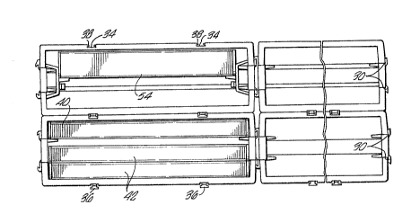
Figure 3 illustrates the vertical and horizontal
interconnecting means of the present invention, the
compact disc boxes and an audio cassette tape box.
Figure 4 is a cross-section through the module
illustrating the position of the cassette insert.
Figure 5 is another view of the cassette insert to
accommodate the storage of two audio cassette tape boxes.
Figure 6 is a cross sectional view of the module with
the right element chosen to accommodate the storage of
three single compact disc boxes.
Figure 7 shows the removable shelf illustrated ~n
position in Figure 6.
Figure 8 is a section view taken along line 8-8 in
Figure 7 showing the rib on the removable shelf.
2~8~0
Detailed Description of the Preferred Embodiment
Referring to the Figures, the multiple media storage
container and interconnecting system is shown. The
standard sized module 10 is shown in an exploded view in
Figure l and in its assembled state in the preferred
embodiment in Figure 2. The module 10 is assembled from
the cap 12 and the bottom 14 which together form the back
wall 16. The sides of the module 10 are formed by
connecting the right element lB and the left element 20 to
the cap 12 and bottom 14 by a series of connectors 22 and
receiving ports 24. This is shown in Figure 1. The
various electronic media are inserted into the module
through the front aperture 26. In the preferred
embodiment as illustrated in Figures 1 and 2, a lip 28
surrounds the front aperture 26. Within the scope of this
invention is the use of a module 10 made of a unitary
molded plastic piece in place of the various
aforementioned components.
The interconnected media storage system is formed by
connecting together numerous modules 10 in both the
horizontal and vertical directions by a horizontal and
vertical interconnecting means which is illustrated in
Figure 3. As shown in Figures 1 and 2, the modules 10 may
be horizontally interconnected relative to one another by
a rail means 30 positioned on one lateral side of the
module 10 which engages a complementary channel 32 on the
opposing lateral side of an adjacent module lO by simply
sliding the rail means 30 into the channel 32 on the
adjacent module 10.
The modules 10 are connected together in the vertical
direction relative to one another by a series of grooves
34 on the exterior surface of the cap 12 and into which a
plurality of T-shaped projections 36 from the adjacent
module will slide. These T-shaped projections 36 extend
out from the exterior surface of the bottom 14 and are
illustrated in Figures 3 and 4. A plurality of flanges 38
extend over the grooves 34 and correspond to the position
2 ~
of the T-shaped projections 36 to hold them in the
vertical direction.
As shown in Figures 2 and 3, the module 10 is sized
and shaped to accommodate the storage of one single
compact disc box 40 and one standard dual compact dlsc box
42. The compact discs 40 and 42 are stored at different
levels or compartments, or stored in a compartmentalized
manner, in the module 10 by a pair of shelves 44
positioned opposite one another on the right and left
elements 18 and 20. ~he spacing between the interior
surface of the cap 12 and the shelves 44 is approximately
the thickness of a single compact disc box 40. The
spacing between the interior surface of the bottom 14 and
the shelves 44 is approximately the thickness of a
standard dual compact disc box 42. The compact discs 40
and 42 are secured within the module 10 by engaging at
least one pair of first biased spring means 46 which are
biased inwardly to contart the compact discs 40 and 42
when moved into position on the shelves 44.
The module 10 may be adapted to house three single
compact disc boxes 40 by the attachment of a pair of
removable shelves 48 onto the right and left elements 18
and 20. The removable shelves 48, shown in Figure 7, may
be positioned as is illustrated in Figure 6, so that the
shelves 44 and the removable shelves 48 can store the
three single compact discs 40 at three different levels in
a compartmentalized fashion within the module 10. In the
preferred embodiment, a series of recessed notches 50 are
located on each of the right and left elements 18 and 20.
The removable shelves 48 are coupled to their respective
right or left elements 18 or 20 by attaching a portion of
the removable shelves 48 into the respective recessed
notches 50. Both of the removable shelves 48 may have at
least one rib 52 thereon to securely hold the shelf 48 in
place in the recessed notch 50.
The module 10 may also by adapted to house two
standard audio cassette boxes 54. This is accomplished by
2 ~
attaching a pair of cassette inserts 56 onto the
respective right and left elements 18 and 20 as
illustrated in Figure 4. The cassette insert 56 is
comprised of a second biased spring means 58 and a
cassette shelf 60 to secure the cassette boxes 54 in the
module 10 as shown in Figure 5. End stops 62 are also
provided on the ends of the second biased spring means 58
to abut up against the cassette boxes 54. This is a
necessary adaptation because the cassette boxes 54 are
generally of a shorter length than the compact disc boxes
40 and 42. The cassette inserts 56 may be coupled to the
right and left elements 18 and 20 by a series of
complementary tabs 64 which are releasably attached to a
plurality of connecting slots 66 on the right and left
elements 40 and 42. The scope of this invention includes
the adaptation of the module 10 to also store electronic
media, including the respective packaging, other than
compact disc boxes or audio cassette boxes.
Thus, a multiple media storage container and
storage system is disclosed. While embodiments and
applications of this invention have been shown and
described, it would be apparent to those skilled in the
art that many more modifications are possible without
departing from the inventive concepts herein. The
invention, therefore, is not to be restricted except in
the spirit of the appended claims.