Note: Descriptions are shown in the official language in which they were submitted.
2~81~70
-- 1 --
S P E C I F I C A T I O N
"METHOD OF MANUFACTURING ELECTRONIC DEVICE AND
APPARATUS FOR MANUFACTURING THE SAME"
TECHNICAL FIELD
This invention relates to a method of manufacturing
electronic devices such as a color filter for use in a
liquid crystal display device, a heat insulating layer
for use in a thermal printing head, and a multi-layer
circuit substrate for use in a hybrid IC, and a
manufacturing apparatus for effecting the method, and
more particularly to a method of manufacturing an
electronic device which employs various smooth patterns
or flat resin layers directly formed on a substrate or
formed on the same with another layer interpcsed there-
between, and an apparatus for effecting the method.
BACKGROUND ART
A color liquid crystal display device is one of
typical electronic devices. The structure of the
display device will be explained as an example. In the
device, a color filter is provided on one side of a liq-
uid crystal layer. A printing method can be used to
manufacture the color filter. In this method, color
inks dispersed pigments in a resin solvent are printed
on a transparent glass substrate in the shape of dots or
stripes. This method is suitable for lowering the
re~uired cost and increasing the mass productivity.
,
2~ 70
- 2 -
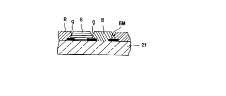
Specifically, in the prin-ting method, color inks,
red (R), green (G), and blue (B), àre printed on a glass
substrate in the shape of a desired pattern, by means o~
a gravure offset printing system equipped with a
blanket of a cylinder press type. Fig. 1 is a cross
sectional view of a color filter obtained after printing
and drying treatments. As can be understood from
Fig. 1, first, a light-insulation black layer BM is
forrned on a glass substrate 21 in the shape of a matrix.
lQ Then, a stripe of a red ink layer R is printed in one of
the regions in which the black layer BM is not formed
substantially, by rotating the cylinder press-type
transfer blanket and moving the same from the to the in
the figure. Subsequently, a green ink layer G is
printed in that region located adjacent to the region
coated with the red ink layer R which is not coated with
the black layer 3M substantially, and then a blue ink
layer B is printed in a manner similar to the above. As
is shown in Fig. 1, the surface of each of the three
color ink layers is arcuate in a state in which the lay-
ers are printed on the glass substrate. In other words,
the thickness of each color ink layer is minimum at its
both opposite boundary regions, and maximum at its cen-
tral region.
In this state, unevenness in color may be caused,
and therefore a color liquid crystal display of high
quality cannot be obtained. Thus, it is necessary -to
.. ~ , . . :
.. ~ - - . . . .
.: , : . ~ . -
- ~ . ,, : . . -
~ 2081 ~70
-- 3
make smooth the surface of each color ink la~er.
Various methods of smoothing the uneven sur~aces o~
resin layers have been proposed. As one of those
methods, a method of smoothing the surfaces of color ink
layers by means of a wrapping film having fine particles
is known from Published ~nexamined Japanese Patent
Application No. 61-3122. Further, according to another
method as disclosed in Published Unexamined Japanese
Patent Applications Nos. 63-216028 and 1-167807, the
convex portions of color ink layers are beated and then
smoothed by pressing with the use of a rubber or a
planished metal roller. Moreover, Published Unexamined
Japanese Patent Applications Nos. 2-251816 and
62-280805 disclose a method of smoothing color in~ lay-
ers formed on the glass substrate of a color filter, bybringing the layers into contact with a flat plate or a
machine plate, directly or with a releasable film
interposed therebetween, and pressing by the use of a
press roller or the machine platen from the side of the
glass substrate.
Specifically, in the method disclosed in Published
Unexamined Japanese Patent Application No. 62-280805, as
is shown in Fig. 2, color ink layers R, G, and B of a
color filter are brought into contact with a machine
platen 22, and are pressed with a press roller 23 placed
on the reverse side of a glass substrate 21. Further,
these publications disclose a method of applying,
. .
, . :, .., , , -
.,, :, .
~81570
-- 4
between the machine platen 22 and color ink laye~s, a
film not liable to stick thereto or a releasing ayent,
and a method of rotating and moving the press roller 2~.
PROBLEM THE INVENTION TO SOLVE
The above-described conventional methods are advan-
tageous in that the entire color-ink-coated surface is
uniformly pressed, and hence uniformly smoothed.
However, since a pressure is applied from the side of
the glass substrate, and is applied indirectly to the
color ink layers, it is necessary to apply such a low
pressure as will not break the glass substrate.
Especially, the glass substrate is liable to be broken
when it is pressed by a press roller. Thus, in such a
case, a further lower pressure must be applied. On the
other hand, in the method of pressing the substrate by
the use of a flat platen, though the substrate is not
easily broken, a rather high pressure is required for
satisfactorily pressing the entire surfaces of color ink
layers. Thus, in those methods, gaps ~ may remain be-
tween the color ink layers. These gaps g may cause, at
thP time of assembling of a liquid crystal display
device, gaps or babbles between the glass substrate and
another glass plate for forming electrodes or glass
deflection plate, or may make it impossible to adhere
such glass plates to each other accurately. Moreover,
in a case where a transparent conductive ITO fi].m
(indium-tin oxide film) is formed by sputtering on color
. : , I ~ , . . .
. v
,
2081~70
-- 5
ink films adhered to a filter substrate, direc-tl~ or
with an overcoat layer interposed therebetween, if the
surfaces of color ink layers are uneven, sputtering may
be insufficiently performed or no sputtering may be per-
formed on thick portions of the surfaces of the colorink layers, resulting i.n wire breakage. This may
adversely affect manufacture of an electronic device or
the characteristics of the same. In addition, light
scattering due to unevenness of the surfaces of color
ink films may reduce light transmission or cause other
optical losses.
To completely eliminate such gaps ~ from the
surfaces of color ink layers, a higher pressure must be
applied, or press -treatment mus~ be continued a rather
long time. This is disadvantageous in view of produc-
tivity, since it requires complex control of the tem-
perature of the color ink layers and the viscosity of
them. Further, though application of a releasable film
between a platen and color ink layers is effective, it
may, on the other hand, allow air to remain in
depressions existing between the color ink layers, which
causes cavities in the layers or unevenness of the
surfaces of them, or causes stripes to be formed on the
surfaces due to forcible exhaustion of the air remaining
in the depressions.
As described above, the conventional manufacturing
methods and apparatuses have defective points to be
- , :: . : : . .,
, . ., :.:, ~ : .. .
2~8~70
-- 6
improved, though they have not a few advantages.
DISCLOSURE OF T~ INVENTION
It is the object of the invention to provide a
method of manufacturing an electronlc device with a
smooth resin layer at a relatively high speed by apply-
ing a relatively low pressure, and to provide a manuf-
acturing apparatus for effecting the method therein.
The invention provides an electron device-
manufacturing method comprising the steps of applying a
resin coating layer, containing a solvent, to one of the
surfaces of a substrate, directly or with a layer inter-
posed therebetween; drying the resin coating layer to
remove the solvent; and heating and pressing the resin
coating layer to smooth the surface of the same. The
method is characterized in that in the step of smoothing
the surface of the resin coating layers, that side of
the substrate on which the resin coating layer is not
coated is mechanically supported by a supporting member,
and a heating roller is brought into contact with the
resin coating layer to press and heat the same, with
another resin film interposed therebetween, which is
thinner than the resin coating layer to be s~oothed,
thereafter releasing the interposed resin film.
The invention also provides an electron device-
manufacturing apparatus comprising: a supporting memberfor mechanically supporting that side of a substrate to
be treated which is opposite to a side on which a resin
- ~ ~ . ~- . . . ~ -
- . ;, - ~ .
..
2081~70
coating layer is provided with a layer interposed
therebetween; a heating roller located opposed to a
substrate-supporting portion of the supporting member,
and being rotatable while heating and pressing the resin
coating layer on the substrate; supply means for
supplying a thin resin film between the heating roller
and the resin coating layer on the substrate supported
by the supporting member; and releasing means for
releasing the resin film applied on the resin coating
layer on the substrate.
The above electron device-manufacturing method and
apparatus can produce, by applying a relatively low
pressure, an electron device which has a very smooth
resin coating layer. Though another resin filrn is
interposed between a heating roller and a resin coating
layer to be smoothed, the interposed resin film is much
thinner than the substrate, and hence the invention can
provide an effect substantially the same as that obtain~
ed by directly pressing the resin coating layer with the
heating roller. Thus, the resin coating layer is
pressed while being efficiently heated to a temperature
substantial]y identical to its softening point. That
is, the smoothing treatment is performed at a high ther-
mal efficiency with a relatively low pressure, thereby
increasing the treatment speed and mass productivity.
~urther, the resin layer is disposed to obliquely
contact the resin coating layer to be smoothed,
.. .. . .
: . .
2081~70
-- 8
and to be obliquely pulled up after the entire surface
of the resin coating layer is smoothed, thereby being
instantly released from the coating layer. Therefore,
no air will remain in the surface of the coating layer,
and hence unevenness of the surface due to remaining air
will not be found. Also, no wrinkles or the like will
be caused on the surface, resulting in a very smooth
resin coating layer.
BRIEF DESCRIPTION OF THE DRAWINGS
Fig. 1 is an enlarged cross sectional view, showing
an essential part of a general color filter in a manu-
facturing process by printing method;
Fig. 2 is a cross sectional view, showing an essen-
tlal part of a smoothing process per~ormed after the
1S process of Flg. 1;~
Fig. 3 1s a cross sectional view, showing an essen-
tial part of a structure obtained after the smoothing
process of Fig. 2;
Fig. 4 is a perspective view, showing an essential
part of a manufacturlng method and a manufacturing
apparatus according to a first embodiment of the inven-
tion;
Fig. 5 is a schematic side view, showing another
embodiment of the 1nventlon;
Fig. 6 is a~longltudinal sectional view, showing an
essential part of a color filter obtained by the embodi-
ments of the invention;
' ! . ,~
2081~70
Fig. 7 is a schematic side view, showing a furkhe~
embodiment o~ the invention;
Fig. 8 is a schematic side view, showing another
embodimant of the invention;
Fig. 9 is a schematic side view, showing a further
embodiment of the invention;
Fig. 10 is a schematic side view, useful in
explaining the initial stage of the operation of the
apparatus shown in Fig. g;
Fig. 11 is a schematic side view, showing an opera-
tional stage next to that shown in Fig. 10;
Fig. 12 is a schematic side view, showing an opera-
tional stage next to that shown in Fig. 11;
Fig. 13 is a schematic side view, showing an opera-
tional stage next to that shown in Fig. 12;
Fig. 1~ is a schematic side view, showing an opera-
tional stage next to that shown in Fig. 13;
Fig. 15 is a view, showing continuous operation of
each roller employed in the apparatuses shown in
Figs. 10 - 14; and
Fig. 16 is a schematic side view, showing a further
embodiment of the invention.
BEST MODE OF CARR~ING OUT THE INVENTION
(Embodiment 1~
Fig. 4 is an enlarged view, showiny part of an
embodiment in which the invention is applied to a method
of manu~acturing a color filter for use in a color
~,
- :
- . .
.:
. , .
2~81~70
-- 10 --
liquid crystal display, and to an apparatus for rnanufac~
turing the color filter.
First, light-insulation layers BM made of chrome
were provided in the form of matrix on a reckangular
transparent glass substrate 31 having a length of 32 cm,
a width of 30 cm, and a thickness of 1.1 mm. Then,
the surface of the substrate was washed, and a color
ink layer 32 was printed on the substrate in the shape
of stripes according with the intaglio cell pattern
by using a gravure offset printer, using color inks
containing a epoxyresin-based varnish as a main
component, a pigment, and a solvent. The color ink
layer 32 was formed by successively printing a red (R)
layer, a green (G) layer, and a blue (B) layer. Always
center of these ink layers appear conves since they had
viscosity. The thic~ness of the swollen portion is 4 -
5 ~m.
After forming the color ink layer 32, drying treat-
ment was performed at a temperature falling within a
range of 100 - 150~C, at which the layer will not be
thermo hardened, thereby removing part of the solvent.
The amount of that part of the solvent which is removed
is not less than 60 % of the entire solvent, and more
preferably not less than 80 %. If the removal amount is
not more than 60 %, air caused by evaporation of the
solvent may flow into the film when the film is
smoothed.
~::
-
. . .
2081~70
After printing and drying treatments, the color
filter was placed on a heating plate 33, wi-th its glass
substrate 31 kept in contact with the plate by means of
a vacuum chuck (not shown). A heater 3~ was buried in
the plate 33, and kept the surface of the same at a
predetermined temperature. A heating/pressing roller 38
was provi~ed above the plate 33, and had a built-in
heater (not shown) for keeping the surface of the roller
at 80 - 120~C. The roller 38 had a diameter of 12 cm,
was made of silicon rubber having a surface JIS-A hard-
ness of 70, and a surface roughness Ra of not more than
0.1 ~m. The surface hardness of the roller preferably
falls within a JIS-A hardness range of 40 - 90, though
an optimal hardness is determined also in view of the
hardness of a resin component contained in the ink. If
the hardness is lower than JIS-A hardness ~0, it is dif-
ficult to make the surface roughness of a smoothed color
ink film not more than 0.1 ~m. On the other hand, if
the hardness is higher than JIS-A hardness 90, glass
will easily be broken.
A resin film 35 was interposed between the color
ink layer 32 and roller 38. The film 35 consists of a
polyethylene telephthalate (hereinafter called "PET")
film 36 having a thickness of 10 - 50 ~m, e.g. 25 ~m,
and a silicone-based releasing layer 37 having a
thickness of l ~m or less, e.g. several thousands
angstroms, and applied on the lower surface of the PET
. - , ~ -
'' ' ' ~ ., ~ ~
20815s,-7,,D
- 12 -
film. While the color ink layer 32 was being heated at
about 90~C, the heating roller 38 was pushed down in
the direction indicated by the arrow Fa to press the
layer 32, and simultaneously the roller 38 was rotated
in the direction indicated by the arrow Fb and the plate
33 is moved in the direction indicated by the arrow Fc.
That is, the color ink layer 32 was continuously
smoothed in the longitudinal direction, i.e., in the
direction Fc, by the roller 38. In this smoothing
process, the resin film 35 was located such that it
could contact the layer 32 at a certain angle. As a
result, the layer 32 was smoothed by the roller 38,
while air e~isting in depressions of the layer 32 was
being pushed out. A preferable angle between the sur-
15 faces of the color ink layer 32 and the resin film 35falls within a range of 5 - 80 ~C . The portion of the
layer 32 which had been smoothed by the heating roller
38 and was coated with the resin film 35 was heat-
insulated, and hence it was prevented from uneven dis-
20 tribution of temperature. This prevents wrinkles or thelike from being caused on the surface of the color ink
layer 32 in a later releasing process. The heating
roller 38 applied a pressure of 10 - 15 Kg/cm to the
film 32, and the heating plate was moved at a speed of
25 5 - 8 cm/min.
Immediately after smoothing the entire surface of
the layer 32, the resin film 35 was instantly released
,~
2081~1p
- 13 -
from the layer 32 by being moved upward at an angle wi-th
the use of a releasing roller (no-t shown). Thereafter,
the glass substrate 31 of the color filter was detached
from the plate 33, and was sub~ected to heat1ny at
200 - 250~C for several hours, thereby thermo hardening
the color ink layer 32. Thus, a color filter having the
color ink layer 32 whose surface 32a was smoothed as
shown in Fig. 6 was obtained. The thickness of the
smoothed color ink layer 32 was 3.0 ~m.
The pattern of the color ink layer is not limited
to a stripe pattern as above, but may be a pattern in
which rectangular color elements are aligned regularly.
Also in this case, it is desirable to smooth the layer
by moving the rotating heatlng roller in the longitudi-
nal direction of the color elements. Further, square or
circular color elements may be employed. In these
cases, the direction of smoothing is optional.
(Embodiment 2)
Fig. 5 shows an apparatus for performing an effec-
tive and continuous treatment. This apparatus has a
plurality of supporting rollers 40, a lower-surface-
heating roller 39 provided at a predetermined location,
a film-releasing roller 42, and a belt conveyer 41
provided on these rollers. The glass substrates 31 of
color filters to be smoothed are placed on the belt con-
veyer 41 at regular intervals. An upper-surface-
heating/pressing roller 38 is located above the heating
,
.
', : .-
' ", , ':, : . .' . . '
.. . .
~8~570
- 14 -
roller 39. A preliminary heating furnace 43 is provided
upstream of the rollers 38 and 39, ~or preliminarily
heating the color filters. A resin film 35 coated ~ith
a releasing agent is disposed such that it is forwar~ed
from the film-forwarding roller 45 and wound by a film-
winding roller 47 through the upper roller 38 and the
film-releasing roller 46. Also in this embodiment, the
resin film 35 is disposed to obliquely contact the color
ink layer 32 to be smoothed. The heating roller 38 and
film-releasing roller 46 are arranged in a single dimen-
sion, thereby keeping the resin film 35 on that portion
of the color ink layer 32 which has been smoothed. The
above-described structure is employed also in other
embodiments, hereinafter referred to. Further, in this
embodiment, a cooling ~un 44 is provided between the
heating rollers 38, 39 and the film-releasing rollers
42, 46, for cooling color filters after the smoothing
treatment.
After the smoothing treatment, the glass substrate
31 with the color ink layer 32 is cooled durlng passing
under the cooling fun 44, and then the resin film 35 is
continuously released from the color filter placed on
the moving conveyer by means of the film-releasing
roller 46 and the film-winding roller 47 located at an
angle above the roller 46.
Thereafter, ink is thrmo hardened, thereby provid-
ing a color filter having the surface 32a smoothed, as
: . :
.
208~70
is shown in Fig. 6. Then, an ITO film serviny as an
opposed electrode of the liquid crystal display appara-
tus is formed directly on the color ink f:Llm 32, or is
formed thereon with an overcoat layer interposed
therebetween. Moreover, in the invention, the color ink
layer 32 has a high smoothness, and hence good optical
and electrical characteristics can be obtained without
forming the overcoat layer.
~Embodiment 3)
In the apparatus shown in Fig. 7, the glass
substrate 31 of a color filter is placed on a flat
heating plate 33 by vacuum pressure. A heating roller
38 is moved on a color ink layer 32, while rotating and
pushing the same with a resin film 35 interposed there-
between, thereby smoothing the layer 32. The resin film
35 is disposed to pass a movable film-releasing roller
48 located in an extension line of the surface of the
layer 32, and then to be wound by a winding roller 47.
After the entire surface of the layer 32 is smoothed by
the heating roller 38, the movable film-releasing roller
48 is moved up, thereby obliquely pulling up the resin
film 35 to release the film 35 from the layer 32.
(Embodiment 4)
In the apparatus shown in Fig. 8, a first belt con-
veyer 49, a second belt conveyer 50, and a third belt
conveyer 51, which are movable in a direction indicated
by the arrow Q, ale arranged in a single dimension with
: : : , ~ ,
. : :
:
2081~70
predetermined intervals between the conveyers ~9 and 50
and between conveyers 50 and 51. The first belt
conveyer 49 transfers a glass substrate 31 with that
resin film or color ink layer 32 which has not been
smoothed yet. The second belt conveyer 50 transfers the
substrate 31 in a smoothing process, and the third belt
conveyer 51 transfers the substrate 31 after the
smoothing process. An infrared heating device 45 for
preliminary heating is provided above the first belt
conveyer 49. A lower supporting roller 39 for driving
the second belt conveyer 50 cooperates with an auxiliary
roller 39a to support the conveyer 50, and serves also
as a heating roller. An upper heating/pressing roller
38 provided above the lower heating/supporting roller 39
can move in the vertical direction Fa, to a position 38a
indicated by the broken line. Similarly, a movable
film-releasing roller 48 can move in the vertical direc-
tion Fd, to a position 48a indicated by the broken line.
A film-forwarding roller 45 made of plastic and wound
with a resin film 35 is located at an angle leftward
above the upper heating roller 38. A roller 52 for pre-
venting meandering of the film 35 is provided between
the film-forwarding roller 45 and heating roller 38.
The rollers 45 and 52 form a resin film supply 45a. The
roller 45 is provided with a driving device for driving
the roller 45 in a reverse direction, a damping mecha-
nism, a powder brake, etc., and is controlled by
.
~ ' '
2~ 70
a control device. Also in this embodiment, the resin
film 35 is disposed to be able to obliquely contact the
color ink layer 32 to be smoothed. A film-pulling
roller 53, serving also as a meandering preventing
roller, and a winding roller 47 for winding the resin
film 35 are provided at an angle rightward above the
film-releasing roller 48. The winding roller 47 has a
torque motor, and a damping mechanism, and is controlled
by a control device.
To smooth the resin layer by the use of the above
apparatus, the glass substrate 31 of a color filter is
placed on the belt conveyer 49, with that resin layer or
color ink layer 32 of the filter which is to be smoothed
facing upward. Preliminary heating is performed using
the infrared heating device 3. When the glass substrate
31 is transferred onto the second belt conveyer 50, the
heating/pressing roller 38 is mov~d downward, and con-
tacts the color ink layer 32 on the substrate 31, with
the resin film 35 interposed therebetween. The roller
38 presses the layer 32 with a predetermined force from
upward, and rotates in synchronism with the rotation of
the belt conveyer 50. The film-releasing roller 48 is
located in an extension line of the surface of the color
ink layer 32. When the roller 48 is moved on the
substrate 31, the resin film 35 is pulled at a given
speed from upward at an angle, and is released from the
substrate 31. The pulled resin film 35 is wound by the
- ~ ~
. - . ~ :
20~7~
- 18 -
winding roller 47. During the above opera-tion, a
tensile force acting upon the resin film 35 is
controlled by the driving device for reverse rotation
and damping device employed for the film-Eorwarding
roller 45, and the torque motor and damping mechanism
employed for the windiny roller 47. Thus, the resin
film 35 is prevented from being thermally expanded,
thereby avoiding occurrence of wrinkles on the color ink
layer 32 due to thermal expansion of the resin film 35.
This embodiment is performed under the following
conditions with the use of the following materials:
Color ink: mainly consisting of an epoxy resin-
based varnish containing an organic pigment and a
solvent;
Drying temperature of the color ink film:
70 - 110~C;
Resin film: consisting of a biaxial PET having a
thickness of 25 - 40 ~m and coated with a releasing
agent made of addition-type silicone;
Smoothing conditions:
Preliminary heating temperature ... 85 - 100~C
Temperature of the heating roller ...85 - 100~C
Pressure (linear pressure) ... 10 - 15 Kg/cm
Forwarding speed ... 5 - 8 cm/min
(Embodimen-t 5)
In the apparatus shown i.n Fig. 9, a heating plate
33 is disposed on a bel-t conveyer 54 immovable in the
:
20~1~7~
-- 19 --
vertical direction, and a glass substrate 31 printed
with a color ink layer 32 is placed on the plate 33.
The substrate 31 and layer 32 are heated by the heating
plate 33. The apparatus also employs a resi~ film sup-
ply ~5a, a resin film 35, a heating/pressing roller 38,a film--releasing roller 48, and a film-winding roller
47, which are similar to those shown in Fig. 8.
However, a pair of rollers 55 and 56 are provided down-
stream of the film-releasing roller 48, and a movable
film-pulling roller 53 is provided downstream of the
rollers 55 and 56. The resin film 35 is supported by
the roller 53. The roller 53 can move to a position 53a
indicated by the broken line. The film-releasing roller
48 and pulling roller 53 cooperate to effectively and
instantly release the resin film 35 from the color ink
layer 32 having been smoothed, as will be explained
hereinafter.
The structure of Fig. 9 may be modified such that
the roller 53 is used to prevent meandering of -the film
35, and that the roller 56 is movable to function as a
film-pulling roller. In this modification, it is more
desirable to wind the resin film 35 counterclockwise
onto the roller 55 from below, wind clockwise onto the
pulling roller 56, wind counterclockwise onto the roller
53, and make the puliing roller 56 movable to a position
53a indicated by the broken line.
The operation of the apparatus of Fig. 9 will be
-~ ,
- ~ :
2~81~70
- 20 -
explained with reference to Figs. 10 - 15.
As is shown in Fig. 10, the glass substrate 31 on
which the color ink layer 32 is printed is held on the
heating plate 33 by using vacuum pressure, with the
5 layer 32 facing upward, and is heated at all times.
Until the heating plate 33 reaches the heating/pressing
roller 38, the roller 38 and film-releasing roller 48
are kept up. When the plate 33 reaches a position just
this side of the heating roller 38 at a time point of A
(in Fig. 5), the winding roller 47 is rotated to forward
the resin film 35 to the right in Fig. 9, thereby
bringing that portion of the resin film 35 which has not
been used yet into contact with the color ink layer 32
to be smoothed.
Thereafter, at a time point of B at which the
heating plate 33 reaches under the heating roller 38,
the heating roller 38 and film-releasing roller 48 are
moved down, to press and smooth the color ink film 32
with a predetermined force at a time point of C, as is
20 shown in Fig. 11. During pressing and smoothing the
film 32, the resin film 35 is moved rightward in accor-
dance with movement of -the plate 33 and rotation of the
roller 38, as is shown in Fig. 12. ~he forwarding
roller 45 and winding roller 47 supply the resin film 35
25 with an appropriate tensile force which absorbs thermal
expansion thereof.
After the entire surface of the color i.nk layer 32
,
.
2081~70
of the glass substrate 31 is smoothed, the film-
releasing roller 48 is moved upward and the pulling
roller 53 is moved to the left from the position 53a at
a time point of D, thereby strongly pulling ~pward the
resin film 35 from a portion corresponding to an end of
the color ink layer 32 remote from the heating roller
38, to a portion corresponding to the other end of the
same, to instantly release the resin film from the color
ink layer. The apparatus according to this embodiment
may be modified such that no pulling rollers are
employed, and that the winding roller 47 is rotated
momentarily at high speed in the forward direction,
thereby imparting a strong tensile force to the resin
film to release the same. Where the releasing speed was
set to 0.2 - 1 sec~for a color ink film bei.ng 25 cm from
one end to the other end, no wrinkles were found on the
color ink film obtained after the smoothing treatment.
Therefore, it is desirable to set the film releasing
speed to 0.8 - 4 sec/m.
As is shown in Fig. 14, at a time point of I after
releasing, the pulling roller 53 is returned to the
original positioni and the heating roller 38 and film-
releasing rolIer 48 are moved up, thereby subjecting the
next color filter placed on another heating plate 33~,
to the smoothing treatment. This operation is automati-
cally repeated by the use of a sequence control device
employing a known micro computer, and mass production
2~81570
- 22 -
can be made at a relatively high speed.
tEmbodiment 6)
In the apparatus shown in Fig. 16, a heating pla~e
33 is fixed in position, and a heating/pressing roller
38 located above the plate 33 is moved while being
rotated, to thereby smooth a color ink layer 32 on a
glass substrate. A resin film 35 is located obliquely
to the surface to be smoothed. A film-releasing roller
48 is located in an extension line of the surface of the
color ink layer 32, and is kept in contact therewith
during the layer 32 being smoothed. After the entire
surface of the layer 32 is smoothed, the film-releasing
roller 48 is moved up, and a pulling roller 53 is moved
leftward, thereby obliquely pulling the resin film from
a portion corresponding to an end of the color ink layer
32 remote from the heating roller 38, to a portion
corresponding to the other end of the same, to instantly
release the resin film.
Though the above-described apparatuses are applied
to a color filter for use in a color liquld crystal
display device, the invention is not limited to this,
but may be applied to other electron devices in which it
is necessary to smooth various patterns attached to a
substrate, directly or with a layer interposed therebe-
tween, or to smooth a flat resin layer. The followingembodiment is an example of such application.
-, :..
~ : . . :
,;
... .
208~570
- 23 -
(Embodiment 7)
To manufacture a thermal printiny head usiny a
metal substrate, a metal substrate made of an Fe alloy,
which contains 16 - 18 % by weight of Cr and has a
thickness of 0.5 mm, was prepared. The substrate was
dipped in dilute sulfuric acid (an aqueous solution con-
taining 5 ~ 20 % by volume of 96 % H2SO4) for
1 - 2 minutes, thereby activating the surface thereof.
Thereafter, polyamic acid, precursor of polyimide serv-
lQ ing as a rasin layer, was coated on one of the surfacesof the substrate in the form of stripes. Part of a
solvent contained in the coated layer was removed at a
temperature of 60 - 120~C at which polyamic acid would
not changed to polyimide. Then, smoothing treatment was
performed by the use of an apparatus and method accord~
ing to any of the above-described embodiments. The
conditions of the smoothing treatment was as follows:
Resin film: consisting of a biaxial PET having a
thickness of 20 - 50 ~m and coated with a releasing
agent made of addition-type silicone;
Smoothing conditions:
Preliminary heating temperature ... ~0 - 90~C
Temperature of the heating roller ...90 - 105~C
Pressure (linear pressure) ... 10 - 15 Kg/cm
Forwarding speed .... 5 - 8 cm/min
Resin film-releasing speed: 1 - 3 sec/m
" 2~8157~
- 24 -
(Advantages of the Invention)
As is explained above, the inven~ion can provlde,
applying a relatively low pressure, an electron device
having a very smooth resin coating layer. Though, in
the invention, another resin layer is interposed between
a heating roller and a resin coating layer to be
smoothed, the interposed resin layer is very thin, and
hence the invention can provide an effect substantially
the same as that obtained by directly pressing the resin
coating layer with the heating roller. Thus, the resin
coating layer is pressed while being efficiently heated
to a temperature substantially identical to its soften-
ing point. That is, the smoothing treatment is per-
formed at a high thermal efficiency with a relatively
low pressure, thereby increasing the treatment speed and
mass productlvity. Further, the resin film is disposed
to obliquely contact the resin coating layer to be
smoothed, and to be obliquely pulled up after the entire
surface of the resin coating layer is smoothed, thereby
being instantly released from the coating layer.
Therefore, no air will remain in the surface of the
coating film, and hence unevenness of the surface due to
remaining air will not be found. Also, no wrinkles or
the like will be caused on the surface, resulting in a
very smooth resin coating layer.
.
: . ~ - .:
- ~ , - , :
~ .. . ~ :. . . . .