Note: Descriptions are shown in the official language in which they were submitted.
R~CK~-~OUND OF THE lN v~NllON
Field of the Invention: 2 0 8 1 6 2 ~
The present invention relates to a high-freguency power
divider and combiner, and more specifically to a circuit for
dividing and combining high-frequency power when a plurality
of power amplifiers are parallel-operated.
Description of the Related Art:
As power dividing and combining circuits for parallel-
operating power amplifiers and combining together ouL~Ls
produced from the power amplifiers so as to obtain large
power, there have heretofore been used a 3 dB coupler type
power divider and combiner, a Wil~incons power divider and
combiner, and an impe~nce transformer type power divider
and combiner.
In a power amplifying apparatus of a type wherein a
plurality of power amplifiers are parallel-operated to
generate GuL~L power, which is then combined so as to
produce large power, allowable ouL~uL power is often
controlled by changing the number of the power amplifiers.
A description will now be made, as an illustrative example,
of a case in which the input and ouL~uL imp~nce in
circuits are set to 50 Q, and wherein two, three or four
power amplifiers are parallel-operated to thereby control
allowable output power of a power amplifying apparatus.
-
208 1 628
a (~Jhen
With the 3 dB coupler type power divider and
combiner is used, the power can be efficiently divided
and combined only when the number of power amplifiers to
~ c~
be parallel-operated is 2n. On the other hand, wtt~ the
Wilkinson's power divider and combiner is used, the
power can be efficiently divided and combined when the
number of parallel operating power amplifiers is an even
number. In either case where the number of power ampli-
fiers to be parallel-operated is four, the power ampli-
fiers can be efficiently parallel-operated by using a 4-
way divider and a 4-way combiner. However, when the
number of the power amplifiers is reduced from four to
three or two, the power is used up by resistances as
dummy loads for absorbing unbalanced power, which are
used to obtain isolation between terminals of dividers
and between those of combiners. Therefore, a power loss
of about 2.5 dB is developed when the three power ampli-
fiers are used, whereas a power loss of about 6.0 dB is
developed when the two power amplifiers are used.
In order to efficiently divide the power and
combine it in 2-way combination form, it is necessary to
replace the divider and the combiner with a 2-way divid-
er and a 2-way combiner respectively. When the divider
and the combiner are replaced by others respectively,
the operation of a power amplifying apparatus should be
temporarily stopped. Therefore, the 3 dB coupler type
- 208 1 628
power divider and combiner and the Wilkinson's power
divider and combiner are not suited to a method of
making the change in the number of the units of the
power amplifiers to thereby adjust or control the allow-
able output power of the apparatus.
an
Accordingly,~impedance transformer type 4-way
divider and 4-way combiner will be shown in FIG. 6(A) as
one example. In FIG. 6(A), D indicates a power dividing
circuit (hereinafter called merely a "divider") and S
indicates a power combining circuit (hereinafter called
merely a "combiner"). In addition, A1 through A4 indi-
cate power amplifiers respectively. However, the imped-
ance transformer type divider and combiner, different
from the 3 dB coupler type power divider and combiner
and the Wilkinson's power divider and combiner, provide
no resistance as a dummy load for unbalanced power
absorption, but only an impedance matching function is
provided and hence no isolation is obtained between
terminals. Therefore, the isolation between adjacent
output terminals for outputs 1 through 4 of the divider
and the isolation between adjacent input terminals for
inputs 1 through 4 of the combiner are obtained from
either isolators or circulators provided at inputs and
outputs of respective power amplifiers Ai as shown in
FIG. 6(B).
The combiner S and the divider D are identical in
principle to each other. A description will therefore
208 1 628
be made of the combiner S as an illustrative example.
Transmission lines Ws1 through Ws4 each having an imped-
ance of 50 Q and a line length of n~/2 (where n = posi-
tive integer and ~ = wavelength of a used frequency) are
provided between the respective input terminals of the
combiner S and a combining point P thereof. Since the
lines of 50 Q impedance are 4-way combined, the imped-
ance at the combining point P is brought to 12.5 Q (= 50
Q/4)-
An impedance transformer is used to convert ortransform the impedance at the combining point P into
output impedance of 50 Q. For example, the impedance
transformer is composed of a transmission line Ws5
having the impedance of 25 Q and a line length of ~/4.
Incidentally, the divider D is also constructed in a
manner similar to the combiner S. In this case, trans-
mission lines Wdl through Wd4 correspond to the trans-
mission lines Ws1 through Ws4 and a transmission line
Wd5 serving as the impedance transformer corresponds to
the transmission line Ws5. By setting the combiner S
and the divider D in this way, a division loss is O db
whereas a combination loss is O dB, which result in the
total loss of O dB.
A description will now be made of a case in which
the control of allowable output power is carried out by
making a change in the number of power amplifiers. As
208 1 628
shown in FIG. 7, one of input terminals of a 4-way com-
biner S is opened and three power amplifiers are con-
nected in parallel to the corresponding input terminals
so as to produce the output of the 4-way combiner in the
form of 3-combination. The length of each of transmis-
sion lines, which extend from the power amplifiers Al,
A2, A3 to a combining point P, is n~/2. Thus, the
impedance as seen in the direction of the opened input
terminal of the 4-way combiner from the combining point
P is equivalently brought to infinity. Therefore, the
impedance at the combining point P reaches about 16.7 Q
(= 50 Q/3)-
Further, an impedance transformer, which extendsfrom the combining point P to the output terminal, is
constructed so as to transform 12.5 Q into 50 Q. Thus,
when this impedance transformer is used so as to trans-
form 16.7 Q into 50 Q, the reflection coefficient pro-
duced due to impedance mismatching is determined by the
following equation:
Reflection coefficient = (ZL-Z0)/(ZL+Zo)
= (16.7-12.5)/(16.7+12.5)
= 0.144
The reflection loss produced due to the impedance
mismatching is determined by the following equation:
Reflection loss = 10 log[l/(12-reflection
coefficient )] 2
= 10 log[1/(1-0.144 )]
= 0.09 dB
208 1 628
Thus, the reflection loss is brought to about 0.09 dB.
The divider D also gives rise to the reflection
loss in a manner similar to the combiner S. Therefore,
the reflection loss is doubled over the entire device,
that is, the reflection loss amounts to about 0.18 dB.
When the combiner S is used as a 2-combiner in the
same manner as described above, the impedance at a
combining point P is brought to 25 Q (= 50 Q/2) as shown
in FIG. 8. Therefore, the loss produced due to imped-
ance mismatching of an impedance transformer is brought
to about 0.5 dB. Thus, the loss in the combiner S and
the divider D reaches about 1.0 dB in total.
Even when the 4-way combiner is used as a 3-way
combiner or a 2-way combiner as described above, the
power combination can be made although only the mismatch
loss due to the impedance transformer is produced. The
input power division can also be carried out in a manner
similar to the power combination. However, a division
loss and a combination loss due to mismatching increase
when the number of divisions and the number of combina-
tions are reduced.
SUMMARY OF THE INVENTION
It is a general object of the present invention to
provide a high-frequency power divider and combiner
capable of dividing and combining power at a reduced
loss for use in a power amplifying apparatus in which a
-- 208 1 628
plurality of power amplifiers are parallel-operated and
the output power thereof is controlled by changing the
number of the power amplifiers.
In order to achieve the above general object, the
present invention provides, in a power amplifying appa-
ratus which includes high-frequency power amplifiers
parallel-operated in a range between M and N (M and N:
positive integers and M<N) both indicative of the number
of the power amplifiers and which makes a change in the
number of the parallel-operated power amplifiers to
thereby control output power, a high-frequency power
divider and combiner comprising a power dividing circuit
having an impedance transformer set in such a manner
that the power loss is minimized by assigning the in-
termediate number K (positive integer) between M and N
both of which indicate the number of divisions and
having N output terminals, and a power combining circuit
having an impedance transformer set in such a manner
that the power loss is minimized by assigning the in-
termediate number K corresponding to the number of
combinations and having N input terminals.
In order to achieve the above general object, the
present invention also provides a high-frequency power
divider and combiner wherein a plurality of transmission
lines serving as an impedance transformer each having a
predetermined impedance and a predetermined line length
are connected from respective input terminals of the
2081 628
combiner, the impedance transformation of the impedance
transformer is separately made between respective trans-
mission lines electrically connected to the correspond-
ing transmission lines and a combining point and an
impedance transformer is electrically connected to the
combining point so as to carry out the impedance trans-
formation.
The above and other objects, features and advan-
tages of the present invention will become apparent from
the following description and the appended claims, taken
in conjunction with the accompanying drawings in which a
preferred embodiment of the present invention is shown
by way of illustrative example.
BRIEF DESCRIPTION OF THE DRAWINGS
FIG. 1 is a block diagram showing the structure of
one embodiment of the present invention;
FIG. 2 is a block diagram illustrating the struc-
ture of the embodiment shown in FIG. 1, which is applied
to a 4-way division and a 4-way combination;
FIG. 3 is a block diagram depicting the structure
of the embodiment shown in FIG. 1, which is applied to a
2-way division and a 2-way combination;
FIG. 4 is a diagram showing the structure of a com-
biner wherein the impedance transformation of an imped-
ance transformer employed in the embodiment shown in
208 1 628
FIG. 1 is performed between respective input terminals
and a combining point and between the combining point
and an output terminal;
FIG. 5 is a diagram illustrating the structure of
another combiner wherein the impedance transformation of
the impedance transformer employed in the embodiment
shown in FIG. 1 is carried out between respective input
terminals and a combining point;
FIG. 6(A) is a block diagram depicting the struc-
ture of a conventional example illustrative of impedance
transformer type 4-way divider and 4-way combiner;
FIG. 6(B) is a block diagram showing the structure
of a conventional example in which isolation between re
spective output terminals of a divider and isolation
between respective input terminals of a combiner are
obtained by isolators I or circulators electrically
connected to inputs and outputs of respective power
amplifiers Ai;
FIG. 7 is a block diagram showing the structure of
the conventional example depicted in FIG. 6(A), which is
applied to a 3-way division and a 3-way combination; and
FIG. 8 is a block diagram illustrating the struc-
ture of the conventional example shown in FIG. 6(A),
which is applied to a 2-way division and a 2-way combi-
nation.
DETAILED DESCRIPTION OF THE PREFERRED EMBODIMENTS
`- 208 1 628
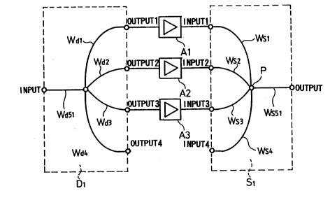
FIG. 1 is a block diagram showing the structure of
one embodiment of the present invention.
The present embodiment illustrates cases in which
the number of power combinations ranges from 2 to 4.
In the present embodiment, as shown in FIG. 1,
impedance transformer type 4-way divider and 4-way
combiner are constructed in such a manner that one of
input terminals and one of output terminals are opened,
power amplifiers A1, A2 and A3 are parallel-connected to
each other and the total power loss is minimized when
the output is represented in the form of a 3-way combi-
nation.
The 4-way combiner Sl and the 4-way divider D1 are
identical in principle to each other. A description
will therefore be made of the 4-way combiner S1 as an
illustrative example.
Let's now assume that the impedance and length of
each of transmission lines Ws1 to Ws4, which extend from
the power amplifiers Al to A4 to a combining point P,
are 50 Q and n~/2 respectively in a manner similar to
FIG. 6(A). Outputs of impedance 50 Q are 3-way combined
and result in the impedance of about 16.7 Q at the com
bining point P. An impedance transformer, which con-
verts, i.e., transforms the impedance of 16.7 Q at the
combining point P into the 50 Q output impedance, is
constructed of a transmission line Ws51 whose impedance
and length are 28.9 Q and ~/4 respectively.
-
208 1 628
When the 4-way combiner Sl is made up of three
parallel-connected power amplifiers and the output of
the 4-way combiner Sl is represented in the form of a 3-
way combination, the impedance as seen in the direction
of provision of the opened input terminal from the
combining point P of the 4-way combiner Sl is equiva-
lently regarded as infinite. Further, the loss of the
impedance transformer is zero. Since the output of the
4-way combiner Sl is represented in the form of the 3-
way combination as described above, no mismatching is
developed and the combination loss is theoretically O
dB.
Further, the 4-way divider Dl is also identical in
structure to the 4-way combiner Sl. Transmission lines
Wdl to Wd4 correspond to the transmission lines Wsl to
Ws4 and a transmission line Wd51 serving as an impedance
transformer corresponds to the transmission line Ws51.
Thus, the division loss is O dB and the sum of the
division loss and the combination loss is also O dB.
When the output of the above 4-way combiner Sl is
represented in the form of a 4-way combination as shown
in FIG. 2, another power amplifier is added to the three
power amplifiers shown in FIG. 1. In this case, the
power loss at the combining point P, which is developed
due to mismatching is brought to about 0.09 dB. Simi-
larly to the 4-way combiner Sl, 4-way divider Dl is also
208 1 628
constructed in such a manner that the power loss is brought
to about 0.09 dB. Accordingly, the power loss of the entire
apparatus reaches about 0.18 dB.
When the o~u~ of the above 4-way combiner Sl is
represented in the form of a 2-way combination as shown in
FIG. 3, one power amplifier is removed from the three power
amplifiers shown in FIG. 1 and the imp~nce at the combining
point P i8 brought to 25 n. In addition, the power loss due
to the mismatching of the imp~nce transformer is brought to
about 0.17 dB. Similarly to the combiner Sl, divider Dl
shown in FIG. 3 is also constructed in such a manner that the
power loss is brought to about 0.17 dB. Thus, the power loss
of the entire device reaches about 0.34 dB.
If the power loss is minimized as described above when
the input of the 4-way divider Dl is represented in the form
of 3-way division and the o~L~u~ of the 4-way combiner Sl is
represented in the form of a 3-way combination, then the
power combination can be made at a low loss when the number
of the power amplifiers to be parallel-operated is 4, 3 and
2. It is apparent that the power combination can be
performed at the low loss if the loss at the power
combination is compared with cases developed in the
conventional examples shown in FIGS. 6(A), 6(B), 7 and 8.
- 12 -
, .,
208 1 628
TABLE
Com~arison of losses conventional invention
parallel connected 4 power amplifiers 0 db 0.18 db
parallel connected 3 power amplifiers 0.18 d~ O db
parallel connected 2 power amplifiers 1.0 db 0.34 db
As seen in the above Table, there arises a prohibitive
power los8 in the conventional power divider-combiner,
particularly in the case where 2 power amplifiers are
parallel operated, whereas the power loss in the divider-
combiner of the present invention falls within a tolerable
range for every case including 2 to 4 power amplifiers.
When the divider and combiner according to the present
embodiment are now applied to a method of starting the
operations of two power amplifiers upon installation and
increasing the number of the power amplifiers in order of 3,
4, at a certain period after the installation of the two
power amplifiers so as to make an increase in the o~ L
power according to a demand, it is possible to increase the
number of power amplifiers at constant gain, and since it is
unne~cc~ry to make changes in the divider Dl and the
combiner Sl, the number of the power amplifiers can be
increased without temporarily inactivating the power
amplifiers. Further, the divider-combiner according to the
- 13 -
.~= .
` A
208 1 628
present invention can be applied to a case where an operation
is initiated with 4 power amplifiers connected in parallel
with each other, and thereafter, the number of the power
amplifiers is decreased to 3, and further to 2.
Therefore, the divider and combiner according to the
present embodiment are most suitable for use with, e.g., a
base station used to provide mobile telephone service, of a
type wherein the station is first operated by a small number
of power amplifiers upon installation and the number of the
power amplifiers is then increased successively so as to
increase power to be transmitted to mobile stations. If the
divider and combiner are employed in a system of a type where
in the transmission of a radio wave cannot be stopped even a
moment as in the base station, then an increase in the power
to be transmitted can be made by simply increasing the number
of the power amplifiers without stopping the transmission
even a moment. Even when a defect of malfunction arises with
any of the amplifiers being operated in parallel, it is
possible to maintain the constant gain operation by removing
the defective or malfunctioning power amplifier from the
system.
The above-described embodiment has shown, as an
illustrative example, a case in which the two to four
- 13a -
208 1 628
power amplifiers are parallel-operated. However, the
number of the power amplifiers to be parallel-operated is
not necessarily limited to these numbers and hence any
number of power amplifiers can be used. When the number
of power amplifiers to be parallel-operated ranges from
M to N, the impedance transformer may be constructed by
selecting the optimum value in such a manner that the
power loss is minimized by an intermediate number K
(positive integer) between M and N.
Incidentally, the above-described embodiment has
shown the combiner in which the impedance transformation
by the impedance transformer is carried out between the
combining point P and the output terminal. Further, the
present embodiment has also shown the divider in which
the impedance transformation is made between the input
terminal and the dividing point.
As shown in FIG. 4, however, the impedance trans-
formation can also be made between respective input
terminals and a combining point P and between the com-
bining point P and the output terminal. In the illus-
trated example, transmission lines Ws11, Ws12, Ws13,
Ws14 each of which has the impedance of 50 Q and a line
length of ~/4+n~/2, are connected from the respective
input terminals of the combiners. Further, an impedance
transformer is used to transform the impedance of 50 Q
into the impedance of 100 Q for each transmission line.
As an illustrative example, the impedance transformer is
14
208 1 628
composed of transmission lines Ws21, Ws22, Ws23, Ws24
each having an impedance of 70.7 Q and a line length of
~/4, which are electrically connected to their corre-
sponding transmission lines Ws11, Ws12, Ws13, Ws14 so as
to perform the impedance transformation.
Now, the impedance at the combining point P is
brought to 25 Q (= 100 Q/4). An impedance transformer
is used to transform the impedance of 25 Q at the com-
bining point P into that of 50 Q. For example, this
type of impedance transformer is constructed of a trans-
mission line Ws52 which has the impedance of 35.4 Q and
a line length of ~/4. Thus, the impedance transforma-
tion can be made between the respective input terminals
and the combining point P. The divider D1 can also be
treated in the same manner as the combiner.
As also shown in FIG. 5, the impedance transforma-
tion can also be carried out between respective input
terminals and a combining point P. In the illustrated
example, transmission lines Wsll, Ws12, Ws13, Ws14 each
of which has the impedance of 50 Q and a line length of
~/4+n~/2, are connected from respective input terminals
of the 4-way combiner. Further, an impedance transform-
er is used to transform the impedance of 50 Q into the
impedance of 200 Q for each transmission line. As one
example, this type of impedance transformer is composed
of transmission lines Ws31, Ws32, Ws33~ Ws34 each having
208 1 628
the impedance of 100 Q and a line length of ~/4, which
are electrically connected to their corresponding trans-
mission lines Wsl1, Ws12, Ws13, Wsl4 so as to carry out
the impedance transformation.
Now, the impedance at a combining point P is
brought to 50 Q (=200 Q/4). Since the impedance at the
combining point P is 50 Q, a transmission line Ws53
having an impedance of 50 Q and an optional line length
electrically connects the combining point P with the
output terminal. Thus, the impedance transformation can
be carried out between the respective input terminals
and the combining point P. The divider Dl can also be
treated in the same manner as the combiner.
According to the present invention, as has been
described above, there are provided a power dividing
circuit having an impedance transformer set in such a
manner that the power loss is minimized by assigning an
intermediate number K (positive integer) between M and N
both of which indicate the number of divisions and
having N output terminals, and a power combining circuit
having an impedance transformer set in such a manner
that the power loss is minimized by assigning the in-
termediate number K corresponding to the number of
combinations and having N input terminals. In addition,
the number of power amplifiers to be parallel-operated
is changed to make a change in the output power. There-
fore, with a small number of power amplifiers first
16
208 1 628
started upon installation to which an increase or de-
crease in the number of power amplifiers to be parallel-
operated is made when a certain period has elapsed after
the initial installation, an increase in the power loss
can be reduced.
It is also unnecessary to make changes in the
divider and combiner each time the increase and decrease
in the number of the power amplifiers to be parallel-
operated is made. Therefore, if the divider and combin-
er are employed in the system wherein the transmission
of the radio wave cannot be stopped even a moment as in
the base station used to provide the vehicle radiotele-
phone service or communication, then an increase in the
power to be transmitted can be made by simply increasing
the number of the power amplifiers. Thus, such an
increase in the transmission power can be carried out
without stopping the power transmission even a moment.
Fu~ther, M power amplifiers are parallel-operated
at all times provided that one of these is operated as a
mounted spare power amplifier. However, if M-1 power
amplifiers are parallel-operated in such a manner that
their characteristics are satisfied, then a failure in a
single power amplifier can be processed without inacti-
vating the device.
In the above, a description has been made of a
case in which an input/output interface in a circuit has
208 1 628
the impedance of 50 Q. It is however needless to say
that an impedance value other than 50 Q may be used.
Having now fully described the invention, it will
be apparent to those skilled in the art that many
changes and modifications can be made without departing
from the spirit or scope of the invention as set forth
herein.
18