Note: Descriptions are shown in the official language in which they were submitted.
2 ~?
Docket No. 506-039
INNERBODY FLEX TAB COSMETIC DISPENSER
Field of the Invention:
The present invention relates to the field of
cosmetic and lipstick dispensers, and particularly to a
dispenser suited to minlm; ze damage of a cosmetic stick
provided therein.
Background of the Invention
Cosmetic stick damage is a continuing problem for
the manufacturers of cosmetic dispensers. Cosmetic stick
damage is often the result of excessive play among the
components of the dispenser, which can cause the
cosmetic stick to wobble and impact the inner walls of
the dispenser, causing damage to the stick. For
example, a lipstick pomade is a relatively fragile
product which may be broken by such impact. Another
problem is "pomade back-off" which arises when a
consumer applies lipstick and holds only the lower
portion of the case. A downward force is applied to the
elevator cup by the pressure of the consumer's lips
against the pomade. This causes the elevator cup and
pomade to to be forced down into the dispenser case.
Conventional propel/repel lipstick dispensers
typically have an outer helical cam track sleeve and a
longitudinal track innerbody rotatable inside the cam
sleeve to axially propel and retract an elevator cup
with a lug or lugs that track ln the cam track and in
the longitudinal track. One such conventional dispenser
is disclosed, for example, in Hultgren, U.S. Patent No.
3,298,509.
~ .,3
-- 2
In these conventional dispensers there is often a
clearance between the lower end of the elevator cup and
the innerbody due to the molding requirements and the
shrinkage of the plastic parts after molding. This
; clearance is sufficient that the cup may wobble inside
the innerbody, and this wobble can lead to damage to the
cosmetic pomade during shipment.
It is known in the art to provide cosmetic
dispensers such as lipstick cases that have a particular
frictional ~feel~' to the consumer operator when the
dispenser is operated to extend or retract the cosmetic
stick. It is desirable that the swivel torque needed to
rotate the dispenser components to dispense the lipstick
be as nearly constant as possible, regardless of whether
the dispenser is nearly full or exhausted of the
cosmetic. The swivel torque should be significant
enough to impart a firm feel to the dispenser.
Looseness, uneven drag, or inconsistency of torque can
be interpreted by the consumer as indicating an inferior
quality product.
The prior art has attempted to provide the desired
firmness and consistency of swivel torque by a number of
devices. United States Patent No. 4,750,501 to
Ackermann et al. is an example of one type of cosmetic
applicator wherein an objective is to impart an even
drag and swivel torque during operation.
In other prior ar~ devices, two lugs or tabs are
provided on the elevator cup to press against the
innerbody or the cam sleeve to provide frictional
interference therebetween, and also ribs have been
provided on the innerbody that frictionally fit against
the elevator cup. However, these prior art devices have
generally suffered from inconsistent swivel torque along
~ ?.~ ~ 3
-- 3
the travel of the elevator cup as it moves from the
extended to the retracted position. This problem arises
because the effective inner diameter of the innerbody
can vary along its length and thereby vary the swivel
; torque in an undesirable manner. The dispenser can
therefore tend to feel looser when the cup is at one end
and tighter when the cup is at the other end.
SUMMARY OF THE INVENTION
It is an object of the invention to provide an
improved cosmetic preparation dispenser having a
mechanism to lock or confine a retracted elevator cup in
place to minimi ze possible damage to a cosmetic stick
placed in the elevator cup. It is a further object of
the invention to provide such a dispenser with a
desirable consistent swivel torque and which imparts a
luxurious feel associated in the perception of the
consumer with a higher quality product. It is a further
object of the invention to provide such a dispenser that
can resist undesirable pomade back-off.
In accordance with the present invention, an
innerbody flex tab cosmetic dispenser comprises a cam
sleeve with an inner helical track, an innerbody with
longitudinal tracks, and an elevator cup with a cam
follower lug that permits the cup to move in an axial
path by relative rotation of the innerbody and cam
sleeve. The innerbody is provided with at least one and
preferably two or more resilient flex tabs. The
resilient flex tabs are formed with and attached to the
lower end of the innerbody, and are at least partially
~o cut away from the innerbody. The tabs extend radially
outwardly sufficiently to frictionally engage the inner
wall of the cam sleeve. The tabs also have suf~icient
resilience to be flexed radially inwardly. The elevator
cup has a reduced radius zone below the lug so that
- 4 - ~ ~ 3
there is a clearance to permit retraction of the
elevator cup into the innerbody without interference
between the tab and the elevator cup. After such
retraction, the elevator cup is rotatable in the inner-
body by further relative rotation of the inner~ody andthe cam sleeve to cause the elevator cup lug to track
into a lateral track segment so that the cup is rotated.
This causes the reduced radius zone to rotate away from
the tabs so that the tabs can secure the elevator cup.
The tabs may comprise horizontal or vertical
elements, and they may be attached at one or both ends.
Preferably, they are cutaway from the innerbody to
provide the necessary resilience.
The flex tab element provides a frictional braking
effect against the cam sleeve to give the desired drag
and constant swivel torque. Because the frictional
interference takes place at a fixed location with the
frictional element engaging the cam sleeve along a
circumferential path on the radially inward sidewall of
the extension of the cam sleeve, an even drag is
provided that is relatively insensitive to the position
of the elevator cup along the innerbody. This frictional
effect gives the desired feel and helps prevent pomade
backoff during consumer use. In addition, the flex tab
elements serve to engage or confine the elevator cup
when it is fully retracted to prevent damage to the
pomade that may occur due to impact of the pomade
against the inner walls of the innerbody because of
vibration during transit.
Other objects, aspects and features of the present
invention in addition to those mentioned above will be
~ , ,
-- 5
pointed out in or will be understood from the following
detailed description provided in conjunction with the
accompanying drawings.
~RIEF DESCRIPTION OF THE DRAWINGS
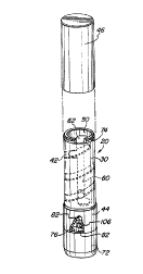
FIG. l is a perspective view of an embodiment of an
innerbody flex tab cosmetic dispenser in accordance with
the invention with a partial cutaway showing one of the
frictional flex tabs of the present invention.
FIG. 2 is an exploded view of the dispenser of FIG.
1.
FIG. 3 is a side elevation view of the dispenser of
FIG. l with partial cutaway.
FIG. 4 is a detail cross sectional view of one of
the flex tabs of the dispenser of FIG. 3 along the line
4-4.
FIG. 5 is a detail side elevation view of a second
embodiment of the flex tab of an embodiment of a
dispenser in accordance with the invention.
FIG. 6 is a detail cross-sectional view of the flex
tab of FIG. 5 along the line 6-6 thereof.
FIG. 7 is a detail cross sectional view of the flex
tab of FIG. 5 along the line 7-7 thereof.
FIG. 8 is a detail side elevation view of a third
embodiment o~ the flex tab of an embodiment of a
dispenser in accordance with the invention.
FIG. 9 is a perspective view of an embodiment of an
2~ .~$3
-- 6
elevator cup of a dispenser in accordance with the
invention.
FIG. 10 is a cross-sectional view of the elevator
cup of FIG. 9.
FIG. 11 is a cross sectional view of the dispenser
of FIG. 3 along line 11-11 showing the flex tabs of the
present invention when the elevator cup is retracted
into the innerbody but not yet locked.
FIG. 12 is a cross sectional view of the dispenser
of FIG. 11 showing the f lex tabs of the present
invention when the elevator cup is retracted into the
innerbody and moved into a locked position.
DETAILED DESCRIPTION OF
THE PREFERRED EMBODIMENT
Referring now to FIGS. 1-12, where like elements
are identified by like numbers in the drawings, an
innerbody f lex tab cosmetic dispenser is shown generally
at 20. Dispenser 20 comprises a cam sleeve 30, an
innerbody 50, and an elevator cup 108.
Cam sleeve 30 is rigid and tubular and has an upper
end 32 and a lower end 34. Cam sleeve 30 has an inner
wall 36 and an outer wall 38. At least one and
preferably two internal helical threads 40 and 42 are
formed on the inner wall 36. ~elical threads 40 and 42
are located 180 degrees apart and extend along a
substantial length of the inner wall 36 of the cam
sleeve 30. Cam sleeve 30 has an unthreaded lower inner
wall segment 44 at its lower end 34. An ornamental outer
shell 46 such as a brass tube may be fitted over the
7 2~JLÇ~3
outer wall 38 of the cam sleeve for decoration.
Innerbody 50 is also tubular and has an upper end
52 and a lower end 54. Innerbody 50 has an inner wall 56
and an outer wall 58. Innerbody 50 is fitted into the
cam sleeve 30 and has at least one and preferably two
longitudinal tracks 60 and 62 which extend along the
axial length of the innerbody 50 and which extend
through the walls 56 and 58 of the innerbody 50 along a
substantial length of the innerbody 50. Preferably, one
of the longitl~i n~l tracks 60 extends to the upper end
52 of the innerbody 50 so that it is open at its upper
end. The other longitn~; n~l track 82 preferably does not
so extend so that it is closed at its upper end.
The longitudinal tracks 60 and 62 have at their
lower ends lower lateral track segments 64 and 66
respectively which preferably extend perpendicularly
from the longitudinal tracks 60 and 62. The longitu~; n~l
tracks 60 and 62 preferably also have at their upper
ends upper lateral track segments 68 and 70 respectively
which preferably also extend perpendicularly from the
longitu~inAl tracks 60 and 62. Preferably, the upper
lateral tracks 68 and 70 extend in the opposite
direction from the lower lateral tracks 64 and 66. The
upper lateral track segments 68 and 70 assist the
elevator cup 108 to be locked in an extPnde~ position
for application of a cosmetic.
The innerbody 50 is interlocked with the cam sleeve
30 so that rotation or application of a swivel torque to
the cam sleeve 30 relative to innerbody 50 can be
accomplished by gripping an exten~eA cylindrical portion
knob 72 on innerbody 50 with one hand and cam sleeve 30
with the other hand to raise or lower elevator cup 108
2~J.~
-- 8
as set forth hereafter. The cam sleeve 30 and innerbody
50 are preferably secured together by a retaining lip 74
on the upper end 52 of innerbody 50 that retains the
upper end 32 of cam sleeve 30 in place on innerbody 50.
5 The knob 72 of innerbody 50 has a larger diameter than
the lower end 34 of cam sleeve 30 and thereby holds the
cam sleeve lower end 34 in place. Alternative retaining
means might also comprise an interfitting comhination of
a rib and channel for receiving the rib.
At least one and preferably two resilient flex tabs
76 are formed with and attached to the innerbody 50
above knob 72. The two flex tabs 76 are located about
180 degree3 apart. The tabs 76 are at least partially
cut away from the innerbody 50 to enhance resllience.
The flex tabs 76 have various embodiments as described
hereafter and each has sufficient resilience to be
flexed radially inwardly.
Referring now to FIGS. 1-4, an embodiment of a flex
tab is shown at 76 and is a horizontal element 78 which
is attached at its two horizontal ends 80 to the
innerbody 50. The flex tab 76 is cutaway from and
separated from the innerbody 50 by spaces 82 located
along the upper edge 84 and lower edge 86 of the
horizontal element. Another PmhoA; ment of the flex tab
is shown in FIGS. 5-7 as 88 and comprises a horizontal
element 90 attached at only one hori~ontal end 92 to the
innerbody 50. Flex tab 88 is therefore cutaway and
separated from the innerbody 50 by spaces 94 located
along three edges of the horizontal element 90. A
further PmhoAimPnt of a flex tab is shown in FIG. 8 as
96 and comprises a vertical element 98 attached at two
vertical ends 100 and 102 to the innerbody 50. Flex tab
96 is therefore cutaway and separated from the innerbody
2 ~ --, L~
_ 9 _
50 by spaces 103 located along lateral edges 104 of the
vertical element 98.
The flex tabs 76, 88 or 96 are preferably provided
with a radially outwardly extending bump 106 to provide
a frictional engagement with the lower inner segment 44
of the cam sleeve 30, whereby the frictional engagement
provides a relatively consistent drag between the bumps
106 and the lower inner segment 44 of the cam sleeve 30
when the innerbody and cam sleeve are rotated relative
to each other. This provides the desired sense or feel
of quality to the consumer user. In addition, the
frictional braking effect min;m;zes undesirable po~P
back-off during use of the dispenser. Such back-off can
otherwise occur when pressure is applied to a cosmetic
pomade during use. Bump 106 preferably has a generally
hemispherical shape with a ~lattened frictional surface.
Referring now to FIGS 1-3 and 9-12, the elevator
cup 108 is generally cylindrical and has a chamber 110
for cont~1ning a cosmetic preparation ~uch as lipstick.
The cup 108 is fitted into the innerbody 50. Cup 108 has
at least one and preferably two cam follower lugs 112
for seating in and following in the longitu~inAl tracks
60 and 62 of the innerbody 50 and the helical threads 40
and 42 of the cam sleeve 30. The lugs 112 are located
180 degrees apart and have a sufficient length to extend
through the longitu~in~l tracks 60 and 62 to engage the
helical threads 40 and 42. The cup 108 has an upper
segment 113 and a lower skirt 114. Located below the
lugs 112 are reduced radius zones 116 in skirt 114. In
the reduce~ radius zones 116 the cup 108 has a lesser
radius than in the upper segment 113. The reduced radius
zones 116 are preferably rectangular flat areas located
below lugs 112.
~ ?~
- 10 --
Cup 108 is movable in an axial path in a con-
ventional manner by relative rotation of the innerbody
50 and cam sleeve 30 by virtue of the lugs 112 seating
in the helical threads 40 and 42 of cam sleeve 30 and
the longitudinal tracks 60 and 62 of innerbody 50. The
relative rotation of the cam sleeve 30 and innerbody 50
causes the cup 108 to move axially to propel the
elevator cup 108 to an extended position, and relative
rotation in the opposite direction causes the elevator
lo cup 108 to retract to a retracted position as shown in
FIG. 3. In the preferred embodiment, the helical threads
40 and 42 are right hand threads in the cam sleeve 30
and have a thread pitch of about 30 degrees so that each
makes one complete revolution as the cup 108 traverses
ls the length of the dispenser 20. This is desirable as
only a single turn is needed to fully activate the
dispenser 20.
The reduced radius zones 116 located below the lugs
112 provide the elevator cup 108 with sufficient
clearance to be retracted into the innerbody 50 to a
limit of longitudinal travel without interference
between the flex tabs 76, 88 or 96 and the elevator cup
108. In particular, the reduced radius zones 116 provide
sufficient clearance for the flex tabs 76, 88 or 96.
Further relative rotation of the innerbody 50 and cam
sleeve 30 causes the elevator cup lugs 112 to track into
the lower lateral track segments 64 and 66, causing the
cup 108 to be rotated until the reduced radius zones 116
are rotated away from the flex tabs 76, 88 or 96. At
this point, the flex tabs 76, 88 or 96 frictionally
engage or confine the elevator cup 108 and hold it in
place. The gripping or confining of the cup 108 by the
flex tabs 76, 88 or 96 is in part caused by the counter
- 1 1 - 2~ ÇJ'~ ~3
pressure of the lower inner segment ~4 of the cam sleeve
30 which presses back against the flex tabs 76, 88 or 96
which are bei~g forced radially outwardly b~ the cup
108.
The secure gripping or confinement of the cup 108
minimizes vibration of the cup in the innerbody and
conseguently reduces the likelihood of damage to a
cosmetic stick 118 installed in cup 108 that could occur
if the stick was subject to impact against the innerbody
inner wall 56 due to the vibration.
In an alternative embodiment, it is possible to
locate the flex tabs on the cam sleeve so that they
extend radially inwardly to bear against the elevator
cup through a properly positioned opening in the
innerbody. In such case it is desirable to have an
outer annular wall provided on the innerbody to wrap
around the cam sleeve and the flex tabs to keep the flex
tabs from escaping radially outwardly. Otherwise the
desired braking and cup securing functions could be
ineffective.
The innerbody 50 and the cam sleeve 30 are
preferably formed by molding from a thermoplastic such
as styrene. The flex tabs are molded into the innerbody
and provide the additional benefit of pierced walls in
the innerbody that correspond to holding ribs in a mold
that help to hold a core pin in an upright and steady
position during the molding process.
Typically, a cap will also be provided with the
dispenser 20. Such a cap has a lower end suited for
fittin~ over the cam sleeve and its decorative shell,
and can be frictionally mounted on the lower end of the
- 12 ~
innerbody 50. For decorative enhancement, the cap and
the lower end of innerbody 50 may also have decorative
shells fitted over them. These decorative shells may be
affixed to their respective underlying structural
5 components by gluing and/or by forming their ends to
clip onto the ends of the cam sleeve, cap and innerbody
lower end.
The present invention therefore provides a new and
useful cosmetic dispenser with an inner body flex tab
suited to grip or confine the elevator cup to prevent
damage to a cosmetic pomade during transport. In
addition, the flex tabs provide a frictional braking
effect that gives the dispenser a desired quality feel
and also prevents pomade backoff during application of
the cosmetic.
It is to be appreciated that the foregoing is
illustrative and not limiting of the invention, and that
various changes and modifications to the preferred
embodiments described above will be apparent to those
skilled in the art. Such changes and modifications can
be made without departing from the spirit and scope of
the present invention, and it is therefore intended that
such changes and modifications be covered by the
following claims.