Note: Descriptions are shown in the official language in which they were submitted.
INDEX 81'7
y
SPECIFICATION
E~771PORATOR OR E~IAPORATOR CONDEI~~ER
10
Field of the Invention
This invention relates to two phase heat
exchangers, and more particularly, to two phase heat
exchangers such as are used in air-conditioning or
refrigeration systems or heat pumps.
BackGround of the Invention
Tn vapor compression, air-conditioning or heat
pump systems, a heat exchanger is disposed in some sort of
an air handling device as a plenum associated with a
blower. Tn the case of air-conditioning systems, most
usually, but not always, the plenum is the hot air plenum
of a furnace.
In any event, in both air-conditioning systems
and in heat pump systems, for cooling purposes this heat
exchanger is employed as an evaporator to evaporate a
2 ~ _
working fluid for the purpose of absorbing heat from
ambient air driven through the heat exchanger by the blower
associated with the plenum. In the case of a heat pump,
this heat exchanger, far heating purpose:, will also serve
as a condenser for the working fluid which ga.ves up heat
to the ambient air upon condensing within the heat
exchanger.
Most frequently, these heat exchangers are in the
form of so-called A-coil evaporators. In the usual case,
an A-coil evaporator is in actuality formed of two
essentially separate heat exchangers that are inclined
upwardly toward each other. Each heat exchanger is made up
of a plurality of plate fins disposed in parallel and in
vertical planes through which horizontally oriented, round
tubes pass. The ends of the round tubes emerging at such
end of the bundle of plate fins are connected by U-tubes.
A double trough which is in effect a trough with ~n open
center mounts the two heat exchangers with the trough on
each side of the central opening receiving condensate from
an associated one of the two heat exchangers, The air to
be cooled or heated passes up the open center of the trough
and thraugh the plate fins in an upward and diagonally
outward direction within the plenum.
While A--coil evaporators have worked well for
their intended purpose, they are not without a number of
drawbacks. For one, in many instances when operating as
evaporators, condensate condensing on the plate fins does
riot drain well and may bridge the gap between adjacent
fins.
The resulting water bridge impedes air flow
through the heat exchanger which in turn reduces heat
transfer from the air. Fin and tube temperature may drop
TI~TI~EX 817
- 3 --
such that the water bridging the fins begins to freeze. As
a consequence, drainage is increasingly impeded and the
entire heat exchanger may ultimately freeze up.
While this difficulty may be solved by employing
a greater air flow, that results in .increased capital
expense in terms of a larger motor and/or blower as well as
increased operating costs,
Furthermore, manifolding the two heat ezcchangers
together into an A-coil heat exchanger requires the
l0 performance of a significant number of purely manual
operations, thus increasing manufacturing costs. In
addition, because each tube has two soldered or brazed
joints, one at each end, there is a relatively large
potential for refrigerant leakage where a large number of
tubes are employed. Conventional A-coils are also heavy
and frequently difficult to handle during installation as
a result. They axe also easily damaged.
In many instances, proper distribution of the
refrigerant through the heat exchanger when used as an
2o evaporator may require fairly complex plumbing and/or a
complex distribution system to achieve a desired degree of
temperature uniformity of exiting air across the heat
exchanger.
Moreover, when a heat exchanger is employed in a
heat pump system, and thus must function as both an
evaporator and a condenser; efficiencies are of substantial
concern. Two phase heat exchange operations as when one
heat exchange fluid is transitioning from the liquid phase
to the vapor phase or vice versa are nowhere near as well
understood as single phase heat exchange operations.
Furthermore, in differing two phase heat exchange
operations, what may be of concern in one is not of concern
INI7~X 817
in the other. For example, in the two phase heat exchange
operation of evaporation within a refrigeration system,
provision must be made to dispose of conclensate resulting
from moisture in ambient air being passed through the heat
exchanger condensing on the cool surfaces thereof. There
is no corresponding air side problem in the two phase
operation of condensation. However, in the two phase
operation of condensation on the refrigerant side,
gravitational effects may dictate the orientation of
various passages because it is difficult to cause
condensate to flow uphill when mixed with substantially
less dense vapor. In heat exchangers operating as
evaporators, orientation for gravitational purposes may not
be as critical.
On the other hand, if incoming refrigerant in a
heat exchanger operating as an evaporator is not uniformly
distributed, substantial temperature differentials in air
exiting different parts of the evaporator may occur and
heat exchange efficiency suffers. distribution of incoming
vapor is not, however, a great concern in a heat exchanger
operating as a condenser.
Consee~uently, there is not only a real need for
a new and improved evaporator, there is also a need for a
heat exchanger that can alternatively function with great
efficiency as both an evaporator and as a condenser so as
to be especially adapted for use in a heat pump system.
Summary of the Invention
It is a principal object of the invention to
provide a new and improved evaporator or
evaporator/condenser for use in a refrigeration or heat
pump system. More specifically, it is an object of the
IrrDEx sly
-
invention to provide such an evaporator or
evaporator/condenser that is relatively inexpensive to
manufacture, that is relatively lightweight and nc~t
susceptible to damage; that provides excellent drainage of
condensate when operating as an evaporator: which requires
a small condensate collection trough and which requires a
reduced charge of refrigerant over conventional A-coil
evaporators or evaporator/condensers.
It is also a principal object of the invention to
provide a method of manufacturing such an evaporator or
evaporator/condenser.
An exemplary embodiment of the invention achieves
one of the foregoing objects in an evaporator or
evaporator/condenser construction includ~.ng first and
second, spaced, pressure resistant headers. A plurality of
elongated tubes of flattened cross-section extend in
parallel, spaced relation between and in fluid
communication with the headers. Serpentine fins extend
between and are bonded to adjacent one pair of the tubes.
The tubes and the fins, between the headers, are configured
to define a non-planar configuration having an apex.
In a preferred embodiment, the headers define a
plane and the apex extends downwardly away from the plane,
to thereby provide a U or V-shaped conf~.guratian.
A preferred embodiment contemplates the provision
of a condensate trough aligned with and below the apex and
mauwted thereto.
In a highly preferred embodiment, the tubes are
farmed of extruded aluminum and include plural internal
webs dividing each tube into plural flow passages of
relatively small hydraulic diameter.
zz~D~~ 817
- 6 - , 2~~:~6~
zt is also highly preferred, particularly when
the device is an evaporator/condenser, that the hydraulic
diameter be 0.070 inches or less, even more preferably,
the hydraulic diameter is 0.040 inches o~: less.
The invention contemplates that the tubes have
major and minor dimensions and that the apex is defined by
bends in the tubes resulting from bending forces applied
across the major dimensions of the tubes.
Typically, the tubes and fins define a core. The
invention contemplates that side pieces be located on
opposed sides of the core and extend between the headers.
The side pieces are elongated and include accordion
formations intermediate their ends to facilitate the
formation of the apex. In a highly preferred emb~diment,
the accordion formatipns include slots extending
transversely partially across the respective side pieces in
the vicinity of the apex. In a highly preferred
embodiment, each side piece includes opposed edges and the
slots are located in both of the edges with the slot in one
edge being staggered with respect to the slots in the other
edge.
The invention also includes the provision of a
baffle in at least one of the headers intermediate the ends
thereof to thereby define a multiple pass evaporator or
evaporator/condenser. In a highly preferred embodiment,
there is but a single baffle in one of the headers at the
approximate mid-point thereof so that there are two passes
of approximately equal flow area,
The invention also contemplates the provision of
a multiple tube row evaporator or evaporator/condenser.
This aspect of the invention is defined by a nested
configuration of at least two of the evaporators or
IND~~ 81?
? - ~~~~.~9~
evaporator/condensers described previously which are
secured together.
In one eznbodimewt of the invention, the multiple
tube row evaporator or evaparator/condenser Yeas the tubes
in adjacent rows aligned with one another. Tn another
embodiment, the tubes in adjacent taws axe staggered with
respect to each other.
Tn a highly preferred embadimen~t:, the serpentine
fins and the tubes are formed of aluminum. Preferably,
l0 there are at least about twenty fins per inch.
According to another aspect of the invention,
there is provided a method of making an evaporator or
evaporator/condenser which includes the steps of, a~
assexabling parallel flattened tubes to spaced parallel
15 headers with serpentine fins between the tubes; b)
subjecting the assemblage resulting from step a) to a
banding process to unite the headers, the 'tubes and the
fins into a unitary assembly; and, c) thereafter bending
the unitary assembly between the headers into a U or V
20 shaped configuration.
Preferably, the fins, the tubes and the headers
are aluminum and the bonding process of step b) is a
brazing process.
The invention contemplates that the bending step
2~ be followed by the step of adding side panels and attaching
a trough to the unitary assembly so as to align with and
open toward the bottom of the U or V-shaped configuration
and thus act as a condensate collection trough.
The invention further contemplates that step a)
30 include the application of side pieces to opposed sides of
the assemblage so as to flank the same and extend between
INDE?~ 817
8 °
the headers arid that the side pieces are provided with
accordion formations intermediate their ends,
In one embodiment of the invention, steps a), b)
arid c) mentioned previously are repeated to provide at
least two U or V-shaped configurations and are followed by
the step of d) nesting the U or V-shaped configurations in
a stack to provide a multiple row evaporator or
evaporator/condenser.
This embodiment of the invention further
contemplates the additional step of e) attaching a trough
to the evaporator or evaporator/condensex~ below the lower
most U or V-shaped configuration in alignment with the
bottom thereof and opening toward the U or V-shaped
configuration.
In this embodiment of the invention, one form
contemplates that the step of nesting include aligning the
tubes in adjacent U ar V-shaped configurations while
another form of the invention contemplates that the nesting
step include staggering the tubes in adjacent U or V-shaped
configurations,
The method of the invention also contemplates a
step of forming a baffle in one of the headers intermediate
the ends thereof to thereby provide a multiple pass
evaporator or evaporator/condenser.
f5ther objects and advantages will become apparent
from the following spacificatian taken in connection with
the accompanying drawings.
Description of the Drawincxs
Fig, l is an exploded view of a heat exchanger. of
the so-called parallel flow type and illustrating a number
xrrnEx ale
~~~C3~
of the important components of an evaporator or
evaporator/condenser made according to the invention;
Fig. 2 is an enlarged, sectional view of an
extruded, flattened tube employed in the invention;
Fig. 3 is a plan view of an evaporator or
evaporatar/condenser made according to the invention prior
to complete formation;
Fig. 4 is a side elevation of t:he evaporator or
evaporator/condenser at the same stage of manufacture as
illustrated in Fig. 3.
Fig. 5 is a view similar to FicJ. 4, but showing
the evaporator or evaporator/condenser at a subsequent
stage in the manufacture thereof;
Fig. 6 is a side elevation of a finished
evaporator/condenser;
Fig. 7 is a perspective view of the finished
evaporator/condenser;
Fig. 8 is a fragmentary, elevational view of the
evaporator or evaporator/condenser taken from the right of
Fig. 6;
Fig. 9 is a schematic of a core folding
apparatus;
Fig. 10 is a view similar to Fig. 5, but of a
multiple tube row embodiment of the invention;
Fig. 11 is an enlarged, fragmentary sectional
view of one tube alignment of a multiple tube row
embodiment of the invention; and
Fig. l2 is a view similar to Fig. 11, but of
another embodiment of the invention.
_.....,~
INDEX 817
- 10
~0~~.9~
Description of the Preferred Embodiments
A heat exchanger of the parallel flow type is
illustrated in Fig. 1. Tt is to be understood that Fig. 1
does not illustrate a finished evaporator or
evaporator/condenser made according to the invention, but
does illustrate a heat exchanger having a very high degree
of identity with the evaporator or evaporator/condenser of
the invention. Tt is included mare by way of providing
ready reference and explanation for the description of
actual embodiments made according to the invention than for
any other purpose.
As seen in Fig. 1, the heat exchanger includes
opposed, spaced, generally parallel headers 10 and 12. The
headers 10 and 12 are preferably made up from generally
cylindrical, aluminum tubing having aluminum braze cladding
on its exterior surface. On their facing sides, they are
provided with a series of generally parallel slots or
openings 1~1 for the receipt of corresponding ands l& and l.8
of flattened tubes 20. The tubas 20 are preferably formed
of aluminum extrusions as will be described in greatez~
detail in connection with Fig. 2 herein.
The header tubes l0 and 12 are preferably welded
and thus include a weld seam shown at 1~ on the header 12.
The slots 14 are punched in the sides of the headers 10 and
1.2.
Preferably, between the slots 14, in the area
shown ~t 22, each of the headers l0 and 12 is provided with
somewhat spherical domes to improve resistance to high
pressure as more fully disclosed in commonly assigned
Saperstein, et al. U.S. Patent 4,615,385,
fl$~ flfl~
TrrD~x ale
- 11 -
The header 10 has opposite ends closed by caps 2~
brazed or welded thereto. Tn the preferred embodiment of
the invention, the various camponents are all brazed
together and accordingly, in the usual case, brazing will
be the means employed to fasten the caps 24 to the header
10. Similarly, fittings such as a vapor inlet/outlet
fitting 26 may be brazed to one end of the header 12 whale
a liquid inlet/outlet fitting 32 may be brazed to the
opposite end thereof. Because inlet and outlet flow must
be separated, the header 12 is slotted intermediate its
ends as at 33, and specifically, at its midpoint to receive
a baffle 35. AcCOrding to the invention, the slot 33 and
baffle 35 are formed according to commonly assigned U.S.
Patent No. 4,936,381 to Alley.
As can be readily seen in Fig. l, a plurality of
the tubes 20 extend between the headers 10 and 12 in
parallel relationship and in fluid communication with the
interior of the headers to and l2. the tubes 20 on one
side of the baffle 35 are thus hydraulically in parallel
with one another while the tubes on the opposite side of
the baffle 35 are in hydraulic parallel with one another,
but in series with the first group of tubes, thus forming
a two pass heat exchanger.
Aisposed between adjacent ones of the tubes 20
are louvered serpentine fins 34 of braze clad aluminum.
According to the invention, there are preferably at least
twenty and as many as twenty-six fins per ~.nch. Upper and
lower aluminum side pieces 36 and 38 extend between the
headers 10 and 12 to provide rigidity to the system.
As seen in Fig. 2, each of the tubes 20 is an
extruded flattened tube haying a minor dimension and a
TNDEX 8 ~ ~_ ~'
- 12 -
major dimension. Typically, the miner dimension is made as
small as possible since this dimension faces the direction
of air flaw through the heat exchanger. As a consequence,
for a given frontal area of a heat exchanger, an increase
in the minor dimension will reduce the air flow area and
thus increase pressure drop across the heat exchanger,
requiring more energy to pass air through the same.
Furthermore, an increase in the minor dimension of the tube
20 will also decrease the area available for air side
l0 surface enhancement as is typically provided by fins such
as the fins 34.
At the same time, the minor dimension cannot be
made too small or else it may result in the internal
passage or passages within the tube 20 being so reduced in
. size as to be overly resistant to the flow of the heat
exchange fluid flowing within the tubes.
In a typical case, the minor dimension might be
on the order of 1.90 mm.
In the embodiment illustrated in Fig. 2, the
major dimension of the tube 20 is slightly greater than an
inch at 27.56 mm. This dimension is chosen in connection
with the tube minor dimension to provide the desired flaw
aria through each tube. As will become apparent from the
following description, some care must be exercised in
selecting the tube major dimension so that i~t is not so
large as to result in buckling when a bending force is
applied across the tube major dimension. Generally, the
tube major dimension will be in the range of about l3 mm to
32 mm.
Within each flattened tube 20 are a plurality of
flow passages 40 of generally triangular configuration.
The flow passages 40 are separated by integral webs 42
IN'DHX 817
° 13 -
extending between the sides of the tube 20. In the usual
case, the interior tuba walls 44 and 46 along with the webs
42 will define the passages 40 so they have a relatively
small hydraulic diameter. Hydraulic diameter is as
conventionally defined, namely, the cross-sectional area of
a given flow path multiplied by four and in turn divided by
the wetted perimeter of the corresponding flow path.
According to the invention, it is preferred that the
hydraulic diameter be in the range of about 0.015 to about
to 0.070 incries (0.381 - 1.78 mm) and preferably, 0.04 inches
(1.02 mm) or less. In the embodiment illustrated, the
hydraulic diameter is 0.031 inches (0.79 mm). These
hydraulic diameters provide for high efficiency operation
as a condenser independent of the orientation of the tubes
20 by eliminating the effect of gravity as more fully
pointed out in commonly assigned U.S. Patent 4,998,580 to
Guntly, et al..
The webs 42 provide a number of functians. In
addition to serving with the inner walls 44 and 46 of each
tube 20 to define the individual and discrete flow paths 40
that extend from one end of the tubes 20 to the other, they
serve to strengthen the tubes 20 against buckling of one
side wall toward or away from the other when a bending
force is applied across the tube major dimension.
They also serve to prevent rupture of the tubes
20 when subjected to relatively high internal pressures.-
Finally, in heat transfer itself, hes.t may flow to or from
the webs 42 from or to the side walls of the tubes 20. The
fluid within the tubes 20 will, of course, be in contact
with the webs 42 and thus in heat exchange relation
therewith. Thus, that part of the fluid within the tubes
INDEX 817~~~~~~~
14 s~
20 not in contacts with the surfaces 44 and 46, bu°~ in
contact with the webs 42 is still. subject to goad heat
transfer to or from the corresponding tube 20 itself via
the webs 42.
~f course, when the heat exchanger is being used
as an evaporator, the flow of heat will be from the fins 34
to the tubes 20 to the refrigerant flowing within the
passages 40. If the heat exchanger is used as an
evaporator/condenser in a heat pump system, when used as an
evaporator, heat flow will be as just mentioned. However,
when used as a condenser in a heat pump system, heat flow
will be from the refrigerant contained within the passages
40 to the tube 20 and then to the serpentine fins 34 (Fig.
1) .
Turning now to Figs. 3 and 4, scale showings of
an evaporator or evaporator/condenser made according to the
invention are illustrated. It will be appreciated that the
length of the tubes 20 as illustrated in Fig. 3 is much
greater than that illustrated in Fig. 1 and this is in
accordance with the invention. The purpose of the
increased length is to allow a planar heat exchanger like
that illustrated in Fig. 1 to be bent intermediate its ends
to form a U or a V--shaped configuration having two spaced
legs, each in turn having a size roughly egual to the heat
exchanger illustrated in Fig. 1, although obviously this
will vary dependent upon the par°ticular system in which the
heat exchanger is to be included.
In any event, in Fig. 3, like reference numerals
are utilized to .illustrate like parts. It will be seen
that a baffle 35 is disposed within the header 10 at the
approximate midpoint thereof. As a consequence, the number
of tubes 20 on each side of the baffle 35 will be
INDEX 817
15 -
substantially the same. Where all tubes 20 are identical,
the baffle 35 in the header 10 creates two passes of
substantially equal cross-section or flow area. Through
the use of additional baffles 35, additional passes may be
created if desired. A relatively large diameter tube 50,
is in fluid communication with that part of the header 10
below the baffle 35 and serves as a vapor' outlet tube when
the heat exchanger is operating as an evaporator. or as a
vapor inlet tube when the heat exchanger is being used as
a condenser in a heat pump system.
A smaller diameter, liquid inlet/outlet tube 52
is in fluid communication with the interior to the header
10 an the upger side of the baffle 35.
In many instances the sides of the evaporator are
closed off by V or U-shaped imperfarate side panels 53
(Figs. 6 and 7) mounted to the side pieces 36 and 38. The
imperforate side panels 53 prevent air from flowing from
one side of the core to the other around the side pieces
36, 38 without passing through the fins 34.
At the upper sides of the side panels 53 as well
as at the headers 10, 12 a peripheral mounting flange 54 is
looted. The flange 54 has a flat horizontal peripheral
seat 55 which is adapted to rest on and be sealed to an
appropriate seat within a plenum of a furnace, air handler
or heat pump with which the evaporator/condenser is to be
used. Thus, the side panel and the seat 55 serve to force
air flow through the core and prevent bypassing of the
same.
The header 12 is desirably provided with a jumper
tube 56 which interconnects those sections of the header 12
on opposite sides of the baffle 35 in that header, but
INDEX 81?
- 16 -
which is not absolutely required and may be omitted along
with the baffle 35 in some instances.
It will be noted from Fig. 3 that the tubes 50,
52 and 56 all connect into the approximate center of the
section of the header 10 or 12 with which they are
associated. This feature of the invention is most
important when the heat exchanger is operating as an
evaporator since a.t provides good di~~tribution of the
refrigerant throughout the evaporator to minimize
temperature differentials from one part of the heat
exchanger face to another.
Turning now to Fig. 4, the side piece 38, at its
approximately midpoint is provided with an accordion
formation, generally designated 60. The side piece 36 is
similarly provided with such an accordion formation (not
shown) at the same location.
Each accordion formation is defined by a series
of slots or notches. As seen in Fig. 4, one edge 62 of the
side piece 38 is provided with a series of slots or notches
64 that extend transversely to the direction of elongation
of the side piece and toward the opposite edge 66, but not
completely thereto. Similarly, the edge 66 is provided
with a series of slightly longer slots or notches 68 which
extend toward the edge 62. The slots 64 have a depth of
approximately two-thirds the depth of the slots 68 and a
continuous center area 70 expending along the length of the
side piece 38 between the bottoms of the slots 64 and 68
may have a width that is approximately the same as the
depths of the slots 64 or possibly slightly less.
The heat exchanger as shown in Figs. 3 and 4 is
assembled generally according to the process disclosed in
commonly assigned United States hettex°s Patent 4,688,311 to
i
IND~x 817
- 17 -
Saperstein.
Its structure at this point in i.ts manufacture
is, other than length of the tubes 20, essentially as
disclosed in commonly assigned U.S. Pa~:ent 4,998,580
previously identified. However, it is preferred to use
extruded tubes such as that illustrated in Fig. 2 herein to
tubes provided with spacers. or inserts as specifically
disclosed in Patent 4,688,311. or Patent 4,998,580. Where
the latter are used, they will be fabricated of braze clad
l0 aluminum, and the fins 34 need not be braze clad in this
case.
It will be appreciated that the heat exchanger
illustrated in Figs. 3 and 4 is, of course, planar.
According to the invention, it is desired that the heat
exchanger be made into a U or V-shaped configuration such
as illustrated in Fig. 5. To this end, the heat exchanger
of Figs. 3 and 4 is bent to the configuration shown in Fig.
5. The bend occurs in the area of the accordion formations
60. The bend may be formed with an apparatus like that
shown in Fig. 9. The heat exchanger in a planar form as in
Figs. 3 and 4 has one end abutted to the underside 71 of
a bench 72 and extends such that its midpoint with the
accordion formations 6Q is disposed on a fixed, cylindrical
mandrel 73 mounted to the bench by inverted L-shaped arms
74. The mandrel 73 will typically have a diameter of 4
inches or more.
A handle 75 is pivoted to the mandrel 73 at its
cylindrical axis and, intermediate its ends, carries a
roller 77. A plate 78 may be loosely disposed on the upper
surface of that part of the heat exchanger extending past
the mandrel and in turn is engaged by the roller 77. By
swinging the handle 75 in the direction of an arrow 79, the
INDEX g17
- 18 -
requisite bending force is uniformly applied through the
plate 78 until the configuratton shown in Fig. 5 is
obtained.
This bending force is, of course, being applied
across the major dimension of the tubes 20, but the same,
being aluminum extrusions, readily deform without buckling.
Tubes having individual inserts as described in the
previously identified U.S. Patent 4,688,311 may also be
utilized in lieu of extrusions, but for a comparable major
dimension the same have a greater tendency to buckle during
the bending process. The accordion formation 60 allow the
side pieces 36 and 38 to bend without appreciable buckling.
In any event, the bend results in the formation
of an apex 80 at the approximate midpaint of the. accordion
formation 60. The apex 80 is below the plane defined by
the headers 10 and 12. To this apex 80, a condensate
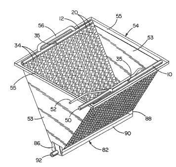
trough, (Figs. 6 - 8) generally designated 82, is attached
as by screws 84 extending into the side panels and possibly
the side pieces 36 and 38 as well. The trough 82 is formed
of end pieces 86 and 88 and a connecting U-shaped, upwardly
opening bottom and side wall piece 90. The endwall 86 ox
the endwall 88, or both, may be provided with one or mare
condensate outlet fittings 92.
As can be appreciated from Fig. 8, the minor
dimensions of the tubes 20 are all exposed and free from
the serpentine fins 34 which extend along only major
dimensions of the tubes between adjacent tubes or, at the
sides of the resulting core, between a 'tube 20 and one of
the side pieces 36 and 38. As a consequence, condensate
farming on the fins 34 or tubes 20 and flowing to one of
'the tubes 20 is free to run down the same in the space
between adjacent fins 34 until the apex 80 is reached.
INDEX 817
19 - _
Same o.f the condensate will also pass through the cost~mary
louvers in the fins 34 and descend to the apex 80. As 'the
condensate builds up at the apex 80, droplets of sufficient
size to overcome the surface tension forces attaching the
condensate to the apex 80 will be created and the
condensate will then drop free into the condensate
collection trough 82.
Through the use of a U or a V-shaped
configuration, a single condensate collection trough such
as the trough 82 is advantageously employed in contrast to
the requirement for two separate collection areas or
troughs found in typical A-coil evaporator installations.
The invention also contemplates the provision of
a multiple tube row evaporator or evaporator/condenser. A
two tube row evaporator or evaporator/condenser is
illustrated in Fig. l0. Basically, two or moxe of the
cores without the trough 82 as illustrated in Fig. 5, and
with appropriate parts of the ,inlet, outlets arid other
connecting tubing omitted, are simply nested as illustrated
in Fig. 10. As illustrated' the uppermost core is labeled
"pore 1" while the lowermost core is labeled "core X" where
X is an integer equal to the total number of cores in °~he
multiple tube row evaporator or evaporator/condenser.
Conduits shown schematically at 100 and 102
interconnect the headers l0 and 12 in any desired flow path
arrangement and the apex 80 of the first core is vertically
aligned with and above the apex 80 of the lowermost core
shown at 80-X in Fig. 10. One of the condensate troughs 82
is connected to the lowermost core, core-X, at its apex 80-
X in the same fashion described previously in connection
with. Figs. 6 - 8. The side panels may be enlarged to span
the distance between cares and then be joined to each core
INDEX 817
~_
2 0 °-
in the stack by screws. Additionally, the conduit
connections 100 and 102 as well as the relative
interference occurring as a result of the nesting of the
cores are employed to secure the same together.
The inlet and outlet tubes 50 and 52 may be
associated with the first core, core 1, .as illustrated in
Fig. 10 or any other cores as desired.
It will be readily appreciated that in an upflow
furnace, air moving through the assemblage of Fig. 10 will
l0 pass through the tubes and fins of each of the cores, core
1 through core X, beginning with the lowermost core, core
X. For a downflow furnace, flow will be in the e~pposite
direction.
Fig. 11 shows one embodiment of a multiple tube
row evaporator or evaporator/condenser made according to
the invention, specifically a three 'tube row evaporator or
evaporator/condenser. The serpentine f~.ns are shown at 34
and are seen to include enhancements such as conventional
louvers 110. The flattened tubes are again shown at 20 and
it will be observed that the tubes 20 in adjacent cores are
staggered. Such an arrangement can be achieved by
appropriately locating the slots 14 (Fig. lj in the headers
ZO and 12 using one set of locations for core 1 and core X
as viewed in Fig. 11 and another set of locations for core
2. .'alternatively, identical cores could be used with one
shifted slightly with respect to another in the nesting
process so as to achieve the desired stagger.
Alternatively, the tubes 20 on adjacent cores may
be aligned and such an arrangement is illustrated in Fig.
12.
From the foregoing, it will be seen that an
evaporator or evaparator/condenser made according to the
INDF~ 817
2Z
invention can be constructed with a great deal of
flexibility, allowing the same to be readily customized for
any given installation or system. Multiple passes are
easily achieved through the use of baffles while multiple
tube row configurations are easily achieved by nesting
several single row evaporator or evaporator/condenser
constructions.
While each tube has two joints, one at each end
to the adjacent header, which are potential leakage sites,
l0 in some instances, the number of tubes is substantially
reduced from the number of tubes employed in conventional
plate fin round tube A~coil constructions thereby reducing
leakage potential. Significantly, an evaporator or
evaporator/condenser made according to the invention
generally reduces the necessary refrigerant charge in a
typical system in the range of 1.0 ~ 15 percent over an
otherwise equivalent conventional system. Reduction in
refrigerant charge, particularly where the refrigerant is
a CFC or HCFC is highly desirable in that it reduces
potential leakage o~ passibly polluting or otherwise
damaging refrigerants into the environment.
The relatively long length of the tubes 20 of the
structure illustrated in Fig. 5, for example, as contrasted
to the similar heat exchanger as illustrated in Fig. l,
tends to create sufficient resistance to refrigerant flow
that the prpblems of distribution of refrigerant in an
evaporator are reduced. And when the various fluid
connections are generally as illustrated in Fig. 3 in
relation to baffles or the like, distribution problems are
rendered relatively insignificant.
~n the cooling mode, water vapor often condenses
onto the fins and tubes, thereby increasing resa.stance to
INT~EX 817
22 _
air flow. No such condensation tapes place in the heating
mode. As a result, the air side pressure drop in the
cooling mode is always greater than or equal to the air
side pressure drop in the heating mode. The difference
between the cooling mode and heating mode air side pressure
drops is a measure of an evaporator/condenser°s ability to
drain condenaetsv The smaller the difference, the better
the drainage. Zn a conventional plate fin round tube
evaporator/condenser of a particular sire, the heating mode
air pressure drop was determined to be 0.14 inches of
water, while in the coping mode the air pressure drop
across the same was 0.20 inches of water. 2n a similar
capacity evaporator/condenser made according to t3ae
invention, the heating mode air pressure drop was 0.14
inches of water, while the cooling mode air pressure drop
was 0.15 inches of water. This smaller difference in air
pressure drop between the heating and cooling modes
indicates, at the very least, better drainage of condensate
in the evaporator/condenser of the invention over the
conventional plate fin round tube evaporator/candenser
which, of course, is an advantage for the reasons
previously stated.
An ee~aporator or evaporator/condenser made
according to the invention weighs only about oneahalf as
much as a conventional plats fin round tube evaporator of
identical heat exchange capacity, thereby providing a
weight advantage which is of substantial assistance during
an installation procedure.
Furthermore, many of the manual operations
associated with the manufacture of plate fin round tube
evaporators are eliminated, thereby simplifying
manufacture. Additionally, much of the equipment employed
INDEX 817
- 23 -
in manufacturing an evaporator or evaporator/condenser made
according to the invention may be advantageously employed
in manufacturing ether heat exchangers such as that
illustrated in Fig. 1 which is useful as a condenser or as
an oil Gaoler. Thus, oapital reesuirements can be reduced.
Finally, and significantly, the heat exchanger of
the present invention can perform two different heat
exchange operations with a great deal of efficiency,
namely, evaporation and condensation. Thus, the same is
ZO ideally suited for incorporation into heat pump systems to
improve the efficiency thereof.