Language selection

Search

Patent 2081988 Summary

Third-party information liability

Some of the information on this Web page has been provided by external sources. The Government of Canada is not responsible for the accuracy, reliability or currency of the information supplied by external sources. Users wishing to rely upon this information should consult directly with the source of the information. Content provided by external sources is not subject to official languages, privacy and accessibility requirements.

Claims and Abstract availability

Any discrepancies in the text and image of the Claims and Abstract are due to differing posting times. Text of the Claims and Abstract are posted:

  • At the time the application is open to public inspection;
  • At the time of issue of the patent (grant).
(12) Patent: (11) CA 2081988
(54) English Title: SLIDE FASTENER
(54) French Title: FERMETURE-ECLAIR
Status: Expired and beyond the Period of Reversal
Bibliographic Data
(51) International Patent Classification (IPC):
  • A44B 19/00 (2006.01)
  • A44B 19/34 (2006.01)
(72) Inventors :
  • AKASHI, SHUNJI (Japan)
  • KUSAYAMA, MASAHIRO (Japan)
  • YONEZAWA, TSUTOMU (Japan)
(73) Owners :
  • YKK CORPORATION
(71) Applicants :
  • YKK CORPORATION (Japan)
(74) Agent: GOWLING WLG (CANADA) LLP
(74) Associate agent:
(45) Issued: 1996-07-02
(22) Filed Date: 1992-11-03
(41) Open to Public Inspection: 1993-05-06
Examination requested: 1992-11-03
Availability of licence: N/A
Dedicated to the Public: N/A
(25) Language of filing: English

Patent Cooperation Treaty (PCT): No

(30) Application Priority Data:
Application No. Country/Territory Date
3-318328 (Japan) 1991-11-05

Abstracts

English Abstract


A slide fastener comprising: a pair of woven or
knitted stringer tapes having a pair of core threads
extending in and along their confronting inner longi-
tudinal edges; a pair of rows of die-cast coupling
elements mounted on and along the confronting inner
longitudinal edges; and each of said stringer tapes
including a conductive wire extending along the
respective core thread on its side toward the inner
longitudinal edge, an edge warp yarn extending along
the inner longitudinal edge, and a weft yarn having a
succession of turnover portions arranged along the in-
ner longitudinal edge, said conductive wire together
with said edge warp yarn being incorporated into each
said stringer tapes by said turnovers in such a manner
that said conductive wire is partially concealed with
said edge warp yarn and said turnover portions.


Claims

Note: Claims are shown in the official language in which they were submitted.

CLAIMS
1. A slide fastener comprising: a pair of woven or knitted stringer
tapes each having a core thread extending in and along confronting inner
longitudinal edges thereof; a row of die-cast coupling elements mounted on
and along the confronting inner longitudinal edges; and each of said stringer
tapes including a conductive wire extending along the respective core thread
on its side toward the inner longitudinal edge an edge warp yarn extending
along the inner longitudinal edge and a weft yarn having a succession of
turnover portions arranged along the inner longitudinal edge said conductive
wire together with said edge warp yarn being incorporated into each of said
stringer tapes by said turnovers in such a manner that said conductive wire is
partially concealed by said edge warp yarn and said turnover portions.
2. A slide fastener according to claim 1, wherein each of said
stringer tapes comprises an additional conductive wire extending along the core
thread, said succession of turnover portions of said weft yarn arranged to
incorporate said additional conductive wire into said stringer tape.
3. A slide fastener according to claim 1, wherein each of said
stringer tapes comprises an additional core thread extending in and along the
confronting inner longitudinal edges on a side of each said stringer tapes
opposite one of said core threads, and an additional conductive wire extending
along the respective additional core thread on its side toward the inner
longitudinal edge, said succession of turnover portions of said weft yarn
arranged to incorporate said additional conductive wire into said stringer tape.
4. A slide fastener according to claim 1, wherein each of said
stringer tapes comprises an additional core thread extending in and along the
confronting inner longitudinal edges of a side of each said stringer tapes
opposite one of said core threads, and an additional conductive wire extending
along the respective additional core thread on its side toward the inner
longitudinal core thread on its side toward the inner longitudinal edge, and an
additional edge warp yarn extending along the inner longitudinal edge, said
succession of turnover portions of said weft yarn arranged to incorporate said
additional warp yarn and said additional conductive wire into said stringer tape.

5. A slide fastener comprising: a pair of woven or knitted stringer
tapes each having a core thread extending in and along their confronting inner
longitudinal edges; a row of die-cast coupling elements mounted on and along
the confronting inner longitudinal edges; and each of said stringer tapes
including a conductive wire extending along the respective core thread, an
edge warp yarn extending along the inner longitudinal edge, and a weft yarn
having a succession of turnover portions arranged along the inner longitudinal
edge, said conductive wire together with said edge warp yarn being
incorporated into each of said stringer tapes by said turnovers in such a
manner that said conductive wire is partially concealed by said edge warp yarn
and said turnover portions.
6. A slide fastener according to claim 5, wherein each of said
stringer tapes comprises an additional conductive wire extending along the core
thread, said succession of turnover portions of said weft yarn arranged to
incorporate said additional conductive wire into said stringer tape.
7. A slide fastener according to claim 5, wherein each of said
stringer tapes comprises an additional core thread extending in and along the
confronting inner longitudinal edges on a side of each said stringer tapes
opposite one of said core threads, and an additional conductive wire extending
along the respective additional core thread, said succession of turnover
portions of said weft yarn arranged to incorporate said additional conductive
wire into said stringer tape.
8. A slide fastener according to claim 5, wherein each of said
stringer tapes comprises an additional core thread extending in and along the
confronting inner longitudinal edges on a side of each said stringer tapes
opposite one of said core threads, and an additional conductive wire extending
along the respective additional core thread, and an additional edge warp yarn
extending along the inner longitudinal edge, said succession of turnover
portions of said weft yarn arranged to incorporate said additional warp yarn
and said additional conductive wire into said stringer tapes.

Description

Note: Descriptions are shown in the official language in which they were submitted.


- 2081988
SLIDE FASTENER
BACKGROUND OF THE INVENTION
1. Field of the ~nvention:
This invention relates to a slide fastener hav-
ing die-cast coupling elements treated by an elec-
trochemical surface treatment such as electrolyte
plating or electrodeposition painting.
2. Description of the Related Art:
In the manufacture of slide fasteners, it is
currently known to treat a plurality of metal coupling
elements with electrochemical surface treatment such
as electrotytic plating or electrodeposition painting,
after the coupling elements are mounted on a pair of
stringer tapes at regular distances along their con-
fronting inner longitudinal edges. In this case, the
electrochemical surface treatment is done while an
eiectric current is conducted to the individual coup-
ling elements; for this purpose, a conductive wire is
incorporated in the inner longitudinal tape edge on
which the successive coupling elements are mounted.
This prior art is exemplified by Japanese Utili-
ty Model Publications Nos. SHO 39-8208 and SHO 59-7136
and U.S. Pat. No. 2264324 (Cl. 204-23), in which the
conductive wire is situated alongside a core thread
extending along the inner longitudinal tape edge or is
-- 1 -- *

2081988
-
wound around such a core thread. According to these
prior art publications, the conductive wire is at-
tached to the outside edge of the core thread,
projecting from the peripheral surface of the core
thread.
In the case where the metallic coupling elements
are die-cas-t, the stringer tape is held between upper
and lower mold halves, and then molten metal is intro-
duced into the mold to form a plurality of coupling
elements on the stringer tape at equal distances along
the inner longitudinal edge. The upper and lower mold
halves have grooves extending between the individual
cavities for forming the coupling elements; the
grooves serves to receive the inner longitudinal edge
of the stringer tape during die-casting. The contour
of the grooves must be such that the conductive wire
bites into the core thread so as not to project from
the grooves. With the conductive wire projecting from
the grooves, the upper and lower mold halves cannot be
brought into intimate contact with each other. In the
foregoing prior art, however, the projected portion of
the conductive wire would be caught between the groove
edges of the upper and lower mold halves and hence
would possibly be cut off so that electrolytic plating
will be impossible. Since the conductive wire is ex-
posed along the entire length of the core thread, thus

2081988
-
impairing the appearance of the slide fastener as a
finished product.
SUMMARY OF THE INVENTION
it is therefore an object of this invention to
provide a slide fastener in which a conductive wire
can be received within grooves of upper and lower mold
halves reliably without being caught between the
groove edges.
According to the invention, there is provided a
slide fastener comprising: a pair of woven or knitted
stringer tapes having a pair of core threads extending
in and along their confronting inner longitudinal
edges; a pair of rows of die-cast coupling elements
mounted on and along the confronting inner longi-
tudinal edges; and each of the stringer tapes includ-
ing a conductive wire extending along the respective
core thread on its side toward the inner longitudinal
edge, an edge warp yarn extending along the inner lon-
gitudinal edge, and a weft yarn having a succession of
turnover portions arranged along the inner longi-
tudinal edge, the conductive wire together with the
edge warp yarn being incorporated into each the
stringer tapes by the turnovers in such a manner that
the conductive wire is partially concealed with the
edge warp yarn and the turnover portions.
BRIEF DESCRIPTION OF THE DRAWINGS

2081988
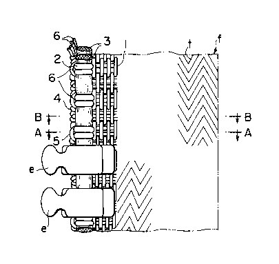
FIG. 1 is a plan view of a fastener stringer
having a woven stringer tape according to this inven-
tion;
FIG. 2 is a cross-sectional view taken along
line A-A of FIG. 1;
FIG. 3 is a cross-sectional view taken along
line B-B of FIG. 1;
FIG. 4 is an exploded perspective view of the
woven structure of the fastener stringer;
FIG. 5 is a plan view of a modified fastener
stringer having a knitted stringer tape according to
the invention; and
FIG. 6 is a fragmentary cross-sectional view of
the fastener stringer of FIG. 5.
DETAILED DESCRIPTION
FIG. 1 shows a woven fastener stringer f as one
embodiment of this invention. The fastener stringer f
includes a tape t woven of plural warp yarns 1 and a
weft yarn 2. The stringer tape t has on front and rear
surfaces a pair of core threads 3, 3 woven with the
weft yarn 2 along one longitudinal tape edge simulta-
neously with the weaving of the stringer tape f, and
an edge warp yarn 5 laid in successive turnover por-
tions 4 of the weft yarn 2 which are arranged along
the one longitudinal tape edge. In FIGS. 1 through 3
the edge warp yarn 5 and the turnover portions 4 of

2081988
the weft yarn 2 are shown as projecting from the core
threads 3; but actually they bite into the core
threads 3 with substantially no projection over the
circumferential surfaces of the core threads 3 to form
a beaded edge having a substantially circular cross
section so that the resulting stringer tape t can be
sandwiched between upper and lower mold halves (not
shown) reliably without any obstacle when a succession
of coupling elements e are to be formed by die-
casting.
The woven structure of the stringer tape t may
be any of various kinds of known structures. As is ap-
parent from FIG. 4, a pair of conductive wires 6 are
woven with the weft yarn 2 as inserted between the
edge warp yarn 5 and the core threads 3 simultaneously
with the inserting of the edge warp yarn 5. As shown
in FIGS. 2 and 3, the conductive wires 6 are drawn
against the core threads 3 by the edge warp yarn 5 and
the turnover portions 4 of the weft yarn 2 and are
concealed thereby so as to be only partially exposed
from the texture woven of the edge warp yarn 5 and the
turnover portions 4 of the weft yarn 2. However the
exposed wire portions do not stand out on either the
edge warp yarn 5 or the turnover portions 4 of the
weft yarn 2 but only exist inside the woven texture.
FIG. 5 shows a knitted stringer tape t whose

, 2081988
structure includes a core thread 3 laid in and along a
longitudinal tape edge, a conductive wire 6 inlaid in
parallel to the core thread 3, an edge warp yarn 5,
and tightening weft yarns 2 having along the longi-
tudinal tape edge a succession of turnover portions 4
knitted with the edge warp yarn 5 in such a manner
that the conductive wire 6 is concealed thereby so as
to be only partially exposed from the knitted texture.
However the exposed wire portions do not stand out on
either the edge warp yarn 5 or the turnover portions 4
of the weft yarns 2 but only exist inside the knitted
texture.
In order to have a flexibility, the conductive
wire 6 may be a suitable fiber thread with a conduc-
tive foil or wire such as of copper wound around the
fiber thread. Preferably a set of two conductive wires
should be inserted.
Even when the foregoing stringer tape t is sand-
wiched between die-casting mold halves, any core
thread portion is prevented from being caught by the
groove edges of the mold halves and is hence free from
any damage. Further, during the die-casting, since
molten metal penetrates into the woven or knitted tex-
ture of the stringer tape t to join with the conduc-
tive wire 6 integrally, an electric current can be
conducted to the individual die-cast coupling elements

208I988
-
e reliably during a subsequent electrolytic plating
process.
According to the slide fastener of this inven-
tion, partly since the conductive wire the edge warp
yarn are inserted in the stringer tape along the cir-
cumferential surface of the core threads, and partly
since the inlaid conductive wire is concealed by the
edge warp yarn and the turnover portions of the weft
yarn so as to be exposed only partially, the conduc-
tive wire does not stand out on the outer surfaces of
the stringer tape as protected by the edge warp yarn
and the turnover portions of the weft yarn. With this
arrangement, when the stringer tape is sandwiched be-
tween the mold halves, any part of the conductive wire
is kept from contacting the groove edges of the mold
halves so that an electric current can be conductive
to every coupling element, thus causing an improved
yield of production. Furthermore, since the conductive
wire inserted in the stringer tape is concealed so as
to be seen scarcely from outside, it is possible to
improve the appearance of the slide fastener.

Representative Drawing
A single figure which represents the drawing illustrating the invention.
Administrative Status

2024-08-01:As part of the Next Generation Patents (NGP) transition, the Canadian Patents Database (CPD) now contains a more detailed Event History, which replicates the Event Log of our new back-office solution.

Please note that "Inactive:" events refers to events no longer in use in our new back-office solution.

For a clearer understanding of the status of the application/patent presented on this page, the site Disclaimer , as well as the definitions for Patent , Event History , Maintenance Fee  and Payment History  should be consulted.

Event History

Description Date
Inactive: Reversal of expired status 2012-12-10
Time Limit for Reversal Expired 2012-11-05
Letter Sent 2011-11-03
Letter Sent 2009-03-05
Inactive: Payment - Insufficient fee 2008-12-15
Inactive: Office letter 2008-12-15
Inactive: Late MF processed 2008-11-05
Letter Sent 2008-11-03
Inactive: IPC from MCD 2006-03-11
Grant by Issuance 1996-07-02
Application Published (Open to Public Inspection) 1993-05-06
All Requirements for Examination Determined Compliant 1992-11-03
Request for Examination Requirements Determined Compliant 1992-11-03

Abandonment History

There is no abandonment history.

Fee History

Fee Type Anniversary Year Due Date Paid Date
MF (patent, 5th anniv.) - standard 1997-11-03 1997-10-16
MF (patent, 6th anniv.) - standard 1998-11-03 1998-08-14
MF (patent, 7th anniv.) - standard 1999-11-03 1999-08-18
MF (patent, 8th anniv.) - standard 2000-11-03 2000-08-10
MF (patent, 9th anniv.) - standard 2001-11-05 2001-10-17
MF (patent, 10th anniv.) - standard 2002-11-04 2002-10-17
MF (patent, 11th anniv.) - standard 2003-11-03 2003-10-16
MF (patent, 12th anniv.) - standard 2004-11-03 2004-10-07
MF (patent, 13th anniv.) - standard 2005-11-03 2005-10-06
MF (patent, 14th anniv.) - standard 2006-11-03 2006-10-06
MF (patent, 15th anniv.) - standard 2007-11-05 2007-10-09
MF (patent, 16th anniv.) - standard 2008-11-03 2008-11-05
Reversal of deemed expiry 2008-11-03 2008-11-05
MF (patent, 17th anniv.) - standard 2009-11-03 2009-10-14
MF (patent, 18th anniv.) - standard 2010-11-03 2010-10-25
Owners on Record

Note: Records showing the ownership history in alphabetical order.

Current Owners on Record
YKK CORPORATION
Past Owners on Record
MASAHIRO KUSAYAMA
SHUNJI AKASHI
TSUTOMU YONEZAWA
Past Owners that do not appear in the "Owners on Record" listing will appear in other documentation within the application.
Documents

To view selected files, please enter reCAPTCHA code :


To view images, click a link in the Document Description column. To download the documents, select one or more checkboxes in the first column and then click the "Download Selected in PDF format (Zip Archive)" or the "Download Selected as Single PDF" button.

List of published and non-published patent-specific documents on the CPD .

If you have any difficulty accessing content, you can call the Client Service Centre at 1-866-997-1936 or send them an e-mail at CIPO Client Service Centre.


Document
Description 
Date
(yyyy-mm-dd) 
Number of pages   Size of Image (KB) 
Claims 1994-03-29 1 22
Abstract 1994-03-29 1 20
Description 1994-03-29 7 201
Drawings 1994-03-29 4 74
Abstract 1996-07-01 1 25
Description 1996-07-01 7 224
Drawings 1996-07-01 4 65
Claims 1996-07-01 2 106
Representative drawing 1998-10-14 1 11
Maintenance Fee Notice 2008-11-12 1 171
Late Payment Acknowledgement 2008-11-12 1 164
Maintenance Fee Notice 2011-12-14 1 172
Correspondence 2008-12-14 1 17
Fees 2008-12-02 1 58
Correspondence 2009-03-04 1 14
Fees 2008-12-02 1 68
Correspondence 2008-12-15 1 51
Fees 1996-10-21 1 56
Fees 1995-10-19 1 63
Fees 1994-10-16 1 75
Examiner Requisition 1995-04-17 1 51
PCT Correspondence 1996-04-18 1 34
Prosecution correspondence 1995-10-16 1 30