Une partie des informations de ce site Web a été fournie par des sources externes. Le gouvernement du Canada n'assume aucune responsabilité concernant la précision, l'actualité ou la fiabilité des informations fournies par les sources externes. Les utilisateurs qui désirent employer cette information devraient consulter directement la source des informations. Le contenu fourni par les sources externes n'est pas assujetti aux exigences sur les langues officielles, la protection des renseignements personnels et l'accessibilité.
L'apparition de différences dans le texte et l'image des Revendications et de l'Abrégé dépend du moment auquel le document est publié. Les textes des Revendications et de l'Abrégé sont affichés :
| (12) Brevet: | (11) CA 2081988 |
|---|---|
| (54) Titre français: | FERMETURE-ECLAIR |
| (54) Titre anglais: | SLIDE FASTENER |
| Statut: | Périmé et au-delà du délai pour l’annulation |
| (51) Classification internationale des brevets (CIB): |
|
|---|---|
| (72) Inventeurs : |
|
| (73) Titulaires : |
|
| (71) Demandeurs : |
|
| (74) Agent: | GOWLING WLG (CANADA) LLP |
| (74) Co-agent: | |
| (45) Délivré: | 1996-07-02 |
| (22) Date de dépôt: | 1992-11-03 |
| (41) Mise à la disponibilité du public: | 1993-05-06 |
| Requête d'examen: | 1992-11-03 |
| Licence disponible: | S.O. |
| Cédé au domaine public: | S.O. |
| (25) Langue des documents déposés: | Anglais |
| Traité de coopération en matière de brevets (PCT): | Non |
|---|
| (30) Données de priorité de la demande: | ||||||
|---|---|---|---|---|---|---|
|
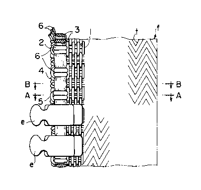
A slide fastener comprising: a pair of woven or
knitted stringer tapes having a pair of core threads
extending in and along their confronting inner longi-
tudinal edges; a pair of rows of die-cast coupling
elements mounted on and along the confronting inner
longitudinal edges; and each of said stringer tapes
including a conductive wire extending along the
respective core thread on its side toward the inner
longitudinal edge, an edge warp yarn extending along
the inner longitudinal edge, and a weft yarn having a
succession of turnover portions arranged along the in-
ner longitudinal edge, said conductive wire together
with said edge warp yarn being incorporated into each
said stringer tapes by said turnovers in such a manner
that said conductive wire is partially concealed with
said edge warp yarn and said turnover portions.
Note : Les revendications sont présentées dans la langue officielle dans laquelle elles ont été soumises.
Note : Les descriptions sont présentées dans la langue officielle dans laquelle elles ont été soumises.
2024-08-01 : Dans le cadre de la transition vers les Brevets de nouvelle génération (BNG), la base de données sur les brevets canadiens (BDBC) contient désormais un Historique d'événement plus détaillé, qui reproduit le Journal des événements de notre nouvelle solution interne.
Veuillez noter que les événements débutant par « Inactive : » se réfèrent à des événements qui ne sont plus utilisés dans notre nouvelle solution interne.
Pour une meilleure compréhension de l'état de la demande ou brevet qui figure sur cette page, la rubrique Mise en garde , et les descriptions de Brevet , Historique d'événement , Taxes périodiques et Historique des paiements devraient être consultées.
| Description | Date |
|---|---|
| Inactive : Renversement de l'état périmé | 2012-12-10 |
| Le délai pour l'annulation est expiré | 2012-11-05 |
| Lettre envoyée | 2011-11-03 |
| Lettre envoyée | 2009-03-05 |
| Inactive : Paiement - Taxe insuffisante | 2008-12-15 |
| Inactive : Lettre officielle | 2008-12-15 |
| Inactive : TME en retard traitée | 2008-11-05 |
| Lettre envoyée | 2008-11-03 |
| Inactive : CIB de MCD | 2006-03-11 |
| Accordé par délivrance | 1996-07-02 |
| Demande publiée (accessible au public) | 1993-05-06 |
| Toutes les exigences pour l'examen - jugée conforme | 1992-11-03 |
| Exigences pour une requête d'examen - jugée conforme | 1992-11-03 |
Il n'y a pas d'historique d'abandonnement
| Type de taxes | Anniversaire | Échéance | Date payée |
|---|---|---|---|
| TM (brevet, 5e anniv.) - générale | 1997-11-03 | 1997-10-16 | |
| TM (brevet, 6e anniv.) - générale | 1998-11-03 | 1998-08-14 | |
| TM (brevet, 7e anniv.) - générale | 1999-11-03 | 1999-08-18 | |
| TM (brevet, 8e anniv.) - générale | 2000-11-03 | 2000-08-10 | |
| TM (brevet, 9e anniv.) - générale | 2001-11-05 | 2001-10-17 | |
| TM (brevet, 10e anniv.) - générale | 2002-11-04 | 2002-10-17 | |
| TM (brevet, 11e anniv.) - générale | 2003-11-03 | 2003-10-16 | |
| TM (brevet, 12e anniv.) - générale | 2004-11-03 | 2004-10-07 | |
| TM (brevet, 13e anniv.) - générale | 2005-11-03 | 2005-10-06 | |
| TM (brevet, 14e anniv.) - générale | 2006-11-03 | 2006-10-06 | |
| TM (brevet, 15e anniv.) - générale | 2007-11-05 | 2007-10-09 | |
| TM (brevet, 16e anniv.) - générale | 2008-11-03 | 2008-11-05 | |
| Annulation de la péremption réputée | 2008-11-03 | 2008-11-05 | |
| TM (brevet, 17e anniv.) - générale | 2009-11-03 | 2009-10-14 | |
| TM (brevet, 18e anniv.) - générale | 2010-11-03 | 2010-10-25 |
Les titulaires actuels et antérieures au dossier sont affichés en ordre alphabétique.
| Titulaires actuels au dossier |
|---|
| YKK CORPORATION |
| Titulaires antérieures au dossier |
|---|
| MASAHIRO KUSAYAMA |
| SHUNJI AKASHI |
| TSUTOMU YONEZAWA |

