Note: Descriptions are shown in the official language in which they were submitted.
2082~8,X
90R060
ELECTROTILTABLE MATE~IAL (Tilter)
Gordon W. Culp
Field of the Invention
The present invention is generally directed toward actuators and
more specifically to tilting electrodeformable actuators having a
unidirectional-gradient electroshearable material.
Background of the Invention
Referring to U. S. Patent 4,736,132, Piezoelectric Mirror and
Grating, issued ~ April, 198~, described are optical positioning devices
1~ comprising pie70electric body segments with surface portions that rotate
by mechanical shear in response to an applied electric potential.
Piezoelectric segments of this device shear uniformly because
piezoelectric segments are uniformly polarized. Whole body rotation
requires support of shear body segments by an extension of an electrode,
- ~
, . - , , , - "
, ~ , : . , : . : . . .
2 2~82~8 1
usually the central electrode. Such support ls appropriate for the
relatively small forces imposed by the selF-weight of each piezoelectric
segment and of the optical element portion attached thereto, but is not
appropriate for the relatively large ~orces pertinent to lndustri~l
actuators and motors.
Re~erring to U. S. Patents ~,928,030, Piezoelectric Actuator~ issued
22 May, 1990, and 5,043,621 issued 27 Aug., 1991, described are shear
piezoelectric devices that forcefully actuate in a direction parallel to
the direction in which one shear face translates relative to an opposite
shear face. Surface portions of piezoelectric shear body segments that
rotate in the act of shearing are not used other than to provide the
mechanical compliance needed for shear deformation. The shear modulus of
most ferroelectric ceramic piezoelectric materials is lower than all
other moduli.
Referring to Applicant's pending patent Biaxial Transducer, Ser. No.
07~726,441 filed 2 July, 1~91, described are methods of providing
relative strain with negligible stress in the plane between bonded or
integrally manufactured bodies, for example, the junction between a shear
pie70electric member and a thickness-mode pie~oelectric member. The
disclosure teaches methods of varying the piezoelectric shear
responsivity radially from an axis and linearly with distance from the
axis. Also taught are methods of achieving radially varying responsivity
wlthin a piezoelectrlc shear segment using heat gradients, radiation
gradlents, material properties gradients, and electrodes having
nonhomogeneous electrical properties.
;~
. . . ~ ., ~
'~ ~
:....... .
2~8208~.
Referring to Applicant's pending Ser. No. 07/708,643, Twisting
Actuator tTwister), filed May 31, l991, described therein are means of
providing rotation of a broad surface of an electrodeformable body about
an axis parallel to the broad surface by the use, among o~hers, oP ~
radial gradient of responsivity, that is clearly distinct from the linear
responsivity gradient of the present invention. Also taught in
Applicant's pending 07/803,804 filed Dec.9, 1991, a Division o~
07/70a,~43, ls the use of poslt1cn sensors to measure a composite of
coacting angular and linear accelerations acting on the broad surface,
this measurement being clearly distinguished from the measure~ent of
angular acceleration alone by the present invention.
Referring to Applicant's pending patent DC Traveling Wave Motor,
Ser. No. 07/492,152 filed March 13, 1990, will issue February ll, 1992 as
5,087,852, described is a direct current traveling wave motor using face
shear waves of a piezoelectric lining of the stator. Waves are generated
by the enhancement of electric field intensity due to the presence of
rollers in rolling contact with the piezoelectric lining. The slope of a
shear wave is highest in the region of the highest field intensity.
Rollers therefore roll "downhill" on the locally sheared lining faces,
and by traction through radial compression a~fect sha~t rotation. Large
traveling waves require thick piezoelectric material, and concomitant
high activation potentials. Novelties of the present invention will be
shown to concentrate lower potentials by means of electrodes, thereby
~ achieving relatively high electric field intensi~ies which elicit
correspondingly larger mechanical wave amplitudes.
', ~
:
.
` ` 4 2~82~ 1
Objects of the Invention
The primary object of the Electro~iltable Material ~ ter) is
the forcible tilting of the surface of a mater~al, about an axis of the
surface that is perpendicular to the direction of the
unidirectlonal-gradient in the electroshearable material, in response to
an applied activation signal.
A further object of the tilter is the forcible tilting of a
surface wlth zero stress and large strain at interfaces between two or
more tilters bonded together and oppositely activated.
Another object of the tilter is the forceful positioning of an
object, such as a motor shaft, by rolling traction induced by a tilter.
. Other objects are:
linear forceful positioning of one or more rollers in rolling contact
- with an object, thus moving and positioning the object;
rotary forceful positioning of one or more rollers in rolling contact
with an object, thus moving and positioning the object;
positioning entailing no friction;
relatively high electrical and mechanical efficiency;
high speed of positioning;
unlubricated operation and activation in a vacuum without contamination;
uncooled operation;
ob~iation of conventional bearings;
operation in zero and microgee environments;
, . ~ . .
- . . :, . ~ , .
~V~208~.
operation as a converter of mechanical to electrical energy (generator);
operation in hostile environments;
obviation of sliding electric commutators
operation by a wide variety of electrical power types;
tilting a radiation interactive surface, where said radiatlon includes
light, electromagnetic radiation, acoustic waves, fluid flow, plasma and
bunched particles;
accurate measurement of angular acceleration;
movement of electrostatic charges;
fluid flow resistance control;
and valves for accurate control of fluids.
Brief Description of Figures
Fig. 1 is a perspective inactivated view of a linear embodiment
of the tilter.
Fig. 2 is a perspective activated view of a linear embodiment of
the tilter.
Fig. 3 is a six-part animated sequence of action of the apparatus
of Fig. 2.
Fig. 4 is a perspective view of a rotary motor embodiment of the
tilter.
Fig. 5 is a cut-away perspective view of the apparatus of Fig. 4.
Fig. 6 is a graph of activation parameters that vary with
distance from the tilting surface.
,
,
:
,' .
6 2~82~81
Fig. 7 is a schematic of an electrical activation system of the
tilter.
Fig. 8 is a perspect~ve view of the tilter with klltable
radiation interactive surfaces attached and prox1mate tllt position
detectors const7tuting an angular acceleration sensing embodiment.
Detailed Descrlption
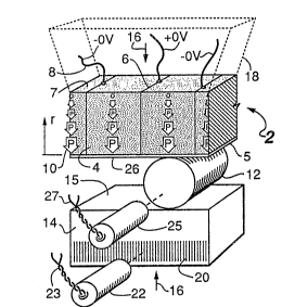
Referring to Fig. 1, shown is a perspective view of the quiescent
~electrically inactivated) state of a linear actuator application of the
electrotiltable material, comprising an electrotiltable actuator body
generally indicated 2, support means 18 phantomed for clarity, roller 12,
and forcibly positioned object 14. The actuator optionally includes
position sensing means 22, 25.
The electroshearable actuator body 2 further comprises
electrotiltable body segments hereinafter referred to as tilters 4,
1~ separated by electrodes 6. In this example embodiment, tilters ~ are made
of electrotiltable material that is piezoelectric and having a
unidirectional gradient of electroshear parallel to film electrodes 6.
Although described in the context of, but not limlted to piezoelectric
materials as an example, it is understood that tilters are made of
electrodeformable material that causes forcible deformations similar to
those obtained piezoelectrically.
- .: , . . . .
. ' '
. '
,~, '
7 ~8208~
Continuing with the piezoelectric example, each tilter 4 is
polarized P in the direction indicated by arrows 10, the sizes of khe
arrows indicating the variation of responsivity wi~h dlstance from
tilting surfaces 26, and directions of arrows indicating the direct10n of
the unidirectional gradient of responsivity. Electrodes 6 between t11~ers
4 are connected to separate sources of variable elec~r1c potent-lal
(omitted for clarity) by leads 8. The electrotiltable actuator body 2 is
affixed to support means 18 by bonding or integral construction at
surface 7 of the support means. The embodiment illustrated uses
electrically non-conducting roller 12 and electrically non-conducting
support means 18. Optional embodiments include one or more insulating
sheets, for example insulative coating 5 on tilting surfaces 26, and
between electrotiltable actuator body 2 and support means 18, allowing
construction using electrically conducting materials such as metals,
cermets and the like. Support means 18 is considered fixed in space while
positioned object 14 and roller 12 move relative thereto. ~ilting surface
26, roller 12, and traction surface 15 of object 14 are in tractive
contact by dint of normal forces 16. Positioned object 14 is constrained
to translate in direction 30 (Fig. 2) parallel to the rolling direction
29 of roller 12. Sensor 22 provides position signals related to the
position of object 14 through leads 23 to sensor signal conditioner 36
(Fig. 7) and then to controller 31. One sensor embodiment uses ~iducial
marks 20 in the form of an optical grating. ~oller position sensor 25
provides a signal indicative of the position of roller 12 through leads
27 to sensor signal conditioner 38 and then to controller 31. Sensor 25
can indicate the times of passage of the edges of roller 12.
. .
:-
- ,
,: :
:
8 i~ 8 ~.
Fig. 2 illustrates activation of the apparatus of Fig, l by
positive voltage +Y and negative voltage -Y applied to leads 8, The
potentials fill tilters 4 with electric field intensity E between fllm
electrodes 6 in direct10ns indicated by arrows 24, perpend~cular to khe
planes of electrodes 6, Again llsing the piezoelectric example, in each
tilter 4 the electric field E and the d1rection o~ unidireçtional
polarization gradlent P are therefore perpendicular, The polarization and
the electric field, ac~ing in concert, induce a gradient of shear
deformation in tilters 4, causing tilting surfaces 26 to change slope,
Predetermined electric potentials cause alternating slopes of the tilting
surface, the causal traction surface in contact with roller 12 that
forces the roller to ro~ate in direction 2a and thus move in direction
29, thereby forcing object 14 to move in direction 3~ by rolling
traction, As object 14 proceeds in direction 30 in the figure, potentials
applied to leads 8 are adjusted so that the slope of the tilting surface
perpetually favors further positioning in the desired direction.
The slope is smoothly adjustable from zero slope to maximum slope
by adjusting the applied potentials, The force is proportional to the
slope and to the normal force, The speed is proportional to the rapidity
with which potentials are changed, Mechanical power is proportional to
the force and to the speed,
When the order and timing of the potentials applied to leads 8
are re~ersed, the tilt slopes are reYersed, causing object 14 to
translate in the direction opposi~e that shown in the figure.
,- , , . , ~
,
- ~ ~
- ,
~: ,
9 2~8~
It should be noted that adjoining tilters are controlled to have
opposite slopes and have common side surface contact areas which shear
with equal magnitudes, thereby eliminating content10us stress wh~le
allowing relatively large stra-ins. ~t is emphasized that tilters that are
not cooperatively activated relegate a substantial portion of the
electromechanical transductlon to internal stress that may cause failure
of a device by fatigue, if not by outright rupture.
Referring to Fig. 3, shown is a six-part animated sequence of the
action of the apparatus of Fig. 2. An arbitrary cycle begins at position
3a when roller 12 is at the junction between two tilters at a time when
there is zero slope on the tilting surfaces. The clock hand on the en~ of
roller 12 indicates relative rotary position during the sequence.
Position 3a reflects ongoing previous motions 29 and 30 of roller 12 and
of object 14, respectively. At positions 3b and 3c, potentials have risen
on the tilter electrodes to change the slopes of the traction surfaces,
thus continuing rolling of roller 12 and moving of object 14. At position
3d, potentials have increased to approximately their maxi~um magnitudes
and the tilting traction surface slopes are maximum. At positions 3e and
3f~ potentials are approaching minimum values, tilt slopes approach
minimum values, ending a cycle with the beginning of a new cycle at
position 3a.
Mechanical actions are shown greatly exaggerated in the figures
for clarity. Although only one or a few rollers are illustrated, the
power delivered by a device is proportional to the number of rollers used
because the total power is the sum of the power contributed by each
: .,
~ .:
-` 2~2~
~o
roller. Tilters are in practice relatively thin in the direction of the
applied electric field (Fig. 2) relative to their broad d~mensions. There
are usually many segments withln the projected width of a slngle roller
or o~her motivated object. The width of rolllng contact between roller lZ
and tilting surface 26 is less than the wldth of t~lter 4.
Referr1ng to Fig. q, shown is a perspectlve end aspect of a
rotary embodiment of the present invention, compris1ng positioned object
14, in this case a rotatable shaft, rollers 12, tilters 4, and support
means or housing 18. The motor of Fig. 4 is shown rotatlng shaft 14 in
direction 30. Position measuring sensors and electrical connections are
omitted for clarity.
Referring to Fig. 5, shown is an oblique section of the motor of
Fig. 4, indicating the relationships between components. Also shown is
the direction of the unidirectional electroshear gradient of the
piezoelectric exemplary embodiment, indicating decreasing responsivity
"a" in direction "r."
Referring to Figure 6, graphed is responsivity "a" as a function
of distance "r", in which ~Ir~ is given more than one meaning depending on
the context of the following description. Responsivity has a maximum
value, A, near the traction surface (26, Fig. l) and decreases linearly
to zero responsivity at the location, R, at the supported surface (7,
Fig. l). Since responsivity is made zero at supported surface 7, no
tilting occurs in the attachment plane to support means 18, even when
tilting surfaces 26 are fully tilted, as clearly illustrated in Fig. 2.
In addition to the aforementioned obviation of bond stresses between
b
. : ` ` ' '
11 2~2~8 1
adjacent tilters, the absence of tilt at support surfaces 7 also proYides
the strength and rigidity expected of a solid actuat~ng body wtthout
stress.
Referr1ng to Fig. 7, shown schematically 1s an eleckrical
activation system for the rotary motor of Fig. 5, generally ind1cated 50,
for operation of apparatus using the electrotlltable material of the
present invention. Activation system 50 comprises controller 31 and
sensor signal condit10ners 36, 38. Controller 31 includes input ports for
activation instructions 32, electrical power 33, and status data output
34. Sensors 22 and 25 provide respective position signals to signal
conditioners 36 and 38 by way of respective connections 23, 27. Signal
conditioners 36, 38 provide respective position signals 40, 42 to
controller 31. Controller 31 compares positions with those included in
the activation instructions 32, any error being compensated for in
controller 31 by adjustment of the n drive signals 35. Drive signals 35,
including timing, amplitude, and slew rate, are adjusted by controller 31
in a manner predetermined to produce efficient and smooth operation of
the device.
Alternate embodiments of the present invention have additional
electrotiltable actuator bodies attached to the positioned object or
shaft so as to offer two traction surfaces for each roller, thereby
doubling the force of actuation. Rotary embodiments with both stationary
and rotating tilting bodies require more compl-icated controlling means,
and require electrical co~mutation. Stator-only embodiments wherein the
size of segments is increased slightly, to effectively provide the
actuating
.
-:, :, ,. - ~ :
::
: : . - : .
; .
.. , : .
., ... 1 : .
.
2V~V8 1.
force otherwise available from multiple tilting body embodlments, are
therefore preferred.
The preferred control loop method, implicit but no~ eYident in
the figures, uses electric signals from the tilters themselves, For
example, the exemplary piezoelectric tilters are electromechanically
reciprocal, converting electrical energy to mechanical work and the
converse. The piezoelectric tilters therefore respond electrically to an
external force applied to the tilting surface, such as the force of
passing rollers. Roller force responses are superimposed on the applied
potentials of the drive signals in leads 35 during operation. Roller
electrical responses are extracted by controller 31 for use in feedback
signals that enable ~ore efficient system operation.
The use of electromechanically reciprocal embodiments of the
tilter allows operation of a diverse assortment of apparatuses such as
generators by converting mechanical into electrical energy. By way of
example, forceful action in direction 30 ~Fig. 2) provided by an external
mechanical power source generates bipolar alternating electrical
potentials in leads 8. Frequency of produced electrical power is
proportional to roller speed, roller spacing, and tilter spacing along
the rolling path. Potential produced is proportional to normal force 16
and the effective responsivity of the tilter material. The power produced
is proportional to the potential and to the frequency.
... ' ' :
- .
13 2~2~8~
There are many ways to vary the responsivity, a, with the
distance r when producing grad~ent electroshearable materlals, some of
which are disclosed in Applicant's copending application s~rlal number
07/708,643 filed May 28, 1991, entitled Twisting Actuators, which is
incorporated herein by reference.
A gradient shear piezoelectric body segment may be made by a
~ethod wherein ~he body has a maximum uniform piezoelectric shear
sensitivity. The segment is then subjected to a linear gradient of
radiation intensity, a, that varies with R as in Fig. 6, and for a
predetermined time, resulting in a linear variation o~ its shear
responsivity.
In another method, a piezoelectric body segment may be made
having maximum uniform piezoelectric shear responsivity and is then
subjected to a linear temperature gradient, a, as in Fig. 6 for a
predetermined time, resulting in linear shear sensitivity.
Using another alternate manufacturing method, piezoelectric shear
segments can be made with maximum uniform shear sensitivity and are
assembled with graded fi)m electrodes. -rhe electrical conductivity/ a, of
each graded electrode varies with R as in Fig. 6. Electrode edges at the
supported body surface, having zero conductivity, may be electrically
grounded for stability, allowing support means or housing 18 to be made
of electrically conducting material. In practice, graded electrode
i~pedance and concomitant electric field intensity distribution are
complex rather than purely resistive. Therefore the gradient of electric
field intensity is linear only with a prescribed frequency content of
electrical activation.
; ' , ~ :
.. .-.
.: ; : ~ : .
- , ~ .- ~ ,: ... - , . ~ ....
. , . - . ., -
.
2082~8~
14
An additional manufacturing method treats uniformly maximally
shear sensitive ferroelectric segments with a non-uniform electric
!,~ polarizing field intensity, resulting in linearly varyin~ shearsensitivity. Additional alternate methods comprise various comblnatlons
of the aforementioned methods.
For a more detailed discussion of how to make piezoelectric
materials with varying polarization or electric field magnitudes that
depend on position, see Applicant's application titled Biaxial
Transducer, serial number 07/726,441 filed aul~ 2, 1991 which is made a
part hereof and hereby incorporated to this application by reference.
A further use of the electrotiltable material is the positioning
of optical elements such as mirrors and gratings. Optical elements
attached to the tilting surfaces provide angular positioning while
retaining the a~orementioned benefits of an essentially solid structural
unit with durable support means, an improvement of Applicant's related
art U. S. Patent 4,736,132 titled Piezoelectrie Mirror and Grating,
issued April 5, 1988, which is incorporated herein by reference.
Re~erring ta Fig. 8, shown in perspective portion view is an
activated radiation interactive embodiment of the tilter similar to that
described with respect to Fig. 2, comprising short tilters ~djacent to
long tilters, support means 187 and radiation interactive elements 52
attached to the long tilters. The short tilters provide stressless
lateral support for the long tilters. Radiation interactive elements 52
of the illustrated embodiment are extended to cover the preponderance of
the tiltiny surface area. When deactivated (potentials as in Fig. 1),
radiation interactive elements 52 lie in a plane in embodiments
benefiting therefrom.
, .. ; ~ :
'. ' ' : : :
.. , . : : ~
2~8208~
2adiation interactive elements 52 have radiation interactive
surfaces 58 which are impinged by radiation. Radiation includes
nonexclusiYely9 in accordance with a particular applicat1On,
electromagnetlc radlation, coherent light as from a laser, ~n~rared and
ultraviolet radiation, radio waves, m1crowaves, millimeter waves, mov1ng
fluid, fluid having wavelike perturbatlons, plasma, bunched partlcles and
acoustical waves. Interaction includes, depending on the particular
application, a combination of focusin~, bunching, valving, turbulating,
direction changing, absorption, reflection, refraction, and diffraction
predicated on the selection of material and morphology of the radiation
interactive surface 58. When activated with electrical potentials of a
first polarity as illustrated in figure 8, radiation interactive elements
52 are tilted in directions 60, while application of opposite polarities
tilt elements in the direction opposite directions 60. Bipolar-responsive
electrotiltable materials, such as those exemplified by the piezoelectric
gradient shear materials, provide twice the angular tilt as materials
responsive only to monopolar activating signals.
At each time instant, the long tilters 4 can be tilted at the
same angle, such that all interactive elements 52 will interact with the
incoming radiation at the same angle. For embodiments in which each
interactive radiation element 52 is a stripe of a grating, the tilting
provides angular adjustment of the stripes.
A variant (not illustrated) comprises an electrodeformable body
similar to that of Fig. 2 wherein tilters are oF equal height and the
tilting surface 26 is clothed in conterminous radiation interactive
16 2~82~
elements such as strips of mirror or of grating. This variant tilts even
numbered interactive segments in one direct~on and odd numbered segments
in the opposite direction, providing a blazed grating with electrlcally
adjustable blaze angle. In the inactivated state, the radiation
interactive surfaces 58 lie at a predetermined angle relative to the
general tilting plane, thls angle includ1ng the zero anyle such that
radiation interactive elements lie in a plane when 1nactlvated, thereby
changing a grating into a plane mirror. The fully clothed variant
advantageously strengthens the apparatus by fully supporting interactive
elements, obviating cantilevered element edges as shown in Fig. 8.
Tilters having uniform height benefit from full mutual side support, and
interactive surfaces lie in a plane in the inactivated state, allowing
vigorous grinding, polishing, and coating with reduced likelihood of
damage. The electrically adjustable blazed grating thus constituted
provides a relatively shallow tilt angle in the range of zero to 20
milliradians of angle, providing practical blazed grating performance in
applications requiring grazing incidence such as very high power laser
resonator optical elements. Further, application of separate and distinct
electrical potentials to the electroshearable body segments provides a
slowly varying spatial distribution of blaze angle and element tilt while
incurring negligible internal stress.
Yet another embodiment of the tilter uses a single tilter such as
the long element of Fig. 8, having position sensors 22 proximate tilting
surface 58. Subjecting element 52 to angular acceleration about the axis
of tilt causes inertial tilting of surface 58. ~ne of the sensors 22
,
. .
17 2 ~
detects a lesser distance to surface 58 while the other sensor detects a
greater distance. Measurement of the dif~erence of the distances, given a
priori knowledge of the body dimenslons, the body elastic properties, and
the magnitude of the angular acceleration about the tilt axis, provides
means of calibrating the apparatus as a uniaxial angular acceleration
transducer.
In one embodiment of the tilter as an angular accelerakion
sensor, electrical signals are applied to the tilter to maintain the
amount of tilt in the inactivated state, equivalent to maintaining the
measured position difference at a null value. Measurement of the value of
the electrical potential applied to the tilter body that nulls tilt,
subsequent to calibration with a predetermined range of angular
accelerations, provides a measurement coresponding to an angular
; acceleration of interest. This preferred measurement method providesadvantageous accuracy because the tilter remains in the unstrained state,
obviating nonlinearities in both the tilting responsivity and in the
distance measurements made by sensors 22.
The accuracy of measurement of an~ular acceleration increases
with increasing sensitivity of position sensors 22. Preferred position
sensing means cause quantum electron tunneling between sensors 22 and
surface ~8 (Fig. 8). 8ecause the electron tunneling current varies with a
large numeric power of the distance between sensor 22 and sur~ace 58, the
position of surface 58 is maintained at the null position with certainty
bounded by a fraction of an atomic distance, thereby providing adequate
sensitivity for a variety of inertial reaction force measurement
,. . ~ , . .
;
, . . ;
.
- : . .
::
18 2~2~
applicat10ns. In addition, because the null tilt position is mainta1ned
during measurements of angular acceleration, the gap, and therefore the
expected tunneling current also remains constant, avo1ding ~he effects of
the nonlinearity of tunneling current with posltion.
One method of making tilters to measure angular acceleration
consists of epitaxially depositing the electrotiltable mater~al and
electrodes, depositing an insulating support layer, then depositing
position detectors 22 proximate surface 58. Deposition also includes
electrical connections 23 to position detectors 22 and to the
electrotiltable body.
In a variant accelerometer embodiment of the tilter, support 18
of the tilter is a multiaxis positioning actuator such as Applicant's
previously described Twisting Actuator Accelerometer application filed
Dec. 9, l991 serial number 07t803,804. A positionable support provides
means of electrically, secularly adjusting the average distance between
surface 58 and position detectors 22 to compensate for errors in
manufacturing, to correct errors due to drift of position detectors 22,
and to correct for such other changes, familiar to those versed in
transducer arts, which erode system accuracy and sensitivity.
The embodiment variant having the positionable support means 18
provides means of cancelling the effects of linear acceleration in any
direction relative to the direction of shear gradient. For example,
linear accelerations normal to the tilting surface, such as downward on
surface 58 (Fig. 8) reduces the distance between surface 58 and sensors
22. In the tunneling current sensor emhodiment, the linear acceleration
- , . . . . .
. . ,; ,
::: :: :: . ~,
l9 2~2~8~
reduces the tunneling currents of both sensors. Algorithms respons1ve to
the 1nherent nonlinear1ty of tunneling current with distance provide
means of returning surface 58 to its null (vertlcal in F1g. 8) position
by apply1ng the appropriate signal to posltloning suppor~ means 1~. Thls
latter step provides unambiguous measurement of angular acceleration, and
also provides, using a measurement of the corrective signal applied to
support means l~, means of measuring the linear acceleration, Those
versed in accelerometer arts will readily appreciate the ease with which
tilters are embodied as multi-axis inertial measurement units (IMUs).
The Applicant has a copending application for an accelerometer
entitled Twisting Actuator Accelerometer serial number 07/~03,804 filed
12~09/91, which is incorporated herein by reference.
In general, ferroelectric piezoelectric materials have an elastic
rigidity that is inversely proportional to shear sensitivity. As shear
sensitivity is changed along the gradient direction, a layering method
allows tailoring of elastic properties such that each segment can better
sustain operating stresses while providing a prescribed gradient of
responsivity. Tilters, as segments of a rotary actuator and motor
embodiment, are larger at supported surfaces ~ than at tilted surfaces
26. Therefore, structural segment strength that is anisvtropically
decreasing in a radial outward direction favors more efficient operation
without diminishing whole-segment load bearing ability, while reducing
peak activating signal magnitude with a given value of tilt.
.
,
.
~, ~ ,'-
2 ~ 8 ~
The volume of a gradient electroshearable body 1s independent of
the potential applied to lt. The th-ickness of the segments in the
direction of electric field E ~Fig. 2) does not change during excltation,
allowing compress1ve segment packing in a support means such as a housing
(18, Fig. 3). Net segment measurement parallel to polarization direction
(lO, Fig. l) does not change, allowing constant average spacing of
rolling traction surfaces during operation. The measurement in a
direction parallel to a roller axis does not change, thereby avoiding
bonding stress at the supported surface 7. This constant measure also
precludes axial rubbing at contacts between rollers and the traction
surface.
Referring to figures l and ~ (disregarding the rollers 12 and the
object 14), multiple unidirectional-gradient electroshearable material
segments 4, having tilting surfaces 26, can consti-tute the inner surface
portion of a fluid duct ~support means 18), in which a fluid flows. The
~ilting surface, when quiescent, presents to the flow a smooth surface
which does not hinder the flow. When the tilters are activated, the
tilted surfaces initiate more turbulent flow of the flu1d, thereby
increasing flow resistance with increasing tilt angle. As previously
described, segments do not change volume when activated, allowing average
fluid duct cross section area to remain invariant with tilt angle.
However, the inward facing apex edge of a conterminous pair of tilted
surfaces occludes a portion of the duct area, further increasing the
resistance to flow.
.~ : :. . -
:
21 2 ~ ~ 2 ~
In another embodiment a segment width may be pr~determined to
excite periodic turbulation in a selected fluid having a prescrlbed
veloc1ty. Conversely, a fluid having predetermined periodic energy
content may relinquish a portion of its energy in the con~erslon from
ponderomotive to electromotive by an array of gradient electroshearable
segments acting as a generator or as a sensor. The latter may be
responsive to a narrow span of frequencies, such as predetermined
critical frequencies in apparatus known to evince chaotic behavior.
Referring to figures l and 2 (disregarding the roller 12), the
tilting surface 26 could be placed close to an object such as a duct or
tube wall 15. A fluid flowing in direction 29 between tilting surface 26
and wall l~ can be slowed or stopped by tilter 26 being activated such
that an apex comes close to or touches wall lS.
In another embodiment, two tilters facing one another and having
a fluid flowing between their proximate tilting surfaces can both be
activated such that their apexes approach or touch one another, thus
acting to reduce or stop the flow of a fluid.
Electrode edges of the activated gradient electroshearable array
tilting surface have alternating polarities that act on bunched charged
particles, such as bunched electrons in a free~electron laser. Two
closely facing tilting surfaces provide alternating-direction electric
field intensity known to effect bunching. Spatial frequency in the beam
direction is effected by assembling segments of prescribed width, while
the electric field intensity is remotely electrically adjusted by varying
the potential magnitude on each electrode, in accordance with
predetermined ef~ect of tilt edge apex spacing and applied potential, on
the collective effects on the quality of bunching.
. . .- :
.
.: . ~ .
22 2 ~ $ 2 ~ ~ ?.
Piezoelectric ceramics, typically oxides of lead, zirconium,
titanium and bariu~ are known for relatively high compressive strength
but relatively 'low tensile strength, the ratio being as high as 100:1,
During rolling, and due to the applied contact ~orce needed for ro'll~ng
traction, stresses borne by the piezoelectric segments are 'largely
compressive. Interference assembly in the support means (housing) also
compresses the tilting body annularly. The preferred assembly method
follows the teaching of the rol'ler bearing art wherein all rollers are
inserted to one side between the electroshearable body and the shaft,
then progressively ~oved around until equally spaced. Repositioning of
relatively tight rollers is aided by differential heating and cooling of
components~
Preferred materials of the unidirectional-gradient
electroshearable material are selected so that the contact force remains
within prescribed bounds in a predetermined temperature range. The ideal
choice of materials results in a ~ero sum of products of linear thermal
expansion and length, giving constant contact force throughout the
temperature range, at least when thermal gradients are absent. Selection
of deYice materials, all having very small thermal expansion, allows
predetermined temperature differences and temperature gradients of
components while maintaining contact force within prescribed bounds.
Residual stress due to differential thermal expansion is
compensated for by incorporating into the actuator an element of Biaxial
Transducer, a stress ameliorating element described in Applicant's
copending application Ser. No. 07~726,441~ filed 2 July, l991. ThP
biaxial transducer provides surface dilatation by an electrically
-; :
,, . - :.
.
.
~ , . .
: . ,. .
.. . .: ~
., . , ~
23 2~82~81
controlled circular gradient shear. Dilatation accommodates substantial
strain without incurring internal stress in the plane of the bond between
the actuator of the present invention and the biaxial transd~cer.
Illustrated embodiments show exposed shear bodles ~n F~gs. 3, 4,
5, 7, and 8. Alternate embodiments include shear body surfaces coated
with electrical insulating mater1als such as layer 5, in Figs. l and 2.
Coating materials having elastic limits equal to or greater than those of
the shear body are preferred to eliminate cracking and delamination.
Coatings comprising ceramics such as the high strength compositions used
in automobile engines are preferred for traction surfaces, particularly
when conducting rollers are used. Coating prevents electrical leakage
during operation in conducting media such as gas at low pressure,
conductive liquids such as seawater, or fluids containing conductive
particles. Coatings also distribute rolling contact stress from maximum
stress at the contact surface to a substantially lower value in the
tilting body near the interface of body and coating.
Piezoelectric ferroelectric materials supply a peak-peak edge angle in
the range of zero to 20 milliradians. Although most embodiments of the
peristaltic shear motor are self starting, after an extended quiescent
time, roller contacts may be temporarily deformed. Ancillary star~ing
means are well known to those versed in the electromecha~ical arts and
may be used herewith.
Mechanisms that shorten life of the present invention are few and
relatively benign. Illustrated embodiments show the use of rollers,
whereas balls result in equivalent operation. Rotary embodiments with
- ,. , ~ .
. .: . :
2 ~
24
balls use rotor and stator grooves (not illustrated) as ball guides.
However, balls cause a concentrated stress of contact, also referred to
as a Hertzian contact, that typically has a small circular or el1iptical
contact area. ~ertzian contacts are characterized by high stress and low
stiffness. The rigidity of the Hertzian contact 1s proportional to khe
normal force of contact taken to a relatively large numer1cal power. At
low normal force, rigidity is low. In many applications of rolling balls
such as ball bearings, rigidity never reaches desirably high values
before contact stress rises above those values that cause short life or
outright destruction of the bearing.
In contrast to the rolling ball, the cylindrical roller has a
line contact that is not Hertzian. Normal forces are distributed over the
relatively large area of the line contact, resulting in reduced contact
stress. Rigidity of the rolling line contact is inherently high, even at
initial contact under relatively low values of normal force. Rigidity
thereafter changes relatively little with increasing normal force. Stress
is further reduced by the use of plural rollers, given a predetermined
normal force.
Just beneath the line of contact between roller and traction
surface, the compressive stress in the pie7celectric material reaches a
maximum. Associate~ with the compressive stress is a shear stress that is
approximately equal to one third of the compressive stress.
Rolling element failure is initiated by microsliding and fatigue.
Microsliding is the minute relative sliding of portions of the rolling
contact surface. The amount of microsliding depends on the deformation in
.
:: .; , .. . . . . . . .
- . . .. ~ ,. . .. : -: : .
"
2~2a~.l
the contact, which in turn depends on the magnitude of the applied normal
force and on the curvature of the contacting surfaces. Rollers have
- measurably longer lives than balls, given a normal force and rolling
diameter. Fatigue depends in a complex manner on the normal force and the
repetition rate of strain application and removal. Rollers are preferred
because a relatively low strain of contact results from a given normal
force.
In Applicant's copending application DC Traveling Wave Motor,
Ser. No. 07/492,152 filed March 13, 1990, the taught electric field
intensity that determines the s70pe of the sheared plezoelectric liner
depends on the radius of the rollers, the slope increasing with
decreasing roller radius. In contrast, the present invention determines
electric field intensity by actuator body geometry, responsiveness being
independent of roller radius. Therefore, ~he present invention provides
the improvement of allowing the use of rollers predetermined to be large
enough to relegate rolling contact stress to a value below a prescribed
maximum.
Embodiments and variants of the tilter operate more efficiently
when lubricants are not used. Bearings in the conventional sense are not
used in the present invention because the positioned object, subject to
the normal force of traction, is held in a vise-like grip at all times.
The rolling contact in combination with high relative rigidity results in
constraining the positioned object with greater precision than afforded
by any conventional rolling element bearing having customary clearances.
Relatively long motors provide complete guidance of rollers because
~; - .
2~2~8~
26
travel1ng tilts favor movement of a roller to a location entalling
reduced potential energy. Short motors use roller stabllizers, also
called retainers, famil1ar to those versed 1n the rolling element bearing
arts.
Piezoelectric shear transducers operate most effic1en~1y when
driven with symmetric b~polar s~gnals as taught ~n U. S. Patents
4,928,030, Piezoelectric Actuator, issued May 22, l990, and 5,043,621
issued Aug. 27, l991. Perpendicularity of applied electric field and
polarization directions precludes depolarization in piezoelectric
embodiments. In con-trast, a relatively small potential antiparallel to
the poling direction applied to a thickness or extension mode
piezoelectric transducer results in altered polarization. Bipolar
electric drive effectively doubles the mechanical response of shear
transducers compared to thickness and extension piezoelectric mode
devices, these latter being limited essentially to monopolar electric
drive. In addition, the piezoelectric coeff-lcient of shear responsivity
and the electromechanical coupling factor are generally higher than those
of other modes, an aid to more efficient power conversion.
Piezoelectric shear is a two-dimensional deformation, whereas all
other known modes of deformation are three-dimensional. Two-dimensional
deformation in part allows shear operation at relatively high energy
density without excessive heating, thereby precluding forced cooling in
most applications. Essentially cold operation is an advantage in vacuum
applications such as interstellar space. However, embodiments having
forced cooling channels ~not illustrated) in one or more components are
included in the scope of the present invention.
'
27 2~8~08~
Although piezoelectric actuators are described as an example
embodlment of electroshearable material, any material that forcefully
shears in response to electrical act1vat10n may be used ~n variarlts oF
the present invention. Magnetostrictive materials, electrostrict1ve
materials, assemblages of rolling conductors, magnetically permeable
members and permanent magnets, configured to prov1de the
electromechanical action of gradient piezoelectric shear previously
described, functionally replace piezoelectric shear ~aterials. In
particular, magnetic gradien$ electroshearable materials and
I0 thermoexpansive gradient shear materials may be used.
. ~ . ~, . .
- : . ~ ,. . ~,
,~
- ., : - - - .
. -