Note: Descriptions are shown in the official language in which they were submitted.
2082292
BACKGROUND OF THE INVENTION
Field of the Invention
The field of invention relates to casket construction,
and more particularly pertains to a new and improved multi-
occupancy casket construction wherein the same is arranged for
accommodating a plurality of individuals therewithin.
Description of the Prior Art
Escalating costs and restricted land use are limiting
availability of cemetery space ~or casket burial. To accommodate
such limited availability of land, the invention contemplates
utilization of a unitary casket contalner accommodating a
plurality of individuals therewithin.
2~82292
Prior art casket construction, as typically utilized in
the prior art, is exemplified in U.S. patent 1,887,665 to Truman
wherein a refrigeration casket mounts a plurality of slide doors
to a top surface thereof.
U.S. patent 3,997,949 to Waltz sets forth a casket for
use in side-by-side burials wherein the side walls of the caskets
are provided with normally closed windows and the handles are of
a type enabling the two caskets to be positioned in proximity
relative to one another to accommodate a substantially less than
normal width spacing required of the adjacent caskets.
U.S. patents 3,188,711; 3,823,447; and 1,779,488 are
patents illustrating various handle construction in the prior art
that may be mounted in various relationships relative to caskets
for various purposes of space saving construction.
As such, it may be appreciated that there continues to
be a need for a new and improved multi-occupancy casket as set
forth by the instant invention whlch addresses both the problems
2082292
of ease of use as well as effectiveness in construction ana in
thls respect, the present invention substantially fulfills this
need.
2082292
..._
SUMMARY OF THE I NVENT I ON
In view of the foregoing disadvantages inherent in the
known types of casket constructions now present in the prior art,
the present invention provides a multi-occupancy casket wherein
the same utilizes a unitary casket housing a plurality of
individuals therewithin for buriai. As such, the general purpose
of the present invention, which will be described subsequently in
greater detail, is to provide a new and lmproved multi-occupancy
casket which has all the advantages of the prior art casket
construction and none of the disadvantages.
To attain this, the present invention provides a casket
construction including a central container cavity, including at
least one support member directed medially of the container
cavity, wherein the support member includes a respective first
and second copianar support, with a medially directed copianar
connecting rib accommodating support of a plurality of
individuals upon the respective first and second support plates
2~82292
~.
permitting positioning of the ieg portions of the lndividuals
below the support member within the container cavity. A
plurality of lids are provided to provide selective access to
each individual upon each respective support plate. The
invention further includes 2 cover housing, wherein the cover
housing is mounted upon a medial ledge positioned below an upper
top surface of the side walls, wherein the housing includes
furled cover webs extendable from within the housing to
selectively cover discrete portions of individuals mounted upon
the support member. The invention further includes a partition
wall directed orthogonally between opposed end walls and medially
between the side walls to permit positioning of a further support
member in coplanar relationship relative to the support member to
accommodate a further plurality of individuals thereon within a
single cas~et construction.
My invention resides not in any one of these features
Per se, but rather in the particular combination of all of them
herein disclosed and claimed and it is distinguished from the
2Q~2292
prior art in this particular combination of all of its structures
for the functlons specified.
There has thus been outlined, rather broadly, the more
important features of the invention in order that the detailed
description thereof that follows may be better understood, and in
order that the present contribution to the art may be better
appreciated. There are, of course, additional features of the
invention that will be described hereinafter and which will form
the subject matter of the claims appended hereto. Those skilled
in the art will appreciate that the conception, upon which this
disclos~re is based, may readily be utilized as a basis for the
designing of other structures, methoas and systems for carrying
out the several purposes of the present invention. It is
important, therefore, that the claims be regarded as including
such equivalent constructions insofar as they do not depart from
the spirit and scope of the present invention.
Further, the purpose or the foregoing a~stract is to
enable the U.S. Patent and Traaemark Office and the public
20~2292
generally, and especially the scientists, engineers and
practitioners in the art who are not famiilar with patent or
legal terms or phraseoiogy, to determine quickly from a cursory
inspection the nature and essence of the technical disclosure of
the application. The abstract is neither intended to define the
invention of the application, which is measured by the claims,
nor is it intended to be limiting as to the scope of the
invention in any way.
It is therefore an object of the present invention to
provide a new and improved multi-occupancy casket which has all
the advantages of the prior art casket construction and none of
the disadvanta~ges.
It is another object of the present invention to
provide a new and improved multi-occupancy casket which may be
easily and efficiently manufactured and marketed.
It lS a further object of the present invention to
~82~92
provide a new and improved multi-occupancy casket which is of a
durable and reliable construction.
An even further object of the present invention is to
provide a new and improved multi-occupancy casket which is
susceptible of a low cost of manufacture with regard to both
materials and labor, and which accordingly is then susceptibie of
low prices of sale to the consuming public, thereby making such
multi-occupancy caskets economically available to the buying
public.
Still yet another object of the present invention is to
provide a new and improved multi-occupancy casket which provides
in the apparatuses and methods of the prior art some of the
advantages thereof, while simultaneously overcoming some of the
disadvantages normally associated therewith.
These together with other objects of the invention,
along with the various features of novelty which characterize the
invention, are polnted out wlth partlcuiarity in the claims
2Q~2292
.,
annexed to and forming a part of this disclosure. For a better
understanding of the invention, its operating advantages and the
specific objects attained by its uses, reference should be had to
the accompanying drawings and descriptive matter in which there
is illustrated preferred embodiments of the invention.
2~8~292
.
BRIEF DESCRIPTION OF TKE DRAWINGS
The invention will be better understood and objects
other than those set forth above will become apparent when
consideration is given to the following detailed description
thereof. Such description makes reference to the annexed
drawings wherein:
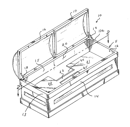
Figure 1 is an isometric illustration of the invention.
Figure 2 is a top orthographic view of the instant
invention.
Figure 3 is an isometric illustration of a cover
housing utilized by the instant invention.
Figure 4 is an isometric lllustration of the casket
construction utilizing a cover housing, as illustrated in Figure
3.
--10--
2382292
Figure S is an isometrlc illustration or the casKet
constructlon inventlon ln an assemblea configuration.
Figure 6 is an isometric illustration of a modification
of the casket construction for accommodatlng plurai palrs of
individuals therewithin.
- 2082292
! --
DESCRIPTION OF THE PREFERRED EMBODIMENT
With reference now to the drawings, and in particular
to Figures 1 to 6 thereof, a new and improved multi-occupancy
casket embodying the principles and concepts of the present
invention and general.ly des1gnated by the reference numeral l0
will be described.
More specifically, the multl-occupancy casket 10 of the
instant invention essentially comprises a central container li,
including a first end wall 12 spaced from and parallel a second
end wall 13, each of an equal predeterm1ned height, with a first
and second respective side wall 14 and 15 arranged parallel
relative to one another and between the first and second end
walls 12 and 13. A top surface of each of the walls 12-15
defines a coplanar perimeter top surface 11a, with the top
surface 11a defining an upper terminal end of the second side
wall 15 hingedly mounting a respect1ve flrst and second
2082292
iid 17 and 16 respect1vely. A respective first and second
mounting length 19 and 18 mount the first and second lids
relative to the second side wall 15. The perimeter top surfaces
lla defines a container opening 20 defined by a predetermined
area, with the rirst and second lids 17 and 16 arranged to
overlie the area when in a lowered position.
A support member 40 is mounted orthogonally within the
central container 11 orthogonally oriented relative to tne walls
12-15, including a first support plate 21 coplanar with a second
support plate 22 and spaced therefrom, with a connecting rib 23
coplanar w1th first and second support piates 21 and 22 arranged
to secure the first and second support plates together to define
a generally "I" shaped configuration. First support plate 21 is
mounted to the first end wall 12, as well as the first and second
side walls 14 and 15. The second support plate 22 is mounted to
the second end wall 13, as well as the first and second side
walls 14 and 15. The support mem~er therefore permits
positloning of a respective first and second individual upon a
respective first and second support plate 21 and 22, with the
20~2292
ndividuals' legs projecting within the first and second slots 24
and 25 defined by the openings between the side walls and the
connecting rib 23.
A medial ledge 26 is arranged parallel to and below the
perimeter top surface lla and includes plural pairs of mounting
bores 27 directed therethrough adjacent the respective first and
second side walls 14 and 15, with each of the mounting bores
receiving a positioning peg 28 mounted to a cover housing floor
of an associated cover housing 29. The cover housing further
includes a central cover housing cavity 31 mounting a plurality
of furled cover webs 32 therewithin, The housing 29 further
includes side wall slots 33 directed through each side wall of
the cover housing 29 in confrontation to the end walls 12 and 13
thereby arranging a slot 33 parallei to each re~pective end
wall. In this manner, a web 32 may be extended as desired from
the cover housing 29 through a respective slot 33 to overlie a
desired portion of an individual cadaver mounted upon a
respective support plate of the first and second support plates
21 and 22. Further, a hook and loop fastener surface 34 (see
-14-
20~2292
Figure 5) may be provided upon the medial ledge 26 for
cooperation with a further hook and loop fastener surface mounted
to the respective web 32 to maintain a web in a predetermined
extended orientation relative to the housing 29.
Figure 6 illustrates a modified aspect of the invention
lOb in contrast to the first modified aspect lOa, as illustrated
in Figure 4, wherein a single unitary cover housing 29 extends,
as indicated in the embodiment of Figure 5, spanning the spaced
side walls 14 and 15, but including a respective first and second
cover web 36 and 37 extending through a forward slot, and a third
and fourth respective cover web 38 and 39 extending through a
rear slot. A partition wall 35 is orthogonally directed medially
between the first and second end walls 12 and 13 parallel to the
first and second side walls 14 and 15 medially positioned between
the first and second side walls. A respective support member 40
is mounted between the partition wall 35 and each respective
first and second side wall 14 and 15. A respective support
member 40 is accordingly associated with a first and third cover
web 36 and 38, and a further support member associated with a
20822~2
respective second and fourth cover web 37 and 39, as illustrated
in Figure 6. In this manner, plural pairs of cadavers may be
mounted within the casket construction lOb, as illustrated in
Figure 6. The hook and loop fastener surface 34 is accordingly
positioned upon a top surface of the partition wall 35
cooperative with each of the cover webs 36-39 to maintain the
webs in a desired extended orientation relative to the housing
29.
As to the manner of usage and operation of the instant
invention, the same should be apparent from the above disclosure,
and accordingly no further discussion relative to the manner of
usage and operation of the instant invention shall be provided.
With respect to the above description then, it is to be
realized that the optimum dimensional relationships for the parts
of the invention, to include variations in size, materials,
shape, form, function and manner of operation, assembly and use,
are deemed readily apparent and obvious to one skilled in the
art, and all equivalent relationships to those illustrated in t~e
-16-
2082292
drawings and described in the specification are intended to be
éncompassed by the present invention.
Therefore, the foregoing is considered as illustrative
only of the principles of the invention. Further, since numerous
modifications and changes will readily occur to those skilled in
the art, it is not deqired to limit the invention to the exact
construction and operation shown and described, and accordingly,
all suitable modifications and equivalents may be resorted to,
falling within the scope of the invention.