Note: Descriptions are shown in the official language in which they were submitted.
20~2~
~/0 91/1741~ PGI`/US91/03136
PIEZORESISTIVE PRESSIJRE TRANSDllCElR
BACKGROUND OF THE :I:NVENTION
The present invention relates to pressure sensiny
transducers. More particularly, the present invention
relates to pressure sensing transducers of the
piezoresistive type.
Piezoresistive pressure transducerr, have a wide
range of applications in any industry where accurate
pressure monitoring is required. Typical industrial
applications include process monitoring, rotating
machinery monitoring and testing, oil exploratian, and
jet and gas turbine engine controls. Piezoresistive
pressure transducers offer many potential advantages in
such applications due to their small size, absence of
moving parts and potential for sensitivity and accuracy.
The heart of a piezoresistive pressure transducer
is a pr~ssure force collector diaphragm having one or
more piezoresistive elements mounted thereon. The
diaphragm with the piezoresistive elements is typically
placed in a pressure cell of some type which maintains a
low pressure or vacuum on one side of the diaphragm and
allows the external medium under pressure to contact the
other side of the diaphragm. A voltage is placed across
the piezoresistive element(s) and as the diaphragm bends
in response to pressure changes, a resistance change in
the piezoresistive element(s) results in a change in the
current flowing through the piezoresistive element(s).
There exists an application in the plastic industry
known as the polymer melt process where accurate
pressure and temperature measurements are essential to
control the process. The pressure and temperature
typically reach up to 15,000 psi and to 800F and above.
The external media béing measured is typically a slurry,
viscous fluid which has corrosive and abrasive
properties and is maintained at high temperatures of up
to 800F. As a result, conventional alloys of steel and
stainless steel exposed to such media are readily
abraded and degraded.
.,
. .
.. ~ . . . .
. ~ ! `. , .
.1 .. ~ ' .
' ' ' ' '' '` ,, , ~ . ~ : '
WO91/~7~1X ~ ~ 2 q ~ ~ P~T/~S~1/03136 !A`, -i
--2--
In order to accurately meas~re the pressure and
temperature of such media, however, the piezoresistive
elements need to be in intimate contact with the
diaphragm deflected by the media. The vaxious
components of the pressure transducer must also be able
to withstand the high temperatures associated with the
polymer melt process. A flush mount force collecting
diaphra~m capable of operating under suc:h high
temperatures with its pressure and temperature sensing
elements integrated on the diaphragm would be ideal.
However, to the best of Applicant's knowledge there is
no known pressure transducer available in the industry
which has components which can withstand the high
temperature corrosive materials used in the polymer melt
process and can provide accurate pressure and
temperature measurements directly. As a result, the
industry has attempted to develop other pressure
transducers that do not locate the piezoresistive
elements on the diaphragm which makes intimate contact
with the corrosive and abrasive media.
In one approach, a stainless steel force collector
diaphragm of approximately 0.005 inch thickness and
0.320 inch diameter having no pressure or temperature
sensing elements mounted thereon is `arran~ed so that it
is in intimate contac* with the media. This diaphragm
is strictly a force collector with no sensing
capabilities. The force collected through the diaphragm
from the media, due to diaphragm deflection, is
transmitted through a tube or a capillary filled with
mercury to a conventional pressure transducer positioned
a safe distance from the external media.
This approach has several distinct disadvantages.
First, the thin stainless steel diaphragm is susceptible
to abrasion that gradually alters its pressure
sensitivity properties, thereby compromising its
measuring accuracy. Second,-the abrasion of the
diaphragm coupled with its exposure to corrosive media
may eventually cause the rupture of the diaphragm. This
is obviously an extreme hazard when the diaphragm
!, . . ~,
:WO 91/17~1X 2 0 ~ 2 ~ ~ .9 PCI/lJS91/03136
--3--
deflection is transmitted to the pressure transducer
throuyh a tube filled with a poisonous fluid such as
mercury. The risk of mercury contamination is
particularly critical in applications where the medical
and food plastic products are being manufactured, such
as the extrusion of food for human and animal -
consumption, such as cereals, dog food, etc. Such
systems are also more complicated, costly and
inconvenient to assem~ly. Such systems are also less
accurate since they do not permit direct pressure and
temperature measurement of the media.
In another approach, the mercury is replaced with
liquid sodium potassium. Although this eliminates
mercury contamination or poisoning hazards, it
introduces an entirely new problem of a creating a fire
hazard since liquid sodium potassium will spontaneously
ignite upon exposure to air when the diaphragm ruptures.
In still another approach, a stainless steel
extended push rod is used to transmit the force
collected by a diaphragm having no sensing capabilities
to the conventional pressure transducer. This approach
eliminates the previous problems associated with the
fluid filled tube, but creates a new set of limitations
to the pressure transducer. It greatly increases the
cost of manufacturing the pressure transducer.
Moreover, it compromises the pressure measuring accuracy
of the pressure transducer and fails to facilitate any
media temperature measurement. Accordingly, there is a
present need for a pressure transducer which has
piezoresistive sensing elements mounted on a diaphragm
which makes intimate physical contact with corrosive and
abrasive materials and can accurately measure such
materials over wide pressure and temperature ranges.
. . - .
'''
.: . ~ . - :- I . .
, , . . :. . :.
. ~ . ,, . - . .. . . .
,
. ~ . . .
` ~, ~ . , . ;
2 0 3 ~ 1 J
WO91/17418 PCT/US9t/03t36
--4--
SUMMARY OF THE INVENTION
The present invention provides an improved
piezoresistive pressure transducer suitable for use in
pressure monitoring of corrosive and abrasive materials
or in a wide variety of other extreme environments
including high radiation environments.
The present invention further provides an improved `~
piezoresistive pressure transducer having a noYel
configuration which protects the piezor~sistive elements
mounted on the diaphragm and has components and
connections that can withstand high temperature
corrosive and abrasive semisolid viscous slurry pol~mer
; melts or similar substances. The piezoresistive
elements of the Wheatstone bridge are oriented and
located so that the pressure sensitivity is maximized,
whi~e the linearity errors of the output voltage of the
Wheatstone bridge in relationship to the appliecl
pressure are minimized.
The present invention further provides a
temperature sensing element on the diaphragm for direct
temperature measurements of similar application of up to - -
;~ 1000F and above. It has the means for accurately
; measuring pressures and temperatures of media of
extremely corrosive nature. ~
The present invention provides a means of ~.
eliminating residual stresses exerted on the force
collecting diaphragm when the pressure transducer is
threaded into its working position in a wall. It also
provides a silioon-on-sapphire diaphragm configured to
maximize the pressure sensitivity and minimize the
adverse connection effects.
,~It further provides a means to minimize adverse
temperature effects through passive temperature
compensation of the piezoresistive pressure sensitive
35 bridge without the necessity for active components, such -
as diodes, thermistors, balcoes, piezoresistive and
others components of like nature.
' ' .
.' ' ' ,
" -; :: :
, : . . .
WO91tl7418 2~ 7~ 9 PCT/US91/03136
-5-
The present invention provides an improved
piezoresistive transducer having a high degree of
accuracy through a wide temperature range, including a
preferred embodiment having an upper temperature range
5 of 700F or higher.
The present invention further provides an improved
piezoresistive pressure transducer having a high degree
of accuracy through an extremely broad pressure range,
including a preferred embodiment having an upper range
of about 40,000 psi.
The present invention provides an improved
piezoresistive transducer employing a piezoresistive
element epitaxially grown or otherwise deposited on a
single crystal, or on a polycrystalline sapphire
diaphragm. The layer-of piezoresistive material is
preferably grown on the major surface of the diaphragm
so as to form a single integral crystal structure with
the sapphire diaphragm. The piezoresistive layer is
preferably of a thickness of about 500 angstroms to
60,000 angstroms with a preferred range of 500 to 7,000
angstroms. One preferred piezoresistive material is
silicon having an impurity doping of boron in the range
of from 5xl0l7 atoms/cc to 2xl02l atoms/cc. Other
,~ preferred piezoresistive materials are various
silicites, nichrome and various cermet materials. The
deposited piezoresistors are preferably arranged ¢using
standard photolithographic masking and etching
techniques) in a Wheatstone bridge configuration with
thin conductive arms connecting the piezoresi~tors to
the contact pads on the sapphire diaphragm.
.
BRIEF DESCRIPTION OF THE DRAWINGS
Figure l is a cross-section through a preferred
embodiment
of the piezoresistive pressure transducer of the present
invention.
Figure la is an end view taken on line la-la of
Figure l of the pressure transducer viewed from the
pressure media side.
.
: - ,~
~: , ::: -.
WO91/17418 2 0 ~ 2 '1 ~ ~ -6- PCT/US91/03136
Figure 2 illustrates a preferred position for the
piezoresistive elements of the Wheatstone bridge and the
temperature sensing element on the hexagonal shaped
diaphragm.
Figure 3 illustrates the arrangement of the contact
pads, the arms, and nodes of the Wheatstone bridge on
the cavity side of the diaphragm. It also illustrates
the preferred orientation of the piezoresistive
elements of the bridge and of the temperature sensin~
element. It also illustrates the hollow inner section of
the pads formed by removing silicon for later deposit of
various metal alloys.
Figure 4 illustrates the arrangement of the contact
pads, the arms and nodes of the Wheatstone bridge on the ~ `
cavity side of the force collecting diaphragm. It ,
illustrates the orientation of the piezoresistive -
elements of the bridge and of the temperature sensing
element. It also illustrates the hollow inner section
of both the contact pads and arms formed by re~moving
20 silicon for later deposit of various metal alloys. `
Figure 5 illustrates the configuration of the
Wheatstone bridge and the locations of the temperature
compensating resistors.
Figure 6 illustrates an embodiment of an overall
assembly for the piezoresistive pressure transducer of
the present invention.
Figure 7 is an end view of the overall assembly of
the pressure transducer shown on the line 7-7 of Figure
6.
Figure 8 illustrates the location of the overall
assembly of the pieæoresistive pressure transducer with
respect to the pressure media being measured.
:.. .: . . ~ . . : , ,
. .,, , : .
~ :. : .. -. ~ . . . .
:- . : ., -.
. ~ . . . - : '
WO 91/17418 ~ ~ ~ PCI/US91/03136
--7--
DETAILED DESCRIPTION OF THE DRAWINGS
The following description is the best contemplated
mode of carrying out the invention. This description is
made for the purpose of illustrating the general
principles of the invention and should not be taken in a
limiting sense. The scope of the invention is best
determined by reference to the appended claims. In the
accompanying drawings like numerals designate like
parts.
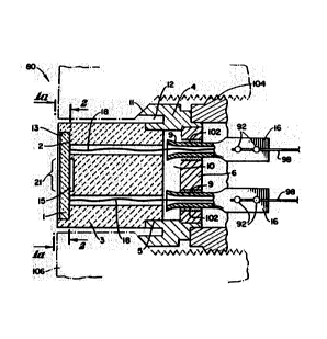
Figure 1 illustrates a cross-section through a
preferred embodiment of a piezoresistive pressure
transducer 80. The pressure transducer 80 may be
connected to an optional resistor board (not shown).
The pressure transducer 80 may be placed within an
overall assembly 34 for protection from the environment.
The assembly 34 has an overall cylindrical shape as
shown in Figure 6. The cross-section of Figure 1 also
represents a section through the axis of the cylindrical
assembly 34. Hexagonal, rectangular or alternate shaped
assemblies may also be employed.
The pressure transducer 80 inc}udes a silicon-on-
sapphire force collector diaphragm 1 mounted within a
recess 13 of a ceramic body 3 by a ceramic glass bond 2.
The diaphragm 1 has a first major surface~which faces a
cavity 15 in the ceramic body 3. As shown in Figures 1
and la, the unsupported area 21 of the diaphragm 1 will
flex into the cavity 15 in response to changes in ' ;
pressure xeceived by the opposing major surface of the ;~
diaphragm 1. As will be described in more detail below,
the diaphragm 1 has thin film piezoresistive elements 7
and 22 deposited thereon on the first major surface of
the diaphragm 1. The piezoresistive elements 7 and 22
reside within the cavity 15 which protects the
piezoresistive elements 7 and 22 from corrosive
materials.
An isolation ring 4 is mounted to the ceramic body -~
3 preferably by a eutectic braze 5. The eutectic braze
5 may be a silver copper alloy having proportions that
are approximately eutectic in composition. The
. , ' .
.. . :: :
.
: ,. . : .
WO91/17418 ' PCT/US91/03136 "-
--8--
isolation ring 4 is welded to a header assembly 6 to
form a secondary chamber 10. The header assembly 6
includes a set of isolation tubes 9. Each isolation
tube 9 is a hermetically sPaled metal feed-through tube
5 lined with glass for electrically isolating an ,
electrical connector 18. Each isolation tube 9 is
mounted to the header assembly 6 through a ceramic glass
seal 102 capable of handling long-term operating ,`
temperatures of about 1000F. Each iso:Lation tube 9 has
10 an outer end which is not lined with glass to form a '
flattened pad 16. The flattened pad 16 provides an area -~
to connect output wires 98 by a durable weld 92. The
opposite end of the,output wires 98 is connected to
connectors 33 A-F of the overall assembly of the
pressure transducer 80 shown in Figure 7. The flattened
pad 16 also provides hermeticity to the secondary ,
chamber 10. This pressure transducer 80 is capable of
handling long-term operating temperatures of about
1000F and pressures of about 40,000 psi and above.
As shown in Figures 1 and la, the electrical
connectors 18 connect the contact pads 19 to the ; '
flattened pads 16. Each electrical connector 18 is '~
preferably made of gold wire and is welded at one end to
contact pad l9. The electrical connector 18 extends
25 through the isolation tube 9. The opposite end of the ''
, electrical connector 18 is welded to the flattened pad
,, 16.
Some of the above mentioned advantages are
accomplished through the following additional features.
, DIAPHRAGM CONSTRUCTION
As shown in Figures la and 2-4, the force
collecting diaphragm 1-is preferably a hexagonal shape
or it may be circular, square, or any other shape
,~ lending itself to ease of production. The diaphragm l
is the main component of the pressure transducer 80.
The diaphragm 1 is a thin deflectable diaphragm of
,~ single or polycrystalline sapphire preferably havirlg a
thickness of 0.003 to 0.070 inches. For example, single,
'
.: -: . .. . . . . . . .
. . .
. :, ,. . ~ . , ~
. . :~ . , , , , -
WO91/17418 ~ 2 ~ ~ ~ PCT/US91/03136
_g_
crystalline sapphire slices of 0.320 inch diameter and
having a thickness of 0.013 to 0.050 inches may be used -;
as diaphragms. The sapphire ls preferably grown through
the Czochralski process in (0001) orientation along the
C axis and the epitaxial single crysta:L piezcresistive
layers grown on the first major surface of the diaphragm
1 through conventional processes.
The diaphragm 1 has a first major sur~ace facing
the ca~ity 15 on which are formed piezoresistive
elements 7 and 22. The piezoresistive elements 7 and 22
are epitaxially deposited by methods such as chemical
vacuum deposition onto the major sur~ace of the sapphire
diaphragm 1 so as to form a crystalline extension of the
sapphire crystal of diaphragm 1. Polycrystalline
piezoresistive silicon may be grown on the first major
- surface through eithe~, for example, sputtering or
chemical vacuum deposition.
The piezoresistive layer is preferably o~ a
thickness of from 500 angstroms to 60,000 angstroms.
One preferred piezoresistive material is silicon having
an impurity doping of boron in the range of fram 5X10¹⁷
to 2X10²¹ atoms/cc. Other preferred piezoresistive
materials are various silicites, nichrome and various
cermet materials.
As shown in Figure 3, the deposited piezoresistive
elements 7 and 22 are preferably arranged (using
standard photolithographic masking and etching
techniques) in a Wheatstone bridge confi~uration with
thin conductive arms 24 connecting the nodes 23 of the
Wheatstone bridge to associated contact pads 19 on the
diaphragm 1.
As shown in Figure 3, a ~emperature sensing element
14 of the same material and construction as the
piezoresistive elements 7 and 22 is positioned in an
area of the diaphragm 1 that is supported by the ceramic
body 3, that is, the non-stress area of the diaphragm 1.
As a result, the temperature sensing element 14 is
virtually impervious to pressure changes yet responds to
:'.:''. : , ' 'l ': : ,, ,',,, . ' ' . ' -
: . . . .
:. :,.. : : . : .. : . . : . . :
WO9l/174t8 2 ~ 3 2 ~ ~ ~ PCT/US9l/03136~ ~
-10
temperature changes in the media in proportion to its
resistive changes.
As shown in Figures 3-4, a single crystal sapphire
is cut along the C axis on a 1012 plane. Single
crystalline silicon may be grown on the sapphire
diaphragm 1 through the conventional processes described
above, preferably on a 1012 plane which yields a silicon
layer on the 100 plane. As shown in Figure 3, a
circular unsupported area 21 of the diaphragm 1 may be
selected as the force collector, SQ that when deformed,
stresses are exerted in the unsupported area 21 of the
diaphragm 1.
When deformed the unsupported circular area 21 of
the diaphragm 1 will exert maximum stress along the edge
of the cavity 15 where the diaphragm 1 is unsupported by
the ceramic body 3 in a direction normal to the edge of
the circle. When the silicon crystallographic plane is
100, the maximum stress will be on the 110 axis. This
configuration is preferred because the maximum
piezoresistive sensitivity of silicon is along the 110
axis on the 100 plane. Therefore, if the piezoresistive
elements 7 are placed along this axis, the exerted
stresses on the diaphragm l will result in a maximum
positive change in resistance. However, if the other
piezoresistive elements 22 are placed perpendicular to
the 110 axis, an equal and opposing negative resistance
change will result in proportion to the exerted stresses
on the diaphragm l. The present invention takes
advantage of this phenomena by providing a four arm
Wheatstone bridge as shown in Figure 3. As a result,
all outputs of the four arm Wheatstone bridge become
additive with some self-compensating temperature
effects.
! . Still another aspect of this invention is to locate
the piezoresistive elements 7 and 22 of the Wheatstone
bridge in a certain region of the unsupported area 21 of
the diaphragm 1. As shown in Figure 2, this area is
defined by an outer radius Rl and an inner radius R2.
The outer radius Rl coincides with the edge of the
.~ .
.
. ,
::, ,:, ~ : ... , . .: .. . . .
:: : :: -
. :, . . : :
:~ :: . : : . . . , :: :
. , -~
. : ~ :. ,. : - : .
A- W~91/17418 20~ PCT/US91/03136
--11--
cavity 15 of the ceramic body 3 where ~he diaphragm 1
becomes unsupported. It can be shown through stress
analysis that there exists a region within the area
definad by the inner radius R2 where the deflection of
the diaphragm l generates zero stresses. In order to
avoid the zero stress region the piezoresistive elements
7 and 22 must be located between the outer radius Rl and
the inner radius R2. The inner radius R2 is preferably
approximately 0.66Rl. ~his location ensures a
relatively uniform stress distribution on the
piezoresistive elements 7 and 22. As a result, the -~
linearity errors of the output voltage of the Wheatstone
bridge in relationship to the applied pressure are
minimized.
Another aspect of this invention is to provide arms
24 to connect the nodes 23 of the Wheatstone bridge to
the pads l9. In this manner, the electrical connectors
18 can be welded or bonded to the pads l9 in a durable ~;
manner without adversely affecting the piezoresistive
measuring and accuracy capability.
As shown in Figure 3, a preferred approach is to
extend the epitaxially deposited silicon used for the
piezoresistive elements, 7 and 22 for the arms 24 as
well. The arms 24 will have a similar composition to
the piezoresistive element 7 except electrical
resistivity will be reduced considerably by increased
boron doping of the arms 24 or by minimizing the squares
of each arm 24 ~y 1ncreasing its width. The arms 24 may
also be partially positioned along a 45 angle to the
llO axis. Such crystallographic axes of silicon are not
pressure sensitive. Therefore, the resistive value of
the arms 24 remain unaltered due to the flexing of the
unsupported area 2l of the diaphragm l. This overall
approach is desirable since the advantage of atomic
bonding o~ silicon to sapphire will also be extended to
the arms 24.
However, this introduces another disadvantage with
respect to the bonding of the electrical connectors 18
to the pad l9. As mentioned earlier, a preferred wire
,
.
. j , , , , , , ~
:~" ' '. ' . . . ' '.' ' '
"' ' '.'. ' ' ' ' ~' . :
'~, . . .. . . ' , '.
WO91/17418 2 ~ 12- PCT/US91/03136
for the electrical connectors 18 i5 gold, aluminum or
platinum. However, welding the electrical connectors 18
to the pads l9 will greatly lower the melting
temperature of the connection because of the formation
of a eutectic composition. This will also drastically
increase the temperature coefficient of expansion. For
example, a gold silicon eutectic alloy formed by the ~;
welding of lead 18 to pad l9 will melt at approximately
420~C. This sharply contrasts with the independent
melting points of silicon and gold which both exceed
1000C. Of course, this introduces appreciable
limitations in measuring manufacturing processes of
higher than 420C.
As shown in Figure 3, the present invention
alleviates this problem by removing the silicon from the
inner section 35 of the pads l9 and depositing other
selective metals to perform the task. One preferred
embodiment is depositing, through conventional means, a
combination of titanium and tungsten alloy. A preferred
composition would be approximately 15% titanium and 85%
~; tungsten by weight. Titanium, independently:or in an
alloy with any other metal, has excellent adhesion
affinity to sapphire. Pure tungsten possesses desirable
electrical and temperature coefficient of:resistance
properties.
In order to ~acilitate the welding or bonding of
the electrical connector 18 to the pad 19, an additional
metal layer is then deposited on the titanium tungsten
alloy layex. A preferr~d additional laysr is platinum,
; 30 however, silver, nickel or other alloys are also
suitable. -
As shown in Figure 4, the silicon or other material
- may also be removed from the inner sections 37 of the
arms 24 extending from the inner sections 35 of the pads
l9 to the nodes 23 of the Wheatstone bridge. Similar
material can then be deposited in the inner sections 37
of the arms 24 as that deposited in the inner sections
35 of the pads l9. This will have the advantage of
lowering the electrical resistivity of the arms 24.
, .
'î. ~ , , ,~ , , , ' . ., .,.............. ,, . . ' ~ .
. ~ ' ' ',' ' ', ' ' ' ~ ' (
~0~19
WO91/17418 PCT/US91/03136
-13-
However, the atomic bonding feature of silicon on
sapphire of the arms 24 may be compromised.
Although the preferred alloy of titanium tungsten
for pads l9 and/or arms 24 is desirable, other alloys
will also function appropriately. For example, pure
titanium, pure tungsten, pure molybdenum, or a
combination of these metals, or a combination of any
other high temperature alloys such as vanadium or nickel
with titanium for adhesion can be used. Aluminum may
also be deposited in the inner sections 35 and 37, of
the pads }9 and arms 24, respectively. However, the
resistance welding of the electrical connectors 18 to
the pads l9 will be somewhat compromised because the
preferred gold wire is not readily weldable to aluminum.
It should be mentioned that the electrical connector 18
may also be platinum, nickel or copper.
As shown in Figure 3, piezoresistive elements 7 and
22 may also be further protected from a hostile
environment by depositing additional layers of materials
tailored for such purposes. Such protective layers will
also further enhance the measurement accuracies and
stabilities. Some preferred layers are silicon dioxide,
silicon nitride, borosilicate glass and aluminosilicate
glass by themselves or in combination. Such layers may
be deposited through conventional processes such as
sputtering, evaporation or plasma enhanced chemical
.; .
vapor deposition. A preferred thickness for the layers
is from 200 angstroms to l0 microns.
~` BRIDGE TEMPERATURE COMPENSATION
The output of the piezoresistive Wheatstone bridge
and its zero offset initial reading are highly
temperature sensitive. Therefore, the pressure
transducer accuxacy is affected by temperature changes. ~-
- Conventional pressure transducers operating in
; 35 temperatures of up to 300F are compensated for
temperature errors through the use of active electronic
components, such as thermistors, balcoes, diodes,
transistors or integrated circuits. However, at this
-
. . . : :: . . , :. , : ~
: , . :. :: . : . ~ . ,.: . ~ .
::: : ... . . . . . . .. : ; , -,: . ~ , : . . ; : . :
.: ... . .
. .. , . . :.
W091/17418 2~2~ ~ ~ PCT/US91/0~136 ~
-14-
time, none of these components are capable of operating
at temperatures of lO00F or above.
The present invention uses only high temperature
resistors having nearly zero temperature coefficients of
resistance to compensate for the adverse temperature
affects occurring at temperatures of up to 1000F and
above. As shown in Figure 5, it compensates for
temperature error by adding a resistor 26 in parallel
and a resistor 27 in series to the associated
piezoresistive element 7. The resistor 26 and 27 have
substantially zero temperature coefficient of
resistances. It can be shown through known techniques
of circuit analysis that a proper combination of
resistors 26 and 27 may be used to minimize the
15 temperature errors at zero pressure. -
Similarly, a combination of resistors 28 and 29 ;~
having substantially zero temperature coefficients of
resistance may be selected to compensate for temperature
error at varying pressure. The latter output
temperature compensation is known as span compensation.
Such temperature compensating resistors 26, 27, Z8 and
2~ may be located on the surface of the diaphragm 1 or
located external to the diaphragm l within the assembly
34 of the pressure transducer 80 shown in Figure 6.
BONDING OF DIAPHRAGN TO CERA~IC BODY
This is accomplished through a devitrifying ceramic
glass 2 which is applied to the diaphragm l and ceramic
body 3 on appropriate areas through conventional
techniques such as by silk screening or by doctor
blading. After application of the ceramic glass 2 to
the proper areas of the diaphragm l and the ceramic body
3 and a drying cycle, the ceramic glass 2 is sealed at
temperatures of between typically 400C to 600C. At
these temperatures, the ceramic glass 2 goes through a
nucleation and a transformation stage and becomes a
solid substance that, unlike glass, will not become
plastic as temperature increases and will not melt at
temperatures of up to 2000F. Through the selection of
:, ~; ,, .; . . :
:- i :: : :.,
2~2 ~1~
-~WO91/1741X PCT/US91/03136
-15-
appropriate compositions, different temperature
coefficient of expansion can be obtained to match that
of the diaphragm 1 and the ceramic body 3. Matching the
temperature coefficient of expansion of these parts is
essential in order to eliminate microscopic cracks ~rom
consecutive heating and cooling cycles that occur during ~
applications. The preferred range of temperature ~;
coefficient of expansion is between 3x:Lo~6 to llxl0-6
/F. Some ceramic glass compounds are commercially
l0 available from Corning Glass and other sources. One
such example is Corning Glass No. 7578.
,
C~RAMIC BODY
The temperature coefficient of expansion of the
ceramic body 3 must match that of the ceramic glass 2,
15 the sapphire diaphragm l and isolation ring 4 in order
to measure high temperatures of up to 1000F and above
and pressures of up to 20,000 psi and above. The
ceramic body 3 must also provide electrical isolation
for electrical connectors 18. An suitable selection is
20 Al2O3, that is alumina, which is basically the same as
sapphire in composition, except that it is non- ?
crystalline and is amorphous. However, preferred
ceramic body 3 is one which has all the following
advantages: improved heat conductivity to minimize
2S temperature response time; high dielectric constant;
non-porous; good adhesion properties for glass ceramic
and brazing sealing; and corrosion and abrasion
endurance against corrosive environments and abrasive
compounds typically encountered in polymer, plastic, ;
30 food and other industries. 5Ome preferred ceramic
compounds are Al2O3, better known as alumina; BEO
brylium oxide, better known as brylua; -Silicon nitride;
Silicon carbide compounds; BEO and Al2O3, brylua and
alumina, better known as chrysoberyl; MgO and Al2O3
35 compounds, better known as spinel; Zerconium oxide and
aluminum oxide systems, better known as zerconia
alumina; SIO2 and aluminum compounds, better known as
andalusite or silliminite; Silicon nitrate and aluminum
. , .
' ~ . '` , ': . . ~ . .
.: . ~ , . ~ - . :
. . ~, :., :
, . .
2 ~ L~
WO91/17418 PCT/US91/03136 -
-16-
oxide compounds; and any other metal oxide compound or
combination compound suitable for ceramics processing
having a temperature coefficient of expansion of about
4xlo-6 to llx10-6/F with high electrical insulation
properties and an optimized thermal conductivity ~f from
0.020 to 0.700 calories cm-sec C.
,~
ISOLATION RING
The isolation ring 4 provides a set of threads 104
to connect the ceramic body 3 including the diaphragm l
to a wall 106 or to a part of the protective assembly
34. The isolation ring 4 also has a pressure sealing
surface ll which functions to seal the pressure media
off ~rom the atmosphere when the protective assembly 34
of the pressure transducer 80 is inserted into the wall
106.
As shown in Figure l, when the pressure transducer
80 is threaded into wall 106, some of the ~orce applied
to sealing surface ll will be transferred to the
diaphragm l through the ceramic body 3. This will exert
undesired residual stresses to the piezoresistive
elements 7 and 22, thereby adversely affectin~ the
measuring accuracy of pressure transducer 80. Such
residual stresses are minimized through an isolation
slot 12 which virtually eliminates or minimizes these
residual stresses.
As the pressure transducer goes through extreme
temperature changes, additional residual stresses may be
exerted upon the diaphragm l if the temperature
coe~ficient of expansion o~ all the parts of the
pressure sensor assembly 80 are not closely matched.
The isolation ring 4 should preferably have temperature
coefficient of expansion of about 4xl0 6 to llxl0-6/F
to match that of the ceramic body 3. The isolation ring
4 must also be brazable, weldable, and corrosion
resistant and have high compressive and tensile
strength. Commercially available nickel iron alloys
with small impurities have such advantages.
,
,~.: , , . : .-, . - . . ~ -
W091/1~418 2 0 8 2 ~1~ PCT/US91/03136
-17-.
A preferred choice for the isolation ring 4 is :
NILO-36 of primarily 36% nlckel and 64% iron with a
temperature coefficient of expansion of 4.7xl0-6/F at
750F, or NILO-42 of primarily 42% nickel and 58% iron
with a temperature coefficient of expansion of
3.4xlO-6/F. Such nickel iron alloys a:re available
commercially under the trade names NILCO, INVAR and
KOVAR. Other preferred choices are INCONEL-718 having a
composition of 51% nickel, 20% chromium, 5% molybonium,
5% niobium and a temperature coefficient of expansion of
about 6.5 to 7.3xlO-6/F at up to about 1000F. Such an
alloy is available commercially under the trade name
INCONEL-718. Other preferred alloy systems are
approximately 44% nickel, 49% cobalt and other
impurities with a temperature coefficient of expansion
of approximately 6xlO 6/F at 600F. This alloy has a
constant modulus of stiffness and it is commercially
available under the trade name C-SPAN ALLOY 902.
,
: . .
.~ . .
.
. .
: . ~ . ,~ . : ... .
: . .~ . . . ~ .; ., , . . : . .
. ' . : . ! , .