Language selection

Search

Patent 2082447 Summary

Third-party information liability

Some of the information on this Web page has been provided by external sources. The Government of Canada is not responsible for the accuracy, reliability or currency of the information supplied by external sources. Users wishing to rely upon this information should consult directly with the source of the information. Content provided by external sources is not subject to official languages, privacy and accessibility requirements.

Claims and Abstract availability

Any discrepancies in the text and image of the Claims and Abstract are due to differing posting times. Text of the Claims and Abstract are posted:

  • At the time the application is open to public inspection;
  • At the time of issue of the patent (grant).
(12) Patent Application: (11) CA 2082447
(54) English Title: BOX STACKER
(54) French Title: EMPILEUR DE BOITES
Status: Deemed Abandoned and Beyond the Period of Reinstatement - Pending Response to Notice of Disregarded Communication
Bibliographic Data
(51) International Patent Classification (IPC):
  • B31B 50/98 (2017.01)
  • B65G 57/30 (2006.01)
(72) Inventors :
  • BOIX JAEN, JOSE (Spain)
(73) Owners :
  • BOIX MAQUINARIA, S.A.
(71) Applicants :
  • BOIX MAQUINARIA, S.A. (Spain)
(74) Agent: MARKS & CLERK
(74) Associate agent:
(45) Issued:
(22) Filed Date: 1992-11-09
(41) Open to Public Inspection: 1994-01-15
Availability of licence: N/A
Dedicated to the Public: N/A
(25) Language of filing: English

Patent Cooperation Treaty (PCT): No

(30) Application Priority Data:
Application No. Country/Territory Date
9201460 (Spain) 1992-07-14

Abstracts

English Abstract


ABSTRACT OF THE DISCLOSURE
This is a box stacker which is related with a box shaping
machine. The boxes come out at the bottom of the machine and
drop by gravity onto a conveyor belt (2) and are conveyed to one
end of this belt (2) where the stacker which is object of this
invention is located. It has upright adjustable guides, two in
front (4 and 5) and two at the rear (6 and 7) which correspond
to the vertical corners of the box, and are at the same time
coupled in pairs to two cross shanks (8 and 9) respectively,
which are in turn coupled at the end to cross shafts (10 and 11)
which are joined by longitudinal screws. The screws turn in
either direction and the upright guides will be adjusted to fit
to the dimensions of the boxes. When one of these lies between
the four upright guides, a pusher (14) goes up and moves the box
to allow room for another one and so on successively. When a
stacked row has been formed, which is automatically counted, it
will be moved by a pusher towards a platform which is formed by
two plates at right angle.


Claims

Note: Claims are shown in the official language in which they were submitted.

THE EMBODIMENTS OF THE INVENTION IN WHICH AN EXCLUSIVE
PROPERTY OR PRIVILEGE IS CLAIMED ARE DEFINED AS FOLLOWS:
1.- BOX STACKER.- Of the type which includes a conveyor
belt which can be connected to a cardboard box shaping machine,
and which furthermore includes at one end of the belt, upright
guides to stack the boxes and an upright pusher; characterized
because the upright guides, two in front (4 and 5) and two at the
rear (6 and 7) are joined to runners (4', 5', 6' and 7') which
are both coupled to two cross shanks (8 and 9) connected to small
end supports (8' and 9'), which are solidary with cross bridges,
one in front (10) and the other at the rear (11), which are
coupled to longitudinal shanks (12 and 13); a horizontal pusher
(17) has been foreseen for a group of boxes (15), and this pusher
(17) is driven in a guide which is connected to the front bridge
(10) which embodies a pneumatic cylinder (18) which works the
pusher; in addition, one of the two front upright guides (4) and
one rear one (6) on that same side are also designed with seat
and fixture plates (19) for a group of stacked boxes (15) when
they are moved by the upright pusher (17); with the peculiarity
that the front upright guides (4 and 5) have lower prolongations
(20) which are carried on rails belonging to side profiles (21),
which are articulated on small supports (22) connected to the
conveyor belt (2), where the ends of these profiles (22) are near
the rear upright guides (6 and 7); there is also an end of run
(16) which counts the boxes of each group (15).
2.- BOX STACKER, in accordance with the above claim,
characterized because the end zone of the conveyor belt (2), from
where the boxes drop off the shaping machine, has been designed
with a slide (1) or stabilizer chute and near this there are some
side plates (3) which can adjust the position of these boxes.

Description

Note: Descriptions are shown in the official language in which they were submitted.


BOX STACKER 2
PURPOSE OF THE _N~VENTION
The present invention, as described in the introduction to
this descriptive report, refers to a box stacker. The boxes drop
by gravity from the shaping machine along a slide to a conveyor
belt which carries them to one end of it, where the box stacker
is located. This embodies a simple and fast mechanism which
regulates the format of the box, and also automatically counts
the number of boxes which fit on each row, so that a number of
rows can be formed, all containing the same number of boxes,
which is possible because once each row is formed, an upright
pusher moves them from the zone of the upright push where each
o these rows are formed. These are arranged in an orderly
manner on upper plates or strips.
ANTECEDENTS OF THE INVENTION
Conventional box stackers are known today which offer some
problems and important drawbacks.
Coming off the box shaping machine, the boxes emerge at the
bottom of the shaping station and fall onto a continuous belt
which forms an integral part of the stacker and they are conveyed
to a sector where an upright stacker piles them up until a row
of stacks is formed.
The main disadvantage of these stackers is the costly
control of the format or size of the boxes which are to be
stacked. On the other hand, only one row can be formed and the
operator must be on the spot to remove it at the precise moment.
DESCRIPTION OF THE INVENTION
To find a complete solution to the problems which are
mentioned in the above paragraph, a box stacker has been designed
which is connected with a box shaping machine and at the bottom
of this machine the boxes fall by gravity, moving along a slide,
on a conveyor belt which embodies side positioning plates. The
boxes are then taken to one end of the belt where the actual
stacker is located. It has adjustable upright guides, two in
front and two at the rear, which correspond to the corners of the

boxes, and at the Same time they are secured to runner~
coupled to two cross shanks whiCh are joined to some small end
supports and secured to cross brackets, one in front and one at
the back, which are connected to two longitudinal shanks. With
this arrangement, when the shanks suitably turn, there will be
a closure or separation between the upright corners, adjusted to
the dimensions of the base of the box. When this lles between
the four upright guides, a pusher emerges from the top of the
lower part, and this moves the respective box to a pre-fixed
height, where it will later be kept in a stable position. The
pusher will later drop to its resting position, at which moment
another box can be fitted between the upright guides, and this
will again be carried up, in the same way as the previous one and
will be moved to an upper position pushed by the second box.
When a group of stacked boxes is formed, which are automatically
counted at the end of each run; this group of boxes will be moved
in a direction that is perpendicular to the conveyor belt by a
horizontal pusher moved by a preferably pneumatic cylinder, and
suit~bly led by a guide of the front cross bridge, where the
pneumatic cylinder is fitted.
The movement of each group of boxes, once formed, will be
performed automatically to enable another group to be formed.
One of the front upright guides and another rear guide on the
same side incorporate upper plates or strips which converge at
right angles, which permit the seating of various groups of
stacks.
To provide an easier understanding of this descriptive
report and forming an integral part of same, a number of figures
are included which show in an illustrative but not a restrictive
way the object of this invention.
BRIEF DESCRIPTION OF THE DRAWINGS
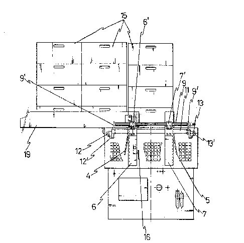
Figure 1.- This shows an elevation projection of the box
stacker which is object of this invention, and it includes a
conveyor belt which leads each of the boxes up to the actual
stack itself.
Figure 2.- This is a profile view of the box stacker, where

several rows of automatically stacked boxes are shown.
Figure 3.- This is a perspective view of the main zone of
the stacker of the invention, which is where each row of boxes
are formed.
DESCRIPTION OF THE PREFERRED FORM OF EXECUTION
Referring to the numeration adopted in the figures, the
stacker of boxes of the invention is associated with a box
shaping machine. At the bottom of this machine, the boxes emerge
and fall by gravity, and advantageously slip down a slide (1),
on a conveyor belt (2) which embodies the novelty of having side
positioning plates (3). Each box is then carried to one end of
the conveyor belt where the stacker of the actual invention is
found.
It has easily adjustable upright corners or guides, two in
front (4 and 5) and two at the rear (6 and 7), which correspond
to the upright corners of the boxes, and at the same time they
are fixed to some runners (4', 5', 6' and 7') which are screwed
parallel to two cross screws (8 and 9), which are coupled to some
small front end supports (8') and rear end supports (9'), which
are solidary to cross bridges (lO and 11) respectively, which are
in turn connected to two longitudinal screws (12 and 13) by means
of small end supports (12' and 13'). With this layout, when the
respective screws turn one way or the other, the vertical guides
are brought close or separated, and are adjusted to suit the
dimensions of the box. When each of these lies b~tween the four
upright guides, a pusher (14) emerges from the top of the lower
part, which moves the corresponding box at the bottom, to a pre-
fixed height where it will later be kept in this stable position.
This pusher (14) will then come down to its resting place, when
another box can then be fitted between the four upright guides,
which will also be lifted up in the same way as the previous one
and it will be moved to an upper position pushed by the second
box, which will occupy the place of the first box. Following
this continuous process, a group or row of stacks will be formed
(15) which will automatically be counted at the end of each run
(16). This group of boxes (15) will be moved in a direction that

is perpendicular to the conveyor belt (2) by means of a
horizontal pusher (17) which is move.d by a cylinder (18), which
preferably will be a pneumatic one and suitably driven by a guide
at the front cross bridge (10), where the pneumatic cylinder is
also fitted.
The movement of each row of boxes (15) once formed, is made
automatically so as to form another one. To do so, one of the
front guides (4) and another rear one (6) on the same side, each
have upper plates or strips (19) which face one another and
permit the seating of various groups of aligned stacks (15). The
upright guides (4 and 5) which are connected to the front bridge
(10) moreover embody lower prolongations (20) (details shown in
figure 1) which fit on and are driven along rails or side guides
(21), which are connected at one end to small supports (22) of
the conveyor belt (2), whereas at the other ends, they are linked
to the rear vertical guides (6 and 7). In this way, each box
that comes off the conveyor belt (2) is perfectly driven as soon
as it enters the stacking zone.
Along the conveyor belt (2) and on either side of it, two
rods have been designed (23) so that the boxes are perfectly
aligned on their run along it (2) and these rods are connected
to small supports (22) and to other (22') similar ones, all
established on either side of the conveyor belt.

Representative Drawing
A single figure which represents the drawing illustrating the invention.
Administrative Status

2024-08-01:As part of the Next Generation Patents (NGP) transition, the Canadian Patents Database (CPD) now contains a more detailed Event History, which replicates the Event Log of our new back-office solution.

Please note that "Inactive:" events refers to events no longer in use in our new back-office solution.

For a clearer understanding of the status of the application/patent presented on this page, the site Disclaimer , as well as the definitions for Patent , Event History , Maintenance Fee  and Payment History  should be consulted.

Event History

Description Date
Inactive: IPC deactivated 2017-09-16
Inactive: First IPC from PCS 2017-01-07
Inactive: IPC from PCS 2017-01-07
Inactive: IPC expired 2017-01-01
Inactive: IPC from MCD 2006-03-11
Application Not Reinstated by Deadline 1997-11-10
Time Limit for Reversal Expired 1997-11-10
Deemed Abandoned - Failure to Respond to Maintenance Fee Notice 1996-11-11
Application Published (Open to Public Inspection) 1994-01-15

Abandonment History

Abandonment Date Reason Reinstatement Date
1996-11-11
Owners on Record

Note: Records showing the ownership history in alphabetical order.

Current Owners on Record
BOIX MAQUINARIA, S.A.
Past Owners on Record
JOSE BOIX JAEN
Past Owners that do not appear in the "Owners on Record" listing will appear in other documentation within the application.
Documents

To view selected files, please enter reCAPTCHA code :


To view images, click a link in the Document Description column (Temporarily unavailable). To download the documents, select one or more checkboxes in the first column and then click the "Download Selected in PDF format (Zip Archive)" or the "Download Selected as Single PDF" button.

List of published and non-published patent-specific documents on the CPD .

If you have any difficulty accessing content, you can call the Client Service Centre at 1-866-997-1936 or send them an e-mail at CIPO Client Service Centre.

({010=All Documents, 020=As Filed, 030=As Open to Public Inspection, 040=At Issuance, 050=Examination, 060=Incoming Correspondence, 070=Miscellaneous, 080=Outgoing Correspondence, 090=Payment})


Document
Description 
Date
(yyyy-mm-dd) 
Number of pages   Size of Image (KB) 
Claims 1994-01-14 1 40
Drawings 1994-01-14 3 68
Abstract 1994-01-14 1 23
Descriptions 1994-01-14 4 160
Representative drawing 1998-08-16 1 18
Fees 1995-10-01 1 58
Fees 1994-09-29 1 54