Sélection de la langue

Search

Sommaire du brevet 2082447 

Énoncé de désistement de responsabilité concernant l'information provenant de tiers

Une partie des informations de ce site Web a été fournie par des sources externes. Le gouvernement du Canada n'assume aucune responsabilité concernant la précision, l'actualité ou la fiabilité des informations fournies par les sources externes. Les utilisateurs qui désirent employer cette information devraient consulter directement la source des informations. Le contenu fourni par les sources externes n'est pas assujetti aux exigences sur les langues officielles, la protection des renseignements personnels et l'accessibilité.

Disponibilité de l'Abrégé et des Revendications

L'apparition de différences dans le texte et l'image des Revendications et de l'Abrégé dépend du moment auquel le document est publié. Les textes des Revendications et de l'Abrégé sont affichés :

  • lorsque la demande peut être examinée par le public;
  • lorsque le brevet est émis (délivrance).
(12) Demande de brevet: (11) CA 2082447
(54) Titre français: EMPILEUR DE BOITES
(54) Titre anglais: BOX STACKER
Statut: Réputée abandonnée et au-delà du délai pour le rétablissement - en attente de la réponse à l’avis de communication rejetée
Données bibliographiques
(51) Classification internationale des brevets (CIB):
  • B31B 50/98 (2017.01)
  • B65G 57/30 (2006.01)
(72) Inventeurs :
  • BOIX JAEN, JOSE (Espagne)
(73) Titulaires :
  • BOIX MAQUINARIA, S.A.
(71) Demandeurs :
  • BOIX MAQUINARIA, S.A. (Espagne)
(74) Agent: MARKS & CLERK
(74) Co-agent:
(45) Délivré:
(22) Date de dépôt: 1992-11-09
(41) Mise à la disponibilité du public: 1994-01-15
Licence disponible: S.O.
Cédé au domaine public: S.O.
(25) Langue des documents déposés: Anglais

Traité de coopération en matière de brevets (PCT): Non

(30) Données de priorité de la demande:
Numéro de la demande Pays / territoire Date
9201460 (Espagne) 1992-07-14

Abrégés

Abrégé anglais


ABSTRACT OF THE DISCLOSURE
This is a box stacker which is related with a box shaping
machine. The boxes come out at the bottom of the machine and
drop by gravity onto a conveyor belt (2) and are conveyed to one
end of this belt (2) where the stacker which is object of this
invention is located. It has upright adjustable guides, two in
front (4 and 5) and two at the rear (6 and 7) which correspond
to the vertical corners of the box, and are at the same time
coupled in pairs to two cross shanks (8 and 9) respectively,
which are in turn coupled at the end to cross shafts (10 and 11)
which are joined by longitudinal screws. The screws turn in
either direction and the upright guides will be adjusted to fit
to the dimensions of the boxes. When one of these lies between
the four upright guides, a pusher (14) goes up and moves the box
to allow room for another one and so on successively. When a
stacked row has been formed, which is automatically counted, it
will be moved by a pusher towards a platform which is formed by
two plates at right angle.

Revendications

Note : Les revendications sont présentées dans la langue officielle dans laquelle elles ont été soumises.


THE EMBODIMENTS OF THE INVENTION IN WHICH AN EXCLUSIVE
PROPERTY OR PRIVILEGE IS CLAIMED ARE DEFINED AS FOLLOWS:
1.- BOX STACKER.- Of the type which includes a conveyor
belt which can be connected to a cardboard box shaping machine,
and which furthermore includes at one end of the belt, upright
guides to stack the boxes and an upright pusher; characterized
because the upright guides, two in front (4 and 5) and two at the
rear (6 and 7) are joined to runners (4', 5', 6' and 7') which
are both coupled to two cross shanks (8 and 9) connected to small
end supports (8' and 9'), which are solidary with cross bridges,
one in front (10) and the other at the rear (11), which are
coupled to longitudinal shanks (12 and 13); a horizontal pusher
(17) has been foreseen for a group of boxes (15), and this pusher
(17) is driven in a guide which is connected to the front bridge
(10) which embodies a pneumatic cylinder (18) which works the
pusher; in addition, one of the two front upright guides (4) and
one rear one (6) on that same side are also designed with seat
and fixture plates (19) for a group of stacked boxes (15) when
they are moved by the upright pusher (17); with the peculiarity
that the front upright guides (4 and 5) have lower prolongations
(20) which are carried on rails belonging to side profiles (21),
which are articulated on small supports (22) connected to the
conveyor belt (2), where the ends of these profiles (22) are near
the rear upright guides (6 and 7); there is also an end of run
(16) which counts the boxes of each group (15).
2.- BOX STACKER, in accordance with the above claim,
characterized because the end zone of the conveyor belt (2), from
where the boxes drop off the shaping machine, has been designed
with a slide (1) or stabilizer chute and near this there are some
side plates (3) which can adjust the position of these boxes.

Description

Note : Les descriptions sont présentées dans la langue officielle dans laquelle elles ont été soumises.

BOX STACKER 2
PURPOSE OF THE _N~VENTION
The present invention, as described in the introduction to
this descriptive report, refers to a box stacker. The boxes drop
by gravity from the shaping machine along a slide to a conveyor
belt which carries them to one end of it, where the box stacker
is located. This embodies a simple and fast mechanism which
regulates the format of the box, and also automatically counts
the number of boxes which fit on each row, so that a number of
rows can be formed, all containing the same number of boxes,
which is possible because once each row is formed, an upright
pusher moves them from the zone of the upright push where each
o these rows are formed. These are arranged in an orderly
manner on upper plates or strips.
ANTECEDENTS OF THE INVENTION
Conventional box stackers are known today which offer some
problems and important drawbacks.
Coming off the box shaping machine, the boxes emerge at the
bottom of the shaping station and fall onto a continuous belt
which forms an integral part of the stacker and they are conveyed
to a sector where an upright stacker piles them up until a row
of stacks is formed.
The main disadvantage of these stackers is the costly
control of the format or size of the boxes which are to be
stacked. On the other hand, only one row can be formed and the
operator must be on the spot to remove it at the precise moment.
DESCRIPTION OF THE INVENTION
To find a complete solution to the problems which are
mentioned in the above paragraph, a box stacker has been designed
which is connected with a box shaping machine and at the bottom
of this machine the boxes fall by gravity, moving along a slide,
on a conveyor belt which embodies side positioning plates. The
boxes are then taken to one end of the belt where the actual
stacker is located. It has adjustable upright guides, two in
front and two at the rear, which correspond to the corners of the

boxes, and at the Same time they are secured to runner~
coupled to two cross shanks whiCh are joined to some small end
supports and secured to cross brackets, one in front and one at
the back, which are connected to two longitudinal shanks. With
this arrangement, when the shanks suitably turn, there will be
a closure or separation between the upright corners, adjusted to
the dimensions of the base of the box. When this lles between
the four upright guides, a pusher emerges from the top of the
lower part, and this moves the respective box to a pre-fixed
height, where it will later be kept in a stable position. The
pusher will later drop to its resting position, at which moment
another box can be fitted between the upright guides, and this
will again be carried up, in the same way as the previous one and
will be moved to an upper position pushed by the second box.
When a group of stacked boxes is formed, which are automatically
counted at the end of each run; this group of boxes will be moved
in a direction that is perpendicular to the conveyor belt by a
horizontal pusher moved by a preferably pneumatic cylinder, and
suit~bly led by a guide of the front cross bridge, where the
pneumatic cylinder is fitted.
The movement of each group of boxes, once formed, will be
performed automatically to enable another group to be formed.
One of the front upright guides and another rear guide on the
same side incorporate upper plates or strips which converge at
right angles, which permit the seating of various groups of
stacks.
To provide an easier understanding of this descriptive
report and forming an integral part of same, a number of figures
are included which show in an illustrative but not a restrictive
way the object of this invention.
BRIEF DESCRIPTION OF THE DRAWINGS
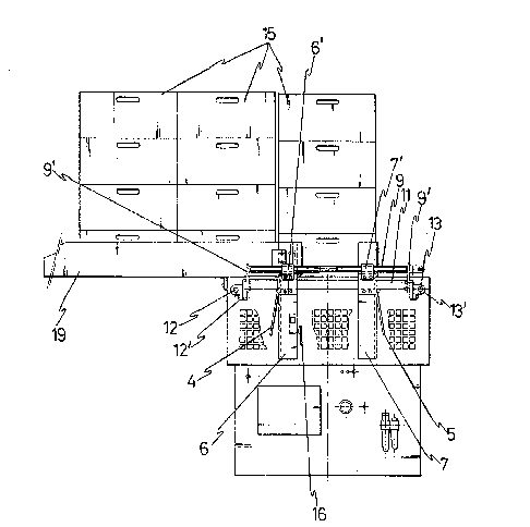
Figure 1.- This shows an elevation projection of the box
stacker which is object of this invention, and it includes a
conveyor belt which leads each of the boxes up to the actual
stack itself.
Figure 2.- This is a profile view of the box stacker, where

several rows of automatically stacked boxes are shown.
Figure 3.- This is a perspective view of the main zone of
the stacker of the invention, which is where each row of boxes
are formed.
DESCRIPTION OF THE PREFERRED FORM OF EXECUTION
Referring to the numeration adopted in the figures, the
stacker of boxes of the invention is associated with a box
shaping machine. At the bottom of this machine, the boxes emerge
and fall by gravity, and advantageously slip down a slide (1),
on a conveyor belt (2) which embodies the novelty of having side
positioning plates (3). Each box is then carried to one end of
the conveyor belt where the stacker of the actual invention is
found.
It has easily adjustable upright corners or guides, two in
front (4 and 5) and two at the rear (6 and 7), which correspond
to the upright corners of the boxes, and at the same time they
are fixed to some runners (4', 5', 6' and 7') which are screwed
parallel to two cross screws (8 and 9), which are coupled to some
small front end supports (8') and rear end supports (9'), which
are solidary to cross bridges (lO and 11) respectively, which are
in turn connected to two longitudinal screws (12 and 13) by means
of small end supports (12' and 13'). With this layout, when the
respective screws turn one way or the other, the vertical guides
are brought close or separated, and are adjusted to suit the
dimensions of the box. When each of these lies b~tween the four
upright guides, a pusher (14) emerges from the top of the lower
part, which moves the corresponding box at the bottom, to a pre-
fixed height where it will later be kept in this stable position.
This pusher (14) will then come down to its resting place, when
another box can then be fitted between the four upright guides,
which will also be lifted up in the same way as the previous one
and it will be moved to an upper position pushed by the second
box, which will occupy the place of the first box. Following
this continuous process, a group or row of stacks will be formed
(15) which will automatically be counted at the end of each run
(16). This group of boxes (15) will be moved in a direction that

is perpendicular to the conveyor belt (2) by means of a
horizontal pusher (17) which is move.d by a cylinder (18), which
preferably will be a pneumatic one and suitably driven by a guide
at the front cross bridge (10), where the pneumatic cylinder is
also fitted.
The movement of each row of boxes (15) once formed, is made
automatically so as to form another one. To do so, one of the
front guides (4) and another rear one (6) on the same side, each
have upper plates or strips (19) which face one another and
permit the seating of various groups of aligned stacks (15). The
upright guides (4 and 5) which are connected to the front bridge
(10) moreover embody lower prolongations (20) (details shown in
figure 1) which fit on and are driven along rails or side guides
(21), which are connected at one end to small supports (22) of
the conveyor belt (2), whereas at the other ends, they are linked
to the rear vertical guides (6 and 7). In this way, each box
that comes off the conveyor belt (2) is perfectly driven as soon
as it enters the stacking zone.
Along the conveyor belt (2) and on either side of it, two
rods have been designed (23) so that the boxes are perfectly
aligned on their run along it (2) and these rods are connected
to small supports (22) and to other (22') similar ones, all
established on either side of the conveyor belt.

Dessin représentatif
Une figure unique qui représente un dessin illustrant l'invention.
États administratifs

2024-08-01 : Dans le cadre de la transition vers les Brevets de nouvelle génération (BNG), la base de données sur les brevets canadiens (BDBC) contient désormais un Historique d'événement plus détaillé, qui reproduit le Journal des événements de notre nouvelle solution interne.

Veuillez noter que les événements débutant par « Inactive : » se réfèrent à des événements qui ne sont plus utilisés dans notre nouvelle solution interne.

Pour une meilleure compréhension de l'état de la demande ou brevet qui figure sur cette page, la rubrique Mise en garde , et les descriptions de Brevet , Historique d'événement , Taxes périodiques et Historique des paiements devraient être consultées.

Historique d'événement

Description Date
Inactive : CIB désactivée 2017-09-16
Inactive : Symbole CIB 1re pos de SCB 2017-01-07
Inactive : CIB du SCB 2017-01-07
Inactive : CIB expirée 2017-01-01
Inactive : CIB de MCD 2006-03-11
Demande non rétablie avant l'échéance 1997-11-10
Le délai pour l'annulation est expiré 1997-11-10
Réputée abandonnée - omission de répondre à un avis sur les taxes pour le maintien en état 1996-11-11
Demande publiée (accessible au public) 1994-01-15

Historique d'abandonnement

Date d'abandonnement Raison Date de rétablissement
1996-11-11
Titulaires au dossier

Les titulaires actuels et antérieures au dossier sont affichés en ordre alphabétique.

Titulaires actuels au dossier
BOIX MAQUINARIA, S.A.
Titulaires antérieures au dossier
JOSE BOIX JAEN
Les propriétaires antérieurs qui ne figurent pas dans la liste des « Propriétaires au dossier » apparaîtront dans d'autres documents au dossier.
Documents

Pour visionner les fichiers sélectionnés, entrer le code reCAPTCHA :


Pour visualiser une image, cliquer sur un lien dans la colonne description du document (Temporairement non-disponible). Pour télécharger l'image (les images), cliquer l'une ou plusieurs cases à cocher dans la première colonne et ensuite cliquer sur le bouton "Télécharger sélection en format PDF (archive Zip)" ou le bouton "Télécharger sélection (en un fichier PDF fusionné)".

Liste des documents de brevet publiés et non publiés sur la BDBC .

Si vous avez des difficultés à accéder au contenu, veuillez communiquer avec le Centre de services à la clientèle au 1-866-997-1936, ou envoyer un courriel au Centre de service à la clientèle de l'OPIC.

({010=Tous les documents, 020=Au moment du dépôt, 030=Au moment de la mise à la disponibilité du public, 040=À la délivrance, 050=Examen, 060=Correspondance reçue, 070=Divers, 080=Correspondance envoyée, 090=Paiement})


Description du
Document 
Date
(aaaa-mm-jj) 
Nombre de pages   Taille de l'image (Ko) 
Revendications 1994-01-14 1 40
Dessins 1994-01-14 3 68
Abrégé 1994-01-14 1 23
Description 1994-01-14 4 160
Dessin représentatif 1998-08-16 1 18
Taxes 1995-10-01 1 58
Taxes 1994-09-29 1 54