Note: Descriptions are shown in the official language in which they were submitted.
V~og~ 08 2081>2~
r~U~ T~IENT G~O~T~ CUTTU~ING SYSTE~ AND A ~TH0~ ~r u
Field of the Invention
This invention relates generally to
microorganism culturing and identification, and more
specifically to a Multi-Nutrient Growth Culturing System and a
Method of Use.
Backqround of the Invention
The prior art is replete with disclosures o units
for the collection and growth of microorganisms from 2 liquid
sample.
A number of units include filter members used to trap
microorganisms present in the liquid sample, for subsequent
exposure to a solid or liquid media contained in a single
compartment. Representative patents disclosing such units are
U.S. Patent Nos. 4,82,005 (Friedman et al.), ~,i97,38'. (Gold-
man), 4,777,137 (Lemmonier), 2,879,207 and 2,923,569,
(Poitras), and 3,929,583 (Sharpe et al.).
In one embodiment of the Lemmonier '1~7 patenl a
sealing member covers the opening into a media-retaining
compartment of a container positioned below the filter member,
and a series of small openings about the perime_e~ of the
container, which are not covered by the sealing member, permits
the liquid of a sample to be tested to pass out of the device,
while microorganisms in the sample are trapped on the filter
member. Thereafter the sealing member is removed to permit a
nutrient therein to "feed" the microorganisms previously
deposited on the filter member.
A unit employing a pervious sheel to cultivate
microorganisms for subsequent exposure to different liquid
media containec in a segmented Petri dish is disclosed in U.S.
Patent No. 4,775,628 (~akakura et al.). In this device the
specimen (e.g., puss) containing the microorganisms to be
cultivated is applied to the pervious sheet ~ith a spiral
plater; no~ by being flowed onto and through a filter member to
rehydrate plural dehydrated media.
WO91/1808~ 2 0 8 2 6 ~ ~ PCT/i S9]/0~1()1
~ nits also have heen designed which :~ave seg~,en ed
media sections onto which a user directly applies a te.~ samplP
for gro;:th and testing. However, these units do not emplo~ a
filter membrane to collect microorganisms fo~- e~:posure Ic
multiple types of dehydrated media. Represen~al_ive paten_s
disclosing such units are U.S. Patent Nos. 3,102,0i32, (~re-.er`,
4,072,573 (Cady et al.), Design Patent No. 25~3,761 (C-raham),
3,912,~96 and ~,042,463 (Haque et al.), 4,076,591 (r:eden),
4,12,037 (Lemmonier), and 4,568,633 (Walton).
In addition, it is known in the art '_o utilize a
dehydrated media to culture microorganisms, whic}l ~av be
activated upon wetting, as lS disclosed in ~.S. Paten_ ~os.
4,485,171 (Ikeda et al.), ~,245,043 (Lund), ~,5~7,21,
(Malecki), 4,250,256 (Wielinger et al.).
Moreover, the use of a filter membrane to tra
microorganisms used in connection with a dried media also is
disclosed in ~.S. Patent ~os. 2,761,813 (Goetz), 4,~35,171
(Ikeda et al.), 2,677,646 (Lovell et al.), and 3,7~1,877
(Shaufus).
In spite of all the above teachings, however, i', is
believed that a need still exists for a single unit in which
microbes may be effectively collected and quickly filtered and
grown without the need to handle the filter membrane upon whic~
the sample is deposited, which is not susceptible to leakage or
dehydration of media during storage, handling and/or use, and
which, for at least certain applications (e.g., the testing of
urine) does not require the use of additional vacuum devices.
Obiects of the Invention
Accordingly, it is a general object of this invention
to provide a device which permits the user to quickly collect
and grow microorganisms in a liquid sample while minimizing the
dangers of contamination from outside sources.
It also is an object of this invention to permi. â
user to reliably subject collected microorganisms tc a number
of different dehydrated media.
~'091/18~ 2~82~ PCT/~S91/0~
It is a further object of this invention ~o effec-
tively collect microorganisms to be tested from a liq~lid sample
and which is not susceptible to leakage of the growth media or
the liquid sample during storage, handling and/or use.
It is a further object of this invention to permit
the user, in some applications (e.g., the testing of urine), to
quickly collect and grow microorganisms from a liquid sample
without the need to use capital intensive equipment, including
but not limited to expensive incubation and vacuum devices.
It is yet still a further object of this invention to
provide the user with a method of collecting and culturing
microorganisms which is easy to accomplish, fast and reliable.
It is still a further object of this invention to
reliably per~it a user to collect and grow microorganisms, for
the purpose of identification, and then to save or store the
cultured microorganisms for future reference and/or use.
It is still a further object of this invention to
effectively collect microorganisms from both large and small
liquid sample sizes, and, if necessary or desired, to permit a
vacuum assist to remove excess liquid.
Summary of the Invention
The above and other objects of this invention are
achieved by providing a device and method for culturing and
identifying microorganisms in a liquid sample. The device
includes a container having a transverse wall and a peripheral
skirt extending upwardly therefrom to define an internal
compartment, with the peripheral skirt terminating in an upper
surface to define an opening into the internal compartment. A
partition means in the internal compartment divides the
compartment into at least two sections, and a porous material
including a dry (dehydrated) nutrient is located in each of the
at least two sections. A filter member is contiguous to the
upper sur.ace of the peripheral skirt and overlies the at least
two sections of the internal compartment of the container, with
the lower surface of the filter member closely adjacent to, and
preferably in contact with the porous material including dry
WO 91/1808~ PCr/~S91/03~
2~82~3~
nutrient. The filter member has pores of a size fcr preventing
the microorganisms of the liquid sample fro: passing
therethrough while permitting the li~uid Oc _he liquid sample
to pass therethrough. The liquid sample is applied to he
upper filter surface to cause said sample to flow transverselv
along the upper surface of the filter member into overly~ng
relationship with the at least two sections of the compartment,
before passing completely through the filter member and into
the porous materials. The porous materials aid in pulling ~he
liquid of the liquid sample through the pores of the filte-
member by capillary action for rehydrating the nutrient, to
thereby permit the rehydrated nutrient to be directed th~ough
the filter member to the microorganisms.
In the preferred embodiment of the invention the
porous material including the dry nutrient is in the form of a
porous carrier having the dry nutrient retained therein.
Accordingly, in the preferred construction the porous structure
is of a defined geometric shape.
In the preferred embodiment the upper surfaces of ~he
peripheral skirt and partition means are in substantially the
same plane to effectively isolate the nutrients in each of the
sections of the container from each other.
In the preferred embodiment the device has a cover
with a liquid receiving means therein, to permit the introduc-
tion of liquid into the device. The cover preferably includes
a downwardly extending peripheral skirt providing a downwardly
facing surface contiguous to the upper surface of the
peripheral sXirt of the container. The filter member is
located between these latter two surfaces, and preferably is
bonded to one of them. Preferably one or more vents extend
through the partition means for the venting of the device.
Quite surprisingly it has been found that although
the filter member permits transverse flow o~ the liquid sample
applied to its upper surface, so that the liquid substantially
covers the upper surface of the filter before being absorbed
into each of the porous materials including dehydrated media,
the different media, which are rehydrated by the liquid, are
~'0 91/180~ PC~ 'S')l/0~
2082~ 2~
not subjected to this same transverse flow when transmitted
through the lower surface of the filter member into contact
with the microbes, even when the filter member has the same
properties th oughout its entire structure.
lhus, the transverse flow of the liquid sampie along
the filter media permits the microbes to be distributed ove~
the filter member into overlying relationship with each of the
different media. Moreover, this transverse flow of the liquid
sample permits the liquid to rehydrate the media, with the
assistance of capillary attraction. Although this transverse
flow is extremely important to the proper operation Of the
device, a corresponding transverse flow of the rehydrated
media, if it did occur, would cause an intermixing of the
different media on the filter member; resulting in decreased
efficiency of the system. Since significant transverse flow of
the rehydrated media does not take place in the filter member,
and is precluded by the partition means in the container from
ta~ing place within the container, the present invention has
proven to be successful in exposing microbes to selective
and/or differential media in discrete, selected areas of a
filter member overlying each of the media, for the purposes of
~uickly and efficiently culturing and identifying such
microbes.
Descri~tion of the Drawinqs
Other objects and many attendant features of this
invention will become readily appreciated as the same becomes
better understood by reference to the following detailed
description when considered in connection with the accompanying
drawings wherein:
Fig. 1 is a isometric view of a culturing system in
accordance with this invention;
Fig. 2 is a exploded isometric view of the culturing
system sho-~n in Fig. l;
Fig. 3 is a sectional view taken along line 3-3 of
Fig. 2; and
'VO g]/]8(!8~ PC!/I`S~l/0~
6 2~82~3~
~ ig. 4 is a sectional view taken alor.c line 4-~. of
Fig. 3.
_tailed Descri~tion of the Preferred Embodiments
Referring now to various figures of ~he drawings
where like reference numerals refer to like parts there is
shown at 10 in Fig. 1, a device constructed in accordance with
this invention for use in culturing and identifying
microorganisms in a liquid sample.
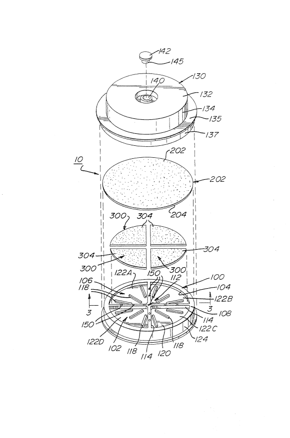
As shown most clearly in Fig. 2, the device comp-ises
a container 100, and a filter member 200 disposed above porous
carriers 300, with each of said carriers containing at least
one dehydrated media therein. In the most preferred
embodiment, the device 10 also comprises a cover 130 with a
liquid receiving aperture 140 therein.
As shown in Figs 2 and 3, the container 100 has a
transverse wall 102 and a peripheral skirt 104 extending
upwardly therefrom, to define an internal compartment 106. The
peripheral skirt 104 terminates in an upper surface 108 to
define an opening into the internal compartment 106. The
compartment 106 has partition means 112 extending upwardly from
upper surface 120 of the transverse wall 102 for dividing the
compartment 106 into separate sections. In the preferred
embodimen~ the partition means 112 are in the form of a pair of
raised dividers 114 which intersect at the central axis 116 of
the container to divide the compartment 106 into four separate
sections 122A to 122D. However, it is within the scope of this
invention to vary the number and geometry of the dividers 114,
to thereby vary the number and geometry of the separate
sections within the container 100. The dividers 112 provide
the important function of preventing the migration of media
between compartments, by separating the porous carriers 300
contained therein. Additionally, the device has in its most
preferred embodiment an outside wall 124 which is concentric
with peripheral skirt 104, for frictional engagemen_ with the
cover 130, as is more specifically descri~ed hereinafter.
`' ') 9 1 / 2 ~S08 ' l'CI'/ ~
7 2082~3~
Still referring to Figs. 2 and 3, a plu-a'it~ or -ibs
118 is provided on the upper surface 120 o~ transverse ~:all 102
within each of the sections 122A to 122D. These ri~s provide
open areas 123 between the porous carriers 300 and the upper
surface 120 of the transverse wall 102, when ~he c2~r iers 300
are disposed within the sections 122A-122D of the container
100. These open areas 123 constitute reservoirs bereath the
carriers 300 for any excess liquid which may not be retained in
the carriers during use of the device 10.
In addition, the ribs 118 maintain the porous
carriers 300 in their required position relative to the filter
member 200. Specifically, the height of the ribs is such that
when the porous carriers 300 are placed thereon, the porous
carriers are sufficiently close to the overlying fi'ter member
200, to permit the carriers to absorb liquid through the filter
member via capillary action. In the most preferred embodiment
of the invention the container 100 is molded as a unitary
member with the ribs 118 and raised dividers 114 there~n.
As shown most clearly in Figs. 3 and ~, a porous
carrier 300 is located in each of the sections 122A to 122C,
and each carrier has an upper surface 304 closely adjacen' the
upper surface 108 of the peripheral skirt 104. Each carrier
300 includes a dry nutrient or media therein, which is exposed
to any microorganisms present in the li~uid sample to be
investigated, in a manner to be described in detail
hereinafter. Additionally, the carriers 300 also may hold
inhibitory substances, such as antibiotics, antimicrobial
agents, etc., or any other substances which may affect
microorganism growth. Reference to "nutrient(s)" and/or
"media" throughout this application includes these inhibitory
substances, in addition to substances that promote the growth
of the microorganisms.
The carriers 300 in accordance with the preferred
embodiment of this invention preferably are made of any
suitable porous material for retaining the dehydrated nutrient
therein, and are capable of holding and retaining a volume of
the liquid sample to be investigated. ~his volume of the
~091/1808~ ~CT/~'591/0~
3 ~0~2~
liquid sample functions to activate (i.e., rehydrate) the
dehydrated media. Carriers made from materials such as nitro-
cellulose, and available from Sartorius GmbH, Gottingen, Fed.
Rep. of Germany, are preferred. However, other materials,
such as foam, may be utilized to form the carriers 300.
In accordance wi~h the method of this invention, as
described in detail hereinafter, a liquid sample, such as
water, urine, blood, soft drinks, etc., to be investigated, is
applied to and travels transversely over filter member 200,
before being drawn completely through the filter member via
capillary action, by the underlying porous carriers 300, to
thereby ac~ivate the dehydrated media in the carriers. The
sample is then incubated in the device lO for the requisite
time period, and thereafter, any resulting microorganism growth
or lac~. thereof, is analyzed.
In the preferred method of the invention the volume
of the liquid sample introduced into the device lO is matched
to the liquid retaining volume of the porous carriers, such
that the liquid passing through the filter member 200
preferably will be completely absorbed within the porous
carriers 300, without any excess (overflow) of the liquid
sample being present in the device lO. As an alternative, the
particular carriers utilized may be chosen to absorb or retain
a desired liquid sample size. This permits the user to vary
the liquid holding capacity of the carriers for applications of
use where larger or smaller liquid sample sizes are
advantageous, while still permitting the rehydrated nutrient(s)
to be directed to the filter member and the microorganisms
thereon.
For many medical applications, such as in the testing
of urine, only small liquid samples are required for use in the
device lO of this invention. In fact, as will be discussed in
greater detail hereinafter, applicant has obtained e~cellent
results in the testing of urine with liquid samples of appro~i-
mately only 3 mls.
However, in the testing of beverages, and for other
non-medical applications, it may be necessary to use larger
~ T'CT/lS91/0~]()~
9 ~2~
liquid volumes, on the o~der of 100 mls. ~.her. such larger
volumes are utilized it may be necessary to increase the size
of the individual carriers 300, so that they can retain more of
the liquid sample. Moreover, as will be explained in detai'
hereinafter, in accordance with one aspect OI this invention a
vacuum assist can be employed to remove excessive quantities of
liquid from the device.
As shown in Fig. 3, the filter member 200 has an
upper surface 202 for initially receiving the liquid sample
thereon, and a lower surface 204 which is contiguous to the
upper surface 108 of the peripheral skirt 104. The filter
member 200 is positioned to overly the various sec_ions 122~-
122D of the internal compartment 106 of the container 100, with
the lower surface 204 of the filter member 200 being closely
adjacent to, and preferably in engagement with the upper
surface 304 of each of the porous carriers 300. The filter
member 200 may rest on or be retained unsecured to the device
10, or alternatively may be bonded in place, as will be
described in detail below.
The filter member 200 has pores of a size for
preventing microorganisms of the liquid sample from passing
therethrough, while permitting the liquid of the liquid sample
to pass therethrough into the underlying pcrous carriers 300.
The type of filter member used in the device may vary depending
upon the particular applications of use, and suc~ filter
members are well known to people skilled in the art. Fo
example, in order to trap microorganisms suspected of being
present in a human urine sample, it is preferable to use a
cellulose nitrate membrane having a pore size of .45 ~m,
available from Sartorius GmbH, Gottingen, Fed. Rep. of Germany.
In the preferred embodiment of the invention the
filter member 200 causes the liquid sample, when applied to the
upper surface 202, to flow transversely along the filter membe-
into overlying relationship with the various sections 122A-122D
of the compartment 106, before completely passing throug~ the
filter member into the porous carriers 300. As stated earlier,
`~'091/1~08~ Pcr/ ~ ss l /0~1 (\ 1
20~2~
the porous carriers 300 assist in pullins the llqui sample
through the pores of the filter membe- 200 by capillary a-tlrac-
tion to rehydrate the media in each of the carriers. In the
most preferred embodiment of the invention the upper surface
30~. of each of the carriers 300 is in contact witn the filter
member lower surface 204, which enhances the capillary
attraction for the liquid and also permits the rehydrated mediz
to be directed to the microorgan sms which may be trapped on
the upper surface of the filter member 200, afte~ the liquid
sample has been directed into the device 10.
In order to fully rehydrate the nutrient(s) in the
carriers 300, while preventing or minimizing the li~elihood of
fluid leakage, it is preferable that the volume of the liquid
sample be approximately the same as, or only slightly less than
the liquid holding capacity of the carriers 300. In an
exemplary embodimen~ of the inven-ion, in which the liquid
sample is urine, approximately 3.0 milliliters (mls) of the
urine is directed into the device 10 having four carriers 300,
and each of said carriers has the capability cf retaining,
without lea~age, approximately 0.75 mls.
The use of a filter member 200, in conjunction "ith
carriers 300 which absorb the liquid of the sample to be
investigated is extremely advantageous. One advantage in
utilizing a filter member to trap and isolate microorganisms on
its upper surface, and then exposing the filter member to a
media, is that the filter member is able to collect a larger
numbe- of microorganisms (almost 100% of those contained in the
liquid sample) in a small, defined surface area. Upon
incubation, these microorganisms are much easier to identify as
colonies, due to their higher initial concentration on the
filter, as opposed to the concentration achieved when the
microorganisms are spread over a wide surface area, such as
when being inoculated on a conventional agar plate with a wire
loop. Due to this higher initial concentration of
microorganisms on the filter member 200, it ta~es much less
time for the microorganisms to grow to detectable colonies.
Anothe- factor which enhances the growth rate of the colonies,
'- 9~/1808' PC~t~ l/0:~1() '
2~2~3/~
11
at least in some applications, is that gro;.th inhibito~s
initially present in the liquid sample also are ~irecte~
through the filter member 200, to separate the inhibitors from
the microbes.
In order to properly identify microorganisms grown on
a conven~ional agar plate, the inoculated plate must usually be
incubated for approximately 24 to 48 hours and more. In
contrast, the current device and method permits rapid isolation
and identification of colonies in as little as ~. hours. For
example, using the device and method of the above invention
with a test sample of approximately 3.0 milliliters o~ urine,
when incubated with as little as 300 to 3,000 E.coli cells/ml,
colonies were visible at 4 hours, countable bv 8 hours and were
confluent (complete lawn of bacteria) on the filter member 200
in 10 hours. A presumptive diagnosis generally can be made in
-10 hours when the device 10 is used with a different
dehydrated media in each of the sections 122A-122D. A
significant advantage of this invention is that it permits a
rapid diagnosis of a bacterial infection to be made, to thereby
permit a physician to begin treatment to control and/or
eradicate the infecting agent much more quickly than .ith the
use of prior art culturing systems. For example, in order for
a typical diagnosis to be made utilizing some of the prior art
devices and methods, an inoculum typically requires at least
100,000 bacteria cells/ml and requires 24 to 48 hours for
detection and analysis.
As shown in Figs. 2 and 3, in the preferred
embodiment the device 10 additionally comprises a cover 130
having a top wall 132, a downwardly extending peripheral skirt
134, and a liquid receiving aperture 140 extending through the
top wall for permitting the introduction of liquid sample into
the device. The peripheral skirt 134 has a transversely
extending intermediate section 135 which provides a downwardly
facing, annular surface 136 contiguous to the upper surface 10~
of the container 100. In addition the skirt 134 has a
downwardly extending lower section 137 for frictional
engagement with the outside wall 124 of an outer peripheral
~o s~ ns~ Pcr/~,ssl/Q~ln-~
12 2~2~
skirt of the container 100. The cover 130 preferably is made
of clear plastic, and, if desired, may also additiona ly
comprise a clear magnifying section (not shown), whlch permits
the user to easily view smaller colonies.
In the preferred embodiment the filter member 200 is
bonded to the downwardly facing surface 136 of the cove-.
However, it is within the scope of this invention to merely
clamp the filter member in proper posi~ion within the device,
between the surfaces 136, 108. In either event the filter
member 200, with the microbes cultured thereon, can be removed
from the device 10 and retained as part of a patient's medical
record, or otherwise stored. This is an extremelv beneficial
feature of the present invention.
Referring to Figs. 2 and 3, the liquid receiving
aperture 140 preferably includes a removable plug 1~2 therein
to provide a sealed, breathable environment, and the plug may
be removed (see Fig. 2) to permit the sample to be introduced
into the device 10. As can be seen in the drawings, the inner
surface defining the aperture 1~0 is provided with a pair of
diametrically opposed, axially extending recesses 143 therein
to provide small air passages through which vapors can escape
from within the device, when a lower sealing section 1~5 of the
plug is within said aperture. This mini~,izes undesired
condensation of vapors on the cover 130.
In an alternative embodiment the plug 142 is
permanently secured to the aperture 140, and is comprised of a
material, such as rubber, or latex, which permits the entry and
removal of a syringe or other dispensing instrument (not shown)
to deliver the liquid sample to the filter member 200 for
testing, without re~uiring removal of the cover 130. The same
arrangement of ribs 145 can be provided in this embodiment, fo-
the same purpose of minimizing undesired condensation of vapors
on the cover 130.
As shown in Figs 2 and 4, the device 10 additionally
comprises one or more vents 150 which permits venting of the
device, for a number of purposes. First, the vent(s) permit
removal of any air present in the device when the liquid sample
` ~91/1~08~ r/~.~s~
13 208~ 4
is introduced. Second, these vents 150 also permit the
e~change of gases such as oxygen, etc. which ma~ be necessary
for the growth of aerobic organisms, while r,inimizing the
possibility of contaminating the device. Third, Ihese vent,
150 can be used with a vacuum assist to remove excess liquid
from the device lO, when needed or desired.
As can be seen best in Figs. 2-4, in ~he preferred
embodiment the vents 150 comprise channels or passages which
extend vertically through the dividers 114 of the container
lO0. In the illustrated embodiment one vent 5C is provided at
the central axis 116 of said container, and two other vents are
equally spaced-apart along each of the four "spokes" of the
dividers 114. The number and orientation of the vents 50 may
be varied. However, when it is anticipated that a vacuum
assist will be required or desired, for removing excess liquid
from the device, it is preferred that a plu-ality of vents be
provided along the dividers 114, as is shown in Figs. 2 and 4.
This arrangement permits a substantially uniform suction erfect
to be created along the lower surface of the filter member 200,
to thereby remove any pools of excess liquid from both above
the filter member 200 and from between the filter member and
carriers 300.
The carriers 300 in the sections 122A-122D may hold
one or a number of different dehydrated media, depending upon
the desired use of the device lO. For example, in attempting
to determine the presence and identity of microorganisms in
urine, four different types of media have been employed to
selectively cultivate microorganisms commonlv found in urine.
After cultivation, the types of microorganisms present in the
liquid sample were identifiable, based on the different growth
characteristics exhibited on the sections of 'he fil'er member
200 overlying the various selective and/or differential media,
in comparison with conventional standardized growth data.
Dehydrated media are extremely advantageous in the
above application because their use permits the device and
media to be completely sealed and stored for years until use,
without refrigeration or any special handling. Moreove~, the
`~'091/1X0~ J~
14 2082~
possibility that ~he media ~"ill break do;;n c. becor,e
contamina-ted is signlficantly reduced when the devic~ l0 ~ 5
properly aseptically sealed. The device l0 also is more easily
transported when dehydrated media are used because the chances
of spilling and/or contamination are also signi icantly
reduced. These advantages permit use s such as fie'd testers,
technicians, etc. to transport the device to ~he locatior. where
a sample is to be taken, if desired, and permits the sample 'o
be brought back in the device for growth and analysis.
Various types of dehydrated media which may be used
in conjunction with human urine testing include, but are not
limited to, ENDO, CASO, TERGITOL TTC, TEEPOL, CHAPI~.A1~ FC,
SABAURA7JD and CETRIMIDE available from Sartorius GmbH,
Gottingen, Fed. Rep. of Germany. Additionally, the same media,
but in different concentrations may be used in the sections
l22A-l22D.
The media commonly known as ENDO, is used to isolate
gram negative organisms such as Escherichia coli and other
coliforms. These organisms generally form colonies which
appear dark red with a greenish me_allic sheen when qrown in
the presence of ENDO. ENDO is slightly selective based on the
fermentation of lactose in the presence of basic fuchsin which
suppresses the growth of gram positive organisms. EN~o
conforms .o the American Public Health Association Standards,
American Public Health Association, h7ashington, DC (l~th Ed.
1975)-
CASO is a selective media for the detection ofsta~h~lococci, such as staphYlococcus aureus, which yields
yellow colonies when used with appro~imately 7.5% sodium
chloride (NaCl), by volume, as a wetting agent, or with the
addition of phenylethyl alcohol as in Trip Soy Agar with sheep
blood. CASO may also be used for the growth of fastidious
pathogenic organisms more likely found in blood than in urine
by adding approximately 10% serum, by volume. CASO also
inhibits the spread of 7?roteus species. _aphYlococci may
alternatively be grown and isolated in the presence of phenyl-
ethyl agar or CNA media (Columbia Co.).
~9l/180~
~082~
TERGITOL TTC is a selective and differen ial media
for the isolation of coliforms, inhibiting gram positive
behavior and the spread of the proteus species. Escherichia
coli colonies and aerobacter can reduce TTC and hence appear
orange to yellow when grown in the presence of TE~GI~OL TI~C,
while coliforms appear red in color. TERGITOL TTC also
resembles Simmons Citrate media conventionally used to
differential coliforms. G.H. Chapman, Superior Culture Media
for the Enumeration and Differentiation o' Coliforms, Journal
Bacteria, 53:50~ (1947).
TEEPOL media is similar to TERGITOL TTC and is used
for the isolation of E.coli and fecal coliforms. When grown in
the presence of TEEPOL, E.coli colonies appear yellcw, while
colonies of non-lactose fermenting organisms appear dar}; red in
color.
CHAPMAN media is a mannitol-sodium chloride-phenol
red medium for use in detecting pathogenic staphylococci in
foods and other materials. Staphylococcus aureus develops
golden vellow to orange-colored colonies with a yellow zone
(mannitol-positive). Staphyloccoccus epidermidis forms whitish
colonies without changing color.
M-FC media is employed for the detection of E.coli
and fecal coliform bacteria. E.coli and fecal coliform forms
blue colonies with diameters of 1-2 mm.
SABOURAUD media is employed for culturing yeasts,
molds, acid-tolerant and acidophilic bacteria, and also for
detecting yeasts and molds in beverages, such as fruit juices
and for sterility testing of pharmaceuticals and for isolating
dermatophathogenic yeasts and fungi. Yeasts usually develop
smooth white or colored colonies. Molds generally form velvety
or fluffy, cotton-like colonies in the early growth phase, and
may take on various colors after conidiospore production.
CETRIMIDE is a media which permits the isolation and
presumptive identification of pseudomonas aeruqirosa, whose
colonies appear as a greenish color when grown in its presence.
This type of media inhibits the growth of almost all other
organisms.
g l / ~ ~308 ' PCr/ ~
~Q~2~
16
It is preferable that the device 10 be pre-pacXaged
to include the carriers 300 with the differenl~ types of
dehydrated media to be used in the investigation, to Imini~i7e
potential contamination. However, it should be apparen. tna~
the carriers with dehydrated media therein may be inserted
before the liquid sample is applied to the device '0, by
removing the cover 130 and the filter mem~er 200 (which may be
secured to the cover) and inserting the desired dehydrated
media cor.'aining carriers 300 into sections 122A-i22D of the
container 100.
In an exemplary embodiment of this invention a liquid
sample of human urine, having an approximate volume of 3.0 mls,
is directed into the container 100, on the upper surface 202 or
filter member 200. As the liquid is applied to the upper
surface of the filter member it travels transversely ac-oss the
filter member 200, substantially uniformly in all directions,
to substantially cover the upper surface of the filter member,
before any significan_ quantity of the liquid passes through
the filter member. Therefore, by first flowing transversely
along the filter member 200, substantially equal volumes of
urine are p- -~ over each of the carriers 300. Thereafter,
the liauid is Glrected downwardly through the filte~ mem~er 20G
towards and into each of the underlying dehydrated porous
carriers 300 in the sections 122A-122D. The downward movement
of the liquid sample through the filter member is enhanced by
capillary action provided by the carriers 300. As the li3ui d
(e.g., urine) enters the carriers 300 it activates the various
dehydrated media, and the media is thereafter directed through
the filter membrane to any microorganism trapped on the upper
surface thereof. Moreover, each of the carriers has a liquid
holding capacity of appro~imately 0.75 mls., and therefore the
four carriers 300 are capable of retaining virtually all of the
3.0 mls. of the liquid sample directed through the filter
member 200. This substantially eliminates the presence of free
liqlid in the device 10, which, if present, could leaX from the
device 10 during handling.
~ 91/1808' PCT/~91/031()~
17 ~2~34
Thereafter, the inoculate~ device is incubated at
37DC for approximately 4-lO hours. Analysis of any resultan~
microorganism growth may then readily be undertaken by
comparing the microorganism colonies grown in a specific media
with conventional standardized data.
As stated earlier, when larger liquid samples are
employed with the device lO, e.g., on the order of lO0 mls. for
the testing of beverages, it may be necessary or desirable to
utilize a vacuum assist to remove excess quantities of liquid
from the device. In such a case the container lO0 can be
placed on a suitable vacuum device (not shown), and a suction
applied through the various vents 150 extending through the
dividers 114. This vacuum assist will act to direct excess
liquid located above the filter and/or in the region between
the carriers 300 and the lower surface of the filter 200, out
of the device lO, to minlmize the possibility of undesired
fluid leakage from the device.
Without further elaboration the foregoing will so
fully illustrate my invention that others may, by applying
current or future knowledge, readily adapt the same for use
under various conditions of service.