Note: Descriptions are shown in the official language in which they were submitted.
2082720
C-840
ADJUSTABLE RIGHT ANGLE TRANSFER DEVICE
FOR CONVEYING FLAT ARTICLES IN ONE OF TWO DIRECTIONS
Field of Invention
This present invention relates generally to a method
and apparatus for changing the direction of motion of flat
articles, and in particular to method and apparatus for
changing the direction of motion of mailpieces in an
inserter machine.
Background of the Invention
Devices are known which turn flat articles, such as
letter envelopes, within a plane. These devices are
required where envelopes are discharged from an inserter and
are not properly oriented to be fed to a downstream device
such as.a franking machine. An inserter is a machine that
inserts selected items in an envelope for further
processing. The filled envelope is sealed and then conveyed
to a franking machine to have postage imprinted thereon.
Generally, turner devices have the disadvantage of having to
be an integral part of the inserting machine.
Examples of devices which turn flat articles in
inserting machines are shown in U.S. Patent No. 4,726,461
issued February 23, 1988 to J. Pokrinchak and U.S. Patent
No. 4,928,807 issued May 29, 1990 to D. Auerbach, both of
which patents are assigned to the assignee of the present
invention.
It is known to change the direction of travel for
flat articles without changing the orientation of the
articles, i.e., without rotating or turning the articles.
It is also known that for a one stage right angle change in
direction the articles must be stopped in one direction
before being conveyed in the right angled direction. Such a
device is described in U.S. Patent No. 4,909,374 issued
2~~~~2~
- 2 -
March 20, 1990 to M. Skrypalle and assigned to the assignee
of the present invention.
It is also known that a right angle change of
direction for flat articles can be achieved in two or more
stages by the use of deflection rollers which change the
direction of travel by forty-five degrees (45°) or less at
each stage. Such an apparatus and method used in a sorting
machine is disclosed in U.S. Patent No. 4,527,792 issued
July 9, 1985 to G. Burkhardt. The Burkhardt apparatus has
several limitations which prevent it from being useable in
an inserting machine. The apparatus is limited to changing
the direction of travel from a path parallel to a long edge
of the mailpiece to a path of travel parallel to the short
edge thereof. Furthermore, for all sized mailpieces, the
Burkhardt apparatus requires a side-justified line of travel
along the first direction of travel so that the deflection
rollers can engage the article at the right moment to
achieve an accurate change in direction. Typically, in an
inserter, the center line of travel of the mailpiece is
fixed with the side guides being adjustable for handling
various sized mailpieces.
Several improvements in the throughput of various
upstream modules (such as feeders, accumulators and insert
stations) have raised the expectation that the output of the
inserting machine will keep up with such improvements.
However, when the outgut is increased on inserters which
include conventional turner devices, the turner devices are
not maintaining the increased output rate. The turner
devices are experiencing various problems when they are
operated at higher speeds. For example, inserts are flying
out of envelopes before the flap can be closed and turner
components are malfunctioning.
Tn Canadian Patent Application Serial No. 2,054,515
filed on October 30, 1991 and assigned to the assignee of
the present invention, a method and apparatus is disclosed
for changing the direction of motion of flat articles being
conveyed along a first path to a second path. The apparatus
_2082~2p
- 3 -
includes a deck having a first side for receiving an article
from a first direction and a second side for conveying the
article in a second direction which forms an acute angle
equal to or less than forty-five degrees (45°) with the
first direction. There is a structure which includes a
plurality of angled roller pairs for conveying the article
aver the deck in the second direction. The conveying
structure engages a leading edge of the article only after
the article has been disengaged by a conveying structure in
the first direction. There is a registration wall
positioned downstream from the second direction conveying
structure adjacent a third side of the deck. The
registration wall extends a third direction whereby the
registration wall is at a right angle to the first
direction, wherein the leading edge of the article is driven
against the registration wall after the article has been
disengaged by the second direction conveying structure.
There is a structure for conveying the article in the third
direction after the article is against said registration
wall.
In Canadian Patent Application Serial No. 2,074,023,
filed on July 16, 1992 and assigned to the assignee of the
present invention, a method and apparatus is disclosed for
aligning while changing the direction of motion of flat
articles being conveyed along a first path to a second path.
The apparatus includes an adjustable registration wall in
combination with an angled roller assembly that perform the
dual function of conveying the article in the third
direction and aligning the article against the registration
wall. This apparatus solved registration problems, such as
the article crashing into the registration wall and
rebounding away from the wall while being conveyed at high
speed in the third direction.
Summary of the Invention
~~~~720
- 4 -
It has been found that the foregoing apparatus and
methods for changing the direction of motion of a flat
article can be configured in an assembly wherein one
adjustable configuration can be used to change direction
ninety degrees to the left or right of the original
direction of motion of the article.
In accordance with the present invention, an
apparatus is provided for changing the direction of travel
of a flat article being conveyed in a first direction to one
of two other directions without changing the orientation of
the article. The apparatus comprises a circular deck
mounted on a frame. The deck is pivotable along a center
axis of the deck between a left position and a right
position. There is structure operatively coupled to the
deck for conveying the article over the deck, the deck
conveying structure having a first end and a second end,
wherein, when the deck is in the left position, the deck
conveying structure receives the article being conveyed in
the first direction at the first end and conveys the article
in a second direction of forty-five degrees (45°) to the
left of the first direction, and wherein, when the deck is
in the right position, the deck conveying structure receives
the article being conveyed in the first direction at the
second end and conveys the article in a third direction of
forty-five degrees (45°) to the right of the first
direction.
The apparatus further comprises a left alignment
assembly including a left registration wall situated
adjacent the deck at a location corresponding to the second
end of the deck conveying means when the deck is in the left
position. The left registration wall extends a fourth
direction at a right angle to the left of the first
direction. There are means for conveying the article in the
fourth direction after the article is against the left
registration wall. A right alignment assembly includes a
right registration wall situated adjacent the deck at a
location corresponding to the first end of the deck
~0~~~2~
- 5 -
conveying means when the deck is in the right position. The
right registration wall extends a fifth direction at a right
angle to the right of the first direction. There are means
for conveying the article in the fifth direction after the
article is against the registration wall, wherein the
leading edge of the article is driven against a respective
one of the registration walls after the article has been
disengaged by the deck conveying means.
Brief Description of the Drawincts
A complete understanding of the present invention
maybe obtained from the following detailed description of
the preferred embodiment thereof, when taken in conjunction
with the accompanying drawings wherein like reference
numerals designate similar elements in the various figures,
and in which
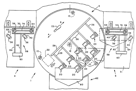
Fig. 1 is a plan view of a ninety degree take away
assembly connected in accordance with the present invention
configured to change the direction of travel to the left;
Fig. 2 is a plan view of the take away assembly in
Fig. 1 configured to change the direction of travel to the
right.
Fig. 3 is a side view of the take away assembly in
Fig. 1 taken along lines 3-3.
Description of the Preferred Embodiment
Referring now to the Figures, there is shown a
pivotable ninety degree transfer assembly, generally
designated 1, that includes a bidirectional forty five
degree take away unit, generally designated 2, and two
alignment apparatus, generally designated 4 and 6. Take
away unit 2 includes a circular deck 14 that is pivotably
situated at an elevated position above a lower frame 8.
Deck 14 is supported in the elevated position by three legs
members 10 that are equally spaced from one another around
2Q~~7~fl
- 6 -
the periphery of deck 14. There is a center pivot shaft 12
affixed to the center of the underside of deck 14 and
pivotably extending through a hub 13 bolted to lower frame
8. Leg members 10 include casters 11 which facilitate the
pivoting of deck 14 about center pivot shaft 12. Leg
members 10 and center pivot shaft are secured to the
underside of deck 14 in a known manner, for example by
recessed screws, so as not to interfere with the material
being conveyed on deck 14.
Take away unit 2 includes a roller conveying
arrangement comprising eight pairs of driven and idler
rollers for conveying envelopes 80 away from insert station
82. Deck 14 includes eight rectangular slots 18 each having
projected in part from below deck 14 a continuously driven
roller 16 above which an idler roller assembly 20 is
suspended. Below deck 14, there is a motor 22 mounted to
the underside of deck 14 so as not to interfere with the
pivoting motion of deck 14 or with the material being
conveyed on deck 14. Motor 22 is part of a conventional
shaft and pulley drive system, generally designated 24, for
driving driven rollers 16. In the preferred embodiment of
the present invention, motor 22 is a conventional variable
speed D.C. motor whereby the speed of driven rollers 16 can
be adjusted to optimize the throughput of take away unit 2
relative to the speed of other modules in the inserting
machine.
Above deck 14 are eight idler roller assemblies 20
positioned respectively above driven rollers 16. Each idler
roller assembly 20 includes a supporting shaft 26 fixedly
mounted at one end to the plate 28, which is secured to deck
14, and at the other end to plate 29 for supporting idler
roller assembly 20. Plate 29 is supported by shafts 26 and
is suspended above deck 14. A more detailed description of
the roller conveying arrangement of take away unit 2 is
provided in Canadian Patent Application Serial No.
2,054,525, filed on October 30, 1991 and assigned to the
CA 02082720 2002-10-15
assignee of the present invention.
There is a switch 23 mounted on the surface of deck 14. Switch 23 is connected
to
motor 22 to control the polarity of motor 22. When switch 23 is in position
"A", as seen in Fig.
1, driven rollers 16 rotate in the direction of arrow A. When switch 23 is in
position "B", as
seen in Fig. 2, driven rollers 16 convey rotate in the direction of arrow B.
The following description of alignment apparatus 4 applies also for alignment
apparatus
6 which is a mirror image of apparatus 4. Alignment apparatus 4 includes a
registration wall
30 adjustably mounted to deck 31. There are four driven rollers 32, 34, 36 and
38 which are
located below deck 31 and which are proj ected in part through four
rectangular slots 40 in deck
31. Below deck 31, there is a conventional drive system, similar to drive
system 24, which
includes motor 42, preferably of a variable speed type, and a conventional
belt and pulley
configuration for driving rollers 32, 34, 36 and 38.
Rollers 32, 34, 36 and 38 are angled 45 ° towards registration wall 30
for conveying the
envelope 26 in two directions, i.e., towards the registration wall 30 and
towards the downstream
device (not shown), for example, a device for sealing envelope 26. The angle
of rollers 32, 34,
36 and 3 8 matches the angle of the driven rollers of take away unit 2 to
prevent any unnecessary
skewing of the envelope as it passes from the control of take away unit 2 to
alignment apparatus
4.
Normal force is applied to rollers 32 and 34 by a pair of free floating roller
balls 54 and
2 0 56 each of which is suspended in a roller ball retaining assembly
generally designated 58.
Roller ball retaining assembly 58 includes a mounting block 60 rigidly
connected to deck 31
opposite registration wall 30. Two rigid shafts 62 and 64, for example, thick
steel shafts, are
rigidly mounted at one end to mounting block 60, and at the other end to a
suspending plate 66,
whereby suspending plate 66 is cantilevered over rollers 32 and 34. Suspending
plate 66 has
2 5 two apertures through which a pair of cups (not shown) are inserted for
holding free floating
roller balls 54 and 56. Each cup has an upper rim which sits on plate 66.
There are a pair of
caps (not shown) which fit into the cups and rest over roller balls 54 and 56.
A leaf spring 74
is secured to the center of plate 66 by a pair of screws and each end of leaf
spring 74 sits on one
of the caps. Each cap is slotted for receiving an end of leaf spring 74. Leaf
spring 74 applies
3 0 a force against the caps, which in turn apply pressure to roller balls 54
and 56. Roller balls 54
and 56,
CA 02082720 2002-10-15
cups and caps can easily be replaced by lifting the respective end of leaf
spring 74 to remove the
cap, cup and ball. Roller balls 54 and 56 rotate in any direction and do not
impede the sudden
change in direction when the envelope hits registration wall 30. The cups,
caps and balls are
made of light weight and wear resistant material that minimizes the normal
force applied against
rollers 32 and 34 and reduces the wear of roller balls 54 and 56 as they
rotate. A more detailed
description of the roller conveying arrangement of alignment apparatus 4 is
provided in
Canadian Patent Application Serial No. 2,074,023, filed on July 16, 1992 and
assigned to the
assignee of the present invention.
In operation, deck 14 is positioned in one of two positions. A right angle
transfer to the
left occurs when deck 14 is positioned, as shown in Fig. 1, with driven
rollers 16 situated
between insert station 82 and alignment apparatus 4. Switch 23 is in the A
position and driven
rollers 16 are rotating towards alignment apparatus 4. In this configuration
take away unit 2
conveys envelope 80 along a 45 ° path to alignment apparatus 4 which
completes the right angle
transfer. When envelope 80 enters the nip of roller 32 and roller ball 54, the
envelope is urged
against registration wall 30. Envelope 80 is then conveyed by rollers 32, 34,
36 and 38 along
registration wall 30. If
_g_
X082 X20
_ g _
envelope 80 enters the nip of roller 32 and roller ball 54
skewed, the envelope is quickly deskewed by rollers 32 and
34 urging envelope 80 against registration wall 30. The
normal force applied by roller balls 54 and 56 against
rollers 32 and 34 prevents envelope 80 from bouncing off the
wall. It will be understood that the combined effort of
rollers 32 and 34, roller balls 54 and 56, and registration
wall 30 provides a quick and lasting alignment of envelope
80 against registration wall 30.
A right angle transfer to the right occurs when deck
14 is positioned, as shown in Fig. 2, with driven rollers 16
situated between insert station 82 and alignment apparatus
6. Switch 23 is in the B position arid driven rollers 16 are
rotating towards alignment apparatus 6. In this
configuration, take away unit 2 conveys envelope 80 along a
45° path to alignment apparatus 6 which completes the right
angle transfer as previously described. It has been found
that the present invention works equally as well for the
right angle transfer of envelopes in either direction.
In the preferred embodiment of the present invention,
deck 14 is manually rotated about the axis of pivot shaft
12. Stops, such as blocks (not shown) mounted on frame 8,
axe used to stop the rotation of deck 14 at each of the
desired. positions. It will be understood by those skilled
in the art that the symmetrical arrangement of take away
unit 2 at the two positions with respect to the axis of
pivot shaft 12 promotes the bidirectional operation of take
away unit 2. Alternate methods of rotating deck 14 can be
used, such as, an electromechanical arrangement including a
servo motor to rotate deck 14 from one position to the
other. It has been found that it is unnecessary to lock
deck 14 in place once positioned, although a locking
mechanism can be used to ensure that deck 14 does not move
from alignment.
In the preferred embodiment of the present invention,
driven rollers 16 have a rubber surface, for example, a
urethane surface, and idler rollers 20 are aluminum with a
2082'20
- 10 -
crown surface. It has been found that take away unit 2
conveys envelopes of various dimensions and thickness in
both directions using such rollers comprising such surface.
Typically, the downstream apparatus (not shown) in an
inserter will have a registration wall which is adjustable
to handle different sized envelopes. Registration walls 30
of alignment apparatus 4 and 6 are adjustable for handling
different sized envelopes and for alignment with the
downstream registration walls.
While the present invention has been disclosed and
described with reference to a single embodiment thereof, it
will be apparent, as noted above t:~at variations and
modifications may be made therein. It is, thus, intended in
the following claims to cover each variation and
modification that falls within the true spirit and scope of
the present invention.