Note: Descriptions are shown in the official language in which they were submitted.
2 ~ 2 3
,
Karl H. Sengewald CimbH ~ Co. KG S 14327 DO/rg/gi/bp
Letterprcss printing method
;Ind applicator device for its implement~tion
The printing of web-like material such as paper, synthetics and the like is carried out by
means of an impression cylinder; the material is printed with a printing roller that is
inked via an inking system. During letterpress printing, the printing block on the printing
roller is provided with a raised design and, in the case of flexographic printing, the
pr;nting block consists of a synthetic material with elastomer properties. In letterpress
printing, particularly in flexographic printing, solvent-containing printing inks having a
solids content ot` approximately 30 wt.% and a solvent content of appro~cimately 70 wt.%
are used exclusively. In these processes, organic solvents and/or water are used as the
solvent (diluting agent).
Surprisingly, it has now been discovered that letterpress printing can be carried out with
solvent-free inks or binder systems (i.e. consisting entirely of solids) if a specially
designed pattern roller is used for inking or coating the printing or application roller.
The object of the present invention is therefore a method for applying binder systems,
particularly printing inks, to web material using the letterpress printing process, with the
binder system being applied to the letterpress form of an application roller by means of ~
pattern roller, characterized by the fact that a solvent-free binder system is applied with a
pattern roller having a cell pattern with a cell depth of ~ 15 !lm.
The object of the invention is also a printing device for implementing the above-
mentioned method, having an irnpression cylinder and one or more application rollers,
each cf which is supplied with a binder system, particularly printing ink, via a binder
application system with a pattern roller, characterized by the fact that the pattern roller
has a cell pattern with a cell depth of < 15 ~lm.
Finally, the object of the invention is a pattern roller with a cell pattern for implementing
the a~ove-mentioned method, characterized by the fact that the average cell depth is < lS
m.
'
~2~23
In general, all solvent-free binder systems that are characterized according to their
application properties as printing inks, paints or adhesives, for example, can be used for
implementing the method according to the invention.
Preferred solvent-free printing inks are radiation-cured inks, with UV-cured inks based
on acrylate, methacrylate or epoxy resin being preferred in particular. Such printing inks
are commercially available under the designation UVAFLEX ~Zeller & Grnelin GmbH,Eislingen), UYA-temp (Hostmann-Steinberg, Celle) or SUNCURE (Sun Chemical,
Brussels).
Examples of suitable solvent-free adhesives include radiation-curable hot-melt adhesives
based on acrylate, methacrylate or epoxy resin. These adhesives are used, for e~cample, in
the manufacture of compound foils.
The method according to the invention offers a number of advantages over known
flexographic printing methods which use solvent-containing printing inks having a
solvent content of 70 wt.%. Since traditional printing inks must release the solvent during
the course of drying, complex changes such as shrinkage, porosity, pigment changes or
"sepaMtion" of the binder inevitably occur. By comparison, solvent-free systems are
considerably more stable during the period between application and curing. At present,
only the shrink behavior of radiation-cured systems is known; in such systems, shrinkage
during curing can be minimized by means of a suitable molecular weight distribution.
Since the printing ink does not contain any solvent, it does not dry out, i.e. the thickness
of the wet film is the same as the thickness of the dry film. Since solvent does not escape,
there is no need for extraction measures or possible recovery of solvents, and solvent-free
printing inks are largely without odor; both of these &ctors considerably improve
ocGupational hygiene. Since no solvent evaporation occurs, special fire protection
measures are also unnecessary, and, fina}ly, the inks do not contain any raw materials
banned by the Gerrnan Federal Health Department or the Federal Drug Administration,
which is important for printing food packaging. The Draize value is less than 1, which
means that the skin irritation factor is equivalent to that of traditional inks containing
solvents.
Due to the use of solvent-free printing inks consisting entirely of solids, the final print
achieved is excellent. Optimum dots are produced, i.e. good dot gain conditions are
. , ~
~Q82723
observed when printing cylinder parameters such as the printing block rnaterial or
substructure and, in particular, the pattern roller contfi$uration are designed correctly.
While printing inks containing solvents demonstrate a sharp increase in viscosity, as a
result of solvent evaporation, the viscosity of printing inks or binders used according to
the invention is stable, and the viscosity can be controlled ~vithin a defined range by
means of temperature. In contrast to printing inks containing solvents, the ink does not
dry out in the machine, even during a long period of standstill such as over the weekend.
When using UV-cured systems, care must naturally be taken to ensure that protection
against all possible effects of UV radiation is provided.
The solvent-free binder systems used according to the invention, e.g. printing inks or hot-
melt adhesives, can be processed at room temperature, i.e. at 20 - 25 ~C. However, this
can easily produce problems due to an excessively high binder viscosity, and certain
binders cannot be processed at all at room temperature under practical conclitions. For
this reason, the binder should be processed at temperatures that are S - 60 C higher than
the processing temperatures of common solvent-containing printing inks. In relation to
the room temperature indicated above, this means a processing range of 25 - ~5 C,
preferably 30 - 65 C. Temperatures of 35 - ~5 C are preferred in particular, and
temperatures of approximately 40 C have proven to be successful in practice.
Depending on the operating temperature selected, it is necessary to control the
temperature over the entire application system of an applicator device, e.g. a printing
device, in order to ensure uniform printing; if necessary, the impression cylinder and
high-pressure rollers must be heated as well.
In general, binder systems with viscosities of 0.01 - 2 Pa s (at shearing speeds of 25 - 400
s-1) can be processed. At the preferred temperatures of around 40 C for printing inks, the
ink viscosities are in the general range of 0.02 - 0.5, preferably 0.05 - 0.15, with 0.0~ -
0.12 being preferred in particular. In the case of printing inks, the pigment content is
generally 20 - 50 wt.%. In the case of adhesives, the processing temperatures and the
viscosities are generally higher.
A particular advantage of radiation-curable binder systems lies in the fact that they do not
need to be dried (due to the lack of solvents) and also that curing (cross-linking) of the
binder takes place so quickly tha~ multicolor, multi-layer printing can be carried out
without problems. In this regard, difficulties can sometimes arise in known methods that
2~2723
use systems containing solvents because the ink can srnear as a result of incomplete
drying and/or incomplete cross-linking.
Cylinders, printing blocks, cleanin, rags, dirty clothing, etc. can be cleaned, for example,
with aqueous, alkaline solutions containing surfactants or even with solvents. Moreover,
the UV-cured inks demonstrate an excellent degree of resistance to effects such as
chemicals, temperature, scratching, creasing and adhesion.
Overall, printing with the method according to the invention results in many fewer
problems than the known methods that use systems containing solvents. UV-curableprinting inks are considerably more expensive than the known inks containing solvents.
With respect to the solids content or quantity of printed products, however, this
comparison is independent of cost, and the use of solvent-free printing inks also produces
the above-mentioned advantages.
The method according to the invention can be used to print numerous materials, such as
materials made of polyethylene, polypropylene, polyamides, polyesters, paper or
steel/aluminum (both yainted and unpainted) with a high degree of adhesion and color
fastness. In this regard, a variety of ink systems must often be used with traditional inks.
UV-curable inks have a particular advantage ~,vith regard to printed synthetic webs, since
they can be sealed and laminated without discoloration. Finally, a further advantage lies
in the fact that, when UV-cured printing inks are used, the UV radiation sterilizes the
printed material (possibly even from the inside), which offers advantages tor medical
applications.
In a further particular embodiment of the method according to the invention, a radiation-
curable laminating adhesive is used as the solvent-free binder system and is applied to an
initill web material; a second web material is then added and laminated. Depending on
the adhesive system, a reaction (curing) induced by radiation (UV light or electron
beams) can be used both before and after lamination. An advantage of this method lies in
the fact that the adhesive is cured directly after lamination so that the roll of compound
rnaterial can be cut immediately, while curing takes 3 - 10 days with methods according
to the current state of the art.
In a further embodiment of the method according to the invention, the adhesive is applied
only in the printed region, which means that adhesive free bits of foil can be used after
2~272~
the printed regions are punched out. An important application for this process is the
recovery of compound foil waste, e.g. pressed screen recycling.
The method according to the invention should be carried out with an applica;or device
having an impression cylinder and one or more application rollers, each o~ which is
supplied with the binder system, preferably printing ink, via a binder application system
having a pattern roller, with the cell pattern of the pattern roller having a cell depth of <
15 ~lm, which is considerably less than that of the common pattern rollers (40 ,um). A cell
depth in the range of 1 - 10 ~lm is preferred, with a range of 5 ~ m being preferred in
particular. The cell geometry can be the same as that used for known pattern rollers with
a greater cell depth. The cells should be designed geometrically in the form ot` cylinders,
domes or truncated pyramids. In addition, cell geometries which allow a great deal of the
ink to remain in the cell after application have proven to be particularly advantageous,
i.e. emptying of the cell is reduced during printing.
An important parameter for pattern rollers is the so-called pattern width (L/cm), which
indicates the number ot` cells, measured along a 1 cm line. A pattern width of 100 L/cm
(a common pattern width for traditional pattern rollers) means, for example, that there ar~
100 cells per cm or 10,000 cells per cm2. The pattern rollers according to the invention
have considerably greater pattern widths, generally in the range of 170 - 280, preferably
180 - 240 and particularly 190 - 200 Ltcm, where a pattern width of 200 L/cm
corresponds to 40,000 cells/cm2.
Another pattern roller parameter that is important for practical application is the cell-cell
wall ratio (C/W ratio), which, as in the case of the pattern width, is measured along a line
(see Figure 2). According to the invention, the C/W ratios are ~:1 -1:1, preferably 5:1 -
2:1 and particularly 3:1 - 2:1. One eftect of the linear measurement used for the C/W
ratio is that, when the same C/W ratio is applied, the wall area in relation to the area of
the celi openings is greater with round cells than it is with square cells. This difterence
would have to be taken into account, since printing and laminating always take place in
terms of area.
In a special embodiment ot` the pattern, the wall regions are designed with indentations;
however, these indentations are not as deep as the cells, e.g. they are only 5 ~lm deep with
a cell depth of 10 ~m. In relation to the overall wall area, the indentations in the wall
regions should be just deep enough to still provide a su~icient supporting surface for the
,'
827~3
doctor blade; other vise the pattern roller cannot be successfully supplied with printing
ink or binder. The indentations in the ~vall regions offers an advantage for full-area
printing, since the improved coverage of this process results in better shading and thus
higher-quality printed products.
In a particular embodiment of the applicator device, one or more devices for emitting
high-energy radiation onto the printed web material are attached to the outer
circumference of the impression cylinder. These radiation devices should be designed as
UV radiators. Due to the high energy density of the UV radiators (approximately 150
W/cm), the radiators should be water cooled, and a water-cooled housing has proven to
be particularly successful. In another preferred embodiment, movable, water-cooled
re~lectors are installed inside the housing; these re~lectors automatically move between
the radiation source and the impression cylinder in the event of a mal~unction,
particularly during standstills, thereby preventing the printed material and system
components from overheating. At the same time, the radiator output is reduced to a
minimum, e.g. approximately 40 W/cm. The radiator output is continuously adjusted
when changes occur in the throughput speed of the printed material.
In another particular embodiment, the application system has a chamber-type doctor
blade with a binder level control for supplying the pattern roller with binder system or
printing ink; the chamber-type doctor blade is loaded and emptied by a binder container
that is connected to the doctor blade via a tl,vo-way pump and a single line. The line
should empty into the chamber-type doctor blade at the lowest point in the binder
contents, thereby ensuring that fresh binder is supplied from below.
In another preferred embodiment, the chamber-type doctor blade is designed as a
heatable doctor blade with elastic sealing profiles mounted on both sides as well as feeder
and discharge lines. In contrast to printing inks containing solvents, the viscosity of
solvent-free inks cannot be controlled by means of the solvent content. A desired
reduction in viscosity can therefore be accomplished only by increasing the temperature.
The heatable chamber-type doctor blade is used to reach a higher temperature and to
maintain the desired temperature value at a constant level. The doctor blade arms can be
adjusted and fixed in place, for example, by means of steel springs. The side-mounted
sealing profiles should be made of an elastomer material such as non-swelling rubber.
The chamber-type doctor blade can be easily cleaned by removing the side-mountedsealing profiles.
~2723
- 7-
In another particular embodiment, the chamber-type doctor blade contains one or more
additional sealing prot`iles at a distance from the side-mounted sealing profiles, and the
chambers formed by these profiles have a separate ink feeder line and a level control.
This makes it possible to supply the individual chambers with different inks, so that
printing can be carried out with several colors at the same time.
In another particular embodiment, and in accordance with Patent Application P ~1 0
~83.2, the impression cylinder and/or the binder application system of the applicator
device according to the invention is divided into several thermal zones in an axial
direction which have temperature control devices that can be set individually. When
solvent-free binder whose viscosity depends on the temperature is used, this embodiment
allows the amount of solvent or ink applied to be changed or measured selectively.
In another particular embodiment, the printed material is subjected to a corona treatment
in accordance with Patent Application P 39 35 013, with the corona electrodes bein~
heated beyond their operating position to an operating temperature at which they operate
ozone-free and then returned to their operating position. This high-temperature electrode
technology can also be applied only if solvent-free binder systems are used (to protect
against explosions).
The pattern roller according to the invention consists, for example, of steel and has a
surface made of ceramic or titanium nitride. Laser beams can be used for engraving
(generation of the pattern geometry).
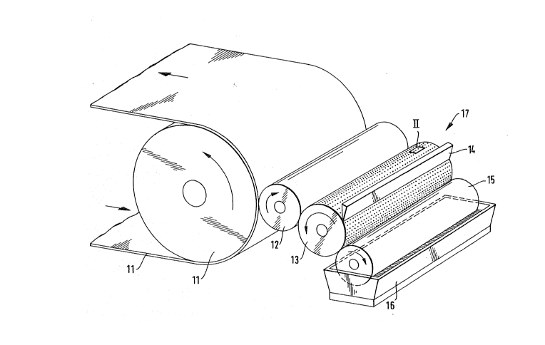
The invention is described below on the basis of the drawings:
igure 1 shows an illustration in perspective of an applicator device according to
the invention.
igure ~A, E shows considerably enlarged partial illustrations (II is a pattern roller 13 in
Figure 1) of various surface structures on a pattern roller according to the
invention.
igure 3 shows an illustration in perspective of a heatable chamber-type doctor
blade.
-
2~82723
Figure 4 shows a cross-section of a chamber-type doctor blade with ink containerand pump.
Figure 5 shows a schematic illustration of an applicator device in conjunction with
a laminating device.
Figure 6 shows a cross-section of a UV radiator with movable re~lectors.
In the applicator device shown in ~igure 1, a web material (polyethylene foil with a
thickness of 20 llm~ is passed around an impression cylinder (11) at a speed of 300
m/min. and is printed with a high-pressure roller (12). The high-pressure roller (12) is
supplied via an inking system (17), consisting of a pattern roller (13) with a doctor blade
(14) as well as an in~cing roller (15) with an ink trough (16). The pattern roller (13) has a
cell depth (t) of 6 + 1 ~m (see Fig. 2). The pattern roller (13) has the geometry illustrated
in Figure 2A with a pattern width of 180 L/cm, which corresponds to 32,400 cells/cm2,
and a C/W ratio of approximately 2:1. A solvent-free UV-curable acrylate ink (consisting
entirely of solids) with a pigment content of 20 wt.% is used. This ink has a viscosity of
0.1 Pa s at a temperature of 40 C. The high-pressure roller (12) is a common letterpress
printing block. Printing is carried out with an application thickness of 1.5 ~lrn, with
practically no different existing between the thickness of the wet and dry film. Directly
after the ink is applied to the web material (10) by means of the high-pressure roller (12),
the ink is cured by two UV radiators attached to the outer circumference of the
impression cylinder (11) (see Figure 6 for a detailed description).
Figure 2 shows the details of the surface quality of the pattern roller (13); Figures 2A,
2B, 2C and 2D illustrate the cell geometries in the order given in the form of domes,
truncated pyramids, full pyramids and cylinders, with the cell-cell wall ratio ranging from
approximately 2:1 (Figure 2A) to approximately 3:1 (Figure 2D). Figure 2E shows a
variant of Figure 2B (viewed from above) with wall indentations. With a depth (t) of the
cells (N) amounting to 10 llm, the wall regions (S) contain indentations ~P) arnounting to
5 !lm; as a result, the cells (N) are interconnected by the indentations (P), while a
sufficient amount of wall area (S) is still provided for supporting the doctor blade. In the
embodiment shown in Figure 2E, improved coveragej and thus better shading, can be
achieved for full-area printing, thereby increasing print quality.
~ ,.
2~82723
g
Figure 3 shows an illustration in perspective of a heatable chamber-type doctor blade
(52) which is closed off on both ends by elastic sealing profiles (32), (32'). By means of
additional sealing profiles (32"), (3~"') installed inside the chamber-type doctor blade
(52), the latter is divided into three separate chambers (35), (35'), ~35"), each ot` which
has a separate ink feed line (56), (56'), (56") and a separate ink level control (53), (53'),
(53"). By dividin~ the chamber-type doctor blade, it is possible to supply the separate
chambers with different inks, thereby allowing printing to be carried out with several
colors at the same time. By supplying dif~erent temperatures in an axial direction, using
temperature control devices that can be set individually (not shown), the viscosity of the
individual inks can be influenced, thereby making it possible to selectively change or
measure the amounts of ink applied. Doctor blade arms (36), (36') are adjusted and fixed
in place by means of steel spring~s (not shown). The side-mounted and internal sealing
profiles are made of non-swelling rubber. The chamber-type doctor bLIde can be easily
cleaned by removing the side mounted sealing profiles (32), (32') or moving the center
sealin~ profiles (32"), (32"').
Figure 4 shown as cross section of the chamber-type doctor blade (52) illustrated in
Figure 3; it is supplied via an ink container (58) which is connected to the doctor blade
(52) via a two-way pump (57) and a single ink line (56). The ink line (56) empties into
the chamber-type doctor blade (52) at the lowest point in the ink contents, so that fresh
ink is always supplied from below. The ink container (S~) is supplied via a feeder line
(59). An agitator (60) maintains the homogeneity of the ink (65). The chamber-type
doctor blade (52) has venting devices (66) in order to prevent bubbles from ~orming in
the ink contents (65'). Both the ink container (S~) and the chamber-type doctor blade (52)
can be heated by means of temperature control devices (69) and (67), respectively, with
the ~emperature being maintained at a constant level by means of control devices (7~) and
(6~), respectively.
Figure S shows a schematic diagram of an applicator device according to the invention in
conjunction with a laminating device. A web material (10) (polyethylene, 20 ~m) is
removed from a roll (21) and supplied to an impression cylinder (11) via a reversing
roller (22). A UV-curable laminating adhesive is applied to the web material ~10) with a
high-pressure roller (12). The high-pressure roller (12) is supplied with laminating
adhesive by means of a pattern rol-ler (13) with a heatable chamber-type doctor blade
(52). Another web material (20) (polyamide, 60 ~Im) is then placed on top of the web
.. . . . .
' ' '~ ;,
:, :
2~2 723
- 10-
material coated with the reactive laminating adhesive (10); this second web material (2())
is removed from a roll (23) and placed on the adhesive-coated web material (10) by
means of a laminating roller (24). The laminated compound material is then placed on a
roll (26~ after passing over a reversing roller (25). UV radiators (18), (18') for curing the
reactive laminating adhesive are attached to the outer circumference of the impression
cylinder (11). Bet`ore the second web of material (20) is applied, the reactive adhesive is
pre-cured by the UV radiator (1~), with care being taken to ensure that an adequate
degree of tackiness is available for applying the second web material (20), thereby
ensuring a strong lamination bond. After the second web material (20) is applied, the
adhesive is re-cured with the UV radiator (18'). The web speed of the impression roller
(11) is 150 m/min. A solvent-free, UV-curable laminating adhesive based on epoxy resin
with a viscosity of 0.6 Pa s at an operating temperature oE 60 C is used. The adhesive is
applied all over in a volume of 3 glm2, which corresponds to an application thickness of
approximately 3 ~m. A pattern roller (13) with the geometry illustrated in Figure 2E and
having a pattern width oE 170 and a C/W ratio oE 3:1 is used (the wall depressions are
calculated as wall). The entire system is maintained at an operating ternperature oE 60 C
by means of appropriate temperature control devices.
Figure 6 shows the details of this type of UV radiator. This type oE UV radiator (61) has a
UV radiation source (63) with an energy density of 150 W/cm (in an axial direction)
which is installed in a water-cooled housing (62). Movable reflectors (64), (64'), which
are also water-cooled, are installed inside the housing; these reflectors automatically
move between the radiation source (63) and the impression cylinder (11) in the event oE
malfunctions, in particular when the system comes to a standstill (see Figure 5), thereby
preventing the web material (10), or (10) and (20) from overheating (see Figure 5). In
addition, a control device is provided (not shown) which automatically adjusts the
radiation power when changes occur in the web speed of the impression cylinder (11).
.