Note: Descriptions are shown in the official language in which they were submitted.
~0 ~l!lYI;!7 : . P(~!US9!/!)3844-
` 2~S~$2~3
DEVICE FOR SEALING A PLASTIC PIPE
EXTENDING THROUGH A PARTITION
TE CHN I CAL F I ELD
This invention pertains to a device for sealing
a plastic pipe extending through an opening in a partition
in the event of a fire.
BACKGROUND OF THE INVENTION
In buildings, plastic pipes are progressively
being used in lieu of metallic pipes. Plastic pipes,
however, unlike metallic pipes, pose fire containment
problems. In a fire, the plastic pipes will melt or burn
leaving openings in the partitions (e.g. walls, ceilings,
floors) which permit expansion of the fire. Devices have
been made to combat this kind of fire expansion.
Germany Utility Model 89 07,017 published
October 5, 1989 discloses a plastic pipe sealing device
having a collar that includes a radially outwardly
-extending fastening portion at one end for attaching the
device to a wall or a ceiling. The device also has a
tubular portion extending away from the wall ol the
ceiling adapted to accommodate a lining of intumescent
-~ material. An annular portion of the collar extends
radially between the plastic pipe and the tubular portion
- retaining the lining of intumescent material-within the
collar.~;In the event of a fire, which causes the plastic
. ;pipe to collapse or burn, the intumescent material expands
to fill-the-opening through which the collapsed;or burned
plastic pipe passed. A fire-resistant barrier~-is thereby
I- s-35 ~formed which prevents an expansion of fire and ~passage of
!smoke from one room to another. The front annular portion
of the collar prevents the intumescent material from being
axially expanded beyond the collar.
.. : .
' . ' ~ '
'.
With plastic pipes of up to medium diameters
(e.g. on the order of about 30 to 100 mm), the device
disclosed in German Utility Model 89 07t017 works
satisfactorily. If the pipe diameter is relatively large
(e.g. greater than about 100 mm), however, the intumescent
material cannot sufficiently seal the pipe in a timely
manner because the intumescent material typica~ly needs a
few minutes to chemically convert and expand. Within this
time, flames, gases, and smoke ~ay pass through the
10 opening.
From the prospectus of bio ~RANDSCHUTZ system
CRASH-FOAM, it is known to enclose a pipe in a collar that
has spring-biased closing parts. When the plastic pipe
melts in a fire, the spring-biased closing parts will seal
the pipe. Such fire-protection collars are relatively
expensive to manufacture and have costly material
inventory. They require a lot of space and have a poor
appearance.
Japanese Utility Model Laid Open Application
64-57479 published April 10, 1989 illustrates a device for
sealing a plastic pipe in the event of a fire. The device
has two springs, one on each side of a wall through which
the pipe passes. The springs encircle the pipe under
tension to close the pipe when the pipe becomes soft from
heat generated in a fire.
U.S. Patent 4,559,745 to Wexler discloses a
device for "shutting-off" plastic pipes in the event of a
fire. The device includes a collar having an intumescent
material packed therein, a refractory fabric, and a
tension spring. The collar and intumescent material are
embedded in a wall or floor of a building. ~The refractory
fabric encircles the outside of the plastic -pipe inside
- and outside of the wall or floor.- The tension spring is
located outside of the wall and .is placed
circumferentially around the refractory fabric and plastic
-- -pipe.
--- - The device of U.S.~Patent 4,559,745 has at least
two deficiencies.~ Firstly, the tension spring is located
in a position that hinders activation of the intumescent
" , , . - ~ , ' ' ' ~'
', ~ ~ .. '. : ' '
.~_
- _3_
;'_~vr.~vr~_
material. When the tension spring constricts about the
pipe, hot gasses are restricted from passing through th~
pipe to the intumescent material. The intumescent
material therefore would not be activated as quickly.
Secondly, the spring is not protected from being damaged
by heat from a fire. Heat from a-fire can damage the
tensile properties of the spring, injuring the spring's
ability to constrict and seal the plastic pipe.
W0 87/00761 published February 12, 1987
discloses a composite fire stop device having two tension
springs, each located on opposite sides of an opening of
an annulus of intumescent material. A sheath of
refractory fabric is located between the outer surface of
the pipe and the intumescent material. Fingers of the
refractory fabric are placed around the tension springs to
hold the springs to a support sleeve. The device
disclosed in this patent possesses the same problems
discussed above for U.S. Patent 4,559,745: (i) the springs
and intumescent material are not positioned in the device
in such a manner that, upon softening of the plastic pipe
and closure of the spring(s), heat from the fire can still
pass unrestricted through the pipe from the heat source to
the intumescent material; (ii) and the spring is not
fully protected from heat generated in a fire because
' 25 there are open spaces between the fingers of refractory
fabric. - ' ' '
,
SUMMARY ~F THE INVENT$0N :
' - The above-noted problems in the art are overcome
by the new and improved plastic pipe sealing device of
- : this invention. This~new plastic pipe sealing device has
' ~ a collar 'with an opening for?`-a ~plastic-pipe to pass
therethrough.: The ~-collar ~contains a first and second
: "35; means for sealing thè~-plastic pipe~.: The`;~first sealing
.? ~ ;`' means seals the plastic pipe ~when heat ~from' the fire
-causes that-pipe to become soft'.;~:~"This`occurs~!before the
second sealing means acts to ~eal the plastic pipe. The
second sealing means acts to seal the plastic pipe after
- being exposed to a sufficient amount of heat. The first
and second sealing means are arranged in the collar so
that when the device is mounted in or on a partition the
first sealing means is located closer to the center of the
partition than at least a portion of the second sealing
means. Upon closure of the plastic pipe by the first
sealing means, the plastic pipe still has a portion of the
pipe open in communication with the fire or heat source.
This open portion permits heat to more readily reach at
least a portion of the second sealing means to induce its
closure of the opening.
A preferred first sealing means of the invention
includes a radially compressive means such as a helical
spring. The radially compressive means can be protected
from heat damage by being completely enclosed in a means
for protecting the radially compressive means. Such a
protecting means can include a layer of a fire-resistan~,
deformable, heat-insulating material. This kind of
material protects the tensile properties of the radially
compressive means from damage caused by heat, and it also
assists in sealing the plastic pipe.
Thus an object of the invention is to provide a
device for sealing a plastic pipe in the event of a fire,
which can seal the plastic pipe;without restricting the
flow of heat to a heat-activatable sealing means such as
an intumefscent material.
Another object of the present invention is to
provide a device for sealing a plastic pipe which
.. . ....
insulates a radially compressive means such as a spring
:~-?30~ ifrom heat generated by-a -fire so as to preserve the
-~ spring's function.
fj ~ ~ . The above ~objects and other novel features of
.i~ ! the~invention are more fully described and illustrated in
the~ following detailed description and accompanying
jt;`,' 35 drawings, where like i reference rnumerals are used to
defsignate similar parts.- It- is to be expressly
understood, however, that the description and drawings are
.'.` `, . `.. ~ ~. . ' . ;, . : . ,
n- ~7
' ` ' ' ' ' ' ' '--' ~ `._ ~ i V~7 i iVJ~
.:
for the purposes of illustrating the invention and are not
to be read in a manner that would unduly limit the scope
of this invention.
As used herein, the term "plastic pipe" means
any conduit composed of a substance(s) that permits the
conduit to soften or melt after beiny exposed to heat from
a fire.
BRIEF DESCRIPTION OF THE DRAWINGS
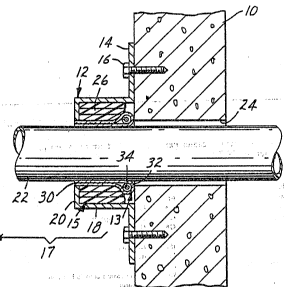
FIG. 1 is a perspective view of a device for
sealing a plastic pipe in the event of a fire in
accordance with the present invention.
FIG. 2 is a partial cross-sectional view taken
along lines 2-2 of FIG. 1 illustrating a device for
sealing a plastic pipe in the event of a fire in
accordance with the present invention.
FIG. 3 is a perspective view of a helical
spring for use in the devices depicted in FIGs. 1, 2, 4,
and 5.
FIG. 4 is a partial cross-sectional view of a
further embodiment of the present invention illustrating a
radially compressive means inside a-collar adjacent to a
partition. ' -'
25FIG. 5 i5 a cross-sectional view of a further
embodiment of the present invention illustrating a
radially compressive means located centrally in a coilar.
DETAILED DESCRIPTION OF PREFERRED EMBODIMENTS
- ' In-describing the preferred embodiments of the
-- present invention, specific terminology will'be used for
. the sake of-clarity.'' 'The invention, however, is not
intended to be~limited to the''specific terms so selected,
', ;!''35 -and '`it is 'to'be understood that '~eàch' term so sçlected
includes -all -the tçchnical --'equiv`alents ~-that operate
similarly.
. . . ~ . . .
.. . . . ..
wn 01!l0l~? ~ n~/~lSn~ 04~
Looking first to FIGs. 1 and 2, a collar 12 is
illustrated that contains a first and second means 13 and
15, respectively, for sealing a plastic pipe 22. First
pipe sealing means 13 can include a radially compressive
means such as the spring identified by the numeral 34.
Spring 34 is shown encircling plastic pipe 22 under
tension adjacent collar 12. In a fire, tension from
spring 34 causes a progressive strangling of plastic pipe
22 as the pipe softens and becomes ductile from heat
generated by the fire. Tension spring 34 is shown to be
contained within an enclosure 30 that will contract in
conjunction with spring 34 to seal pipe 22 in the event of
a fire. ~nclosure 30 is comprised of a fire-resistant,
deformable, heat-insulating sheet material that insulates
spring 34 from heat so that it can maintain its function
for a longer duration while being exposed to high
temperatures generated in a fire. ~his kind of protection
is maintained at least until the commencement of the
effect of the second sealing means 15. Second sealing
means 15 can include a heat-activatable intumescent
material identified by numeral 26.
Tension spring 34 can be attached to an inner
side of enclosure 30 by suitable fastening means, for
example, by sewing. In the embodiment of FIGs. 1 and 2, a
layer of the fire-resistant, deformable, heat-insulating
material is folded at 32 with the spring bein~ located in
the looped end between superimposed layers. Upon
contraction of spring 34, enclosure 30 contemporaneously
-closes therewith to assist in sealing the plastic pipe to
prevent passage of flames, smoke, gases, and the like.
; Preferably, two~layers of folded material 30 extend into
^r: ~?i collar 12 -radially inward of ^intumescent material 26.
Enclosure 30 can be made of a flat blank of sheet material
, . ~ . . . .. .
' ,,_ !' j, that is wrapped around plastic pipe 22. The flat blank of
... . . .. . .. ..
sheet 3 material jhas a ;first portion that is located
~J ~ radially~inward~of an opening of an annulus of intumescent
material 26, a second portion that is folded at 32 about
spring 34, and a third portion that is located radially
inward of an opening of an annulus of intumescent material
.
.
.
.
W3,~,~, A ~ / VS Y i/~3~
_ 7 _
, . . . , . , , _ , . . . . . .. . ................ . .
, " ~, ~
26. Alternatively, enclosure 30 can be a double-layered
hose. In this event, enclosure 30 will be slid over
plastic pipe 22 prior to its assembly. It is preferred
that the layer of fire-resistant, deformable, heating
insulating material be wrapped around the plastic pipe for
a distance of at least one half the diameter of the
plastic pipe. `
Enclosure 30 preferably consists essentially of
a deformable textile fabric that is fire-resistant and
heat-insulating, preferably made from .high .temperature
resistant inorganic filaments such as ceramic filaments,
for example, alumina-silica-boria fibers. Two examples of
alumina-silica-boria fibers are indicated as follows:
62% Al2 03
1524% SiO2
14% ~2 3
or
70~ Al2 03
28~ SiO2
202~ ~2 3
Fabrics made from these filaments are available from 3M
under the trademarks NEX~EL 312 and NEXTEL 440.
- The ~ fabric of - enclosure : 30 preferably i5
relatively smooth so that no parts or filaments of the
enclosure extend::-between the turns of spring 34, which
could prevent the spring from being completely contracted.
The fabric preferably has :a relatively small mesh to
. restrict. flamesi gases,. smoke, and contaminates from
passing therethrough. .~
: In.the~event of-a fire,~.a typical plastic pipe
will~soften:when it-reaches a temperature of-about 80 to
-140:-.~ Upon-a3softening or melting of pipe 22, spring 34
i;: under .tension ~contracts and-takes ~along ^the~associated
3s~.~;part:i~of:~enclosure~30,~ forming .a~.barrier:--that prevents
penetration of:flames,~smoke,.;gases, and other.corrosive,
aggressi~ve or tox~ic.gases. i~Enclosure~30-protects spring
- -34~so~ that ~it ~will- not. be rendered -useless by the
influence`of heat. The above-mentioned examples of fabric
~: :
.
, '
.
r~, ~ i'u~Y; i~
.
-- - -- 8 --
- for the enclosure may resist temperatures of up to 1200 c
to effectively protect the spring for at least about 15 to
20 minutes. The device works with smoldering fires and
high intensive fires, for example, fires with oil, gas,
solvents, etc. Enclosure 30 together with spring 34
thereby forms a temporary sealing of the opening duc~
until the intumescent material 26 has had sufficient time
to react and to expand.
, A nonwoven material made of inorganic fibers
- lO could .also be used as -an enclosure 30. The nonwoven
material should be selected to provide properties similar
to the above-mentioned fabric. ..
Turning to FIG. 3, a spring is illustrated that
can be used in the present invention. The spring
preferably is helical and preferably is made of stainless
steel. The spring can be designed and dimensioned such
that a ductile plastic pipe is compressed to a fraction of
its diameter. As shown in the figure, spring 34 has a
hook 36 at at least one end to retain the spring in an
annular shape. Spring 34 is wound around plastic pipe 22
under tension. As illustrated, two layers of enclosure 30
may be wrapped about plastic pipe 22 radially inward of
intumescent material 26 extending through opening 24 in
.. : partition 30. Enclosure 30 may extend beyond collar 12 to
25 .a greater or lesser extent, but preferably extends at
. least partially within an opening of an annulus of the
.. -intumescent material 26.
-. : As shown in FIGs. 1, 2, and 4, collar 12 can
:: .- have.a means for fastening the device to a partition such
as a wall. Such a means can be a radially fastening
;~.. ; ~portion or~flange.14 .which can be attached to wall lO by
" using means such as screwbolts 16. Collar 12 also
comprises ~a tubular portion .18 extending from the inner
,end.~of radial flange;14 away from wall 10. -An annular
radially..inwardly facing portion 20 is shown at the~end of
tubular portion- 18, portion .20 extending proximately
adjacent.to the outer side of plastic-pipe 22. Plastic
3t`~ . ~ pipe ~22 extends through tubular portion 18 of collar 12
. and an opening 24 of wall 10. Collar 12 can resemble, for
.- : :,
- .:
'
,: ' , " ' ~ . . , , : .:' ' .: .
`' ' ' ' ' ' ~ ~ ' - r S r,' 'J.'~-7 i /VJOW
.. : . . , . ~
s~
example, the collar of the German Utility Model
Application 89 01 017 in regard to structure. Collar 12
can be formed, for example, from two heat-resistant
metallic semi-cups.
A plurality of layers of an intumescent material
26 can be positioned in tubular portion 18. The
intumescent material greatly expands in volume upon
exposure to heat in the event of a fire. Intumescent fire
' protection material is commercially available as a
' '' 10 deformable preproduct in the form of tapes, plates, strips
' or the like. 'In most cases, a resilient plastic material
'is used which expels steam during the intumescing process.
A material distributed by 3M under the designation FS 195
AA is suitable. Intumescent materials are disclosed in
' 15 U.S. Patents 4,234,639 and 4,273,879.
: Turning to FIG. 4, a further preferred
' embodiment of the invention is illustrated. In this
- embodiment,' the first and second means-13 and 15 for
sealing plastic pipe 22 are contained in collar 12. First
means 13 (such as a spring 34 and a layer of fire-
resistant,' deformable, heat-insulating material) is
' arranged in collar 12 so that when the device is mounted
- ' to partition lO,'`the first sealing means 13 is located
;-c}oser t'o~''the' center``of partition 10 than the second
sealing means 15. Upon closure of the first sealing means
13,~ plastic pipe~-22 will still have a portion 17 open
a- p'roviding communication between the heat source and the
i ' - ^~!'sècond`sealing 'means 15 (such as an intumescent material
''26~ Spring~34 is`located-in a portion of collar 12 that
''/30'~ ;s'~adj~acent~'to'':pa'rtition '-'-10 when the;device is mounted.
9-n~'Thè:~i''ntumescent~material 26 is located~further away from
partition 10, closer-to annular-end face portion 20. The
plastic pipe 22 therefore can be sealed by the spring 34
; without restricting the flow of heat from a fire to
intu-escent~màterlal 26, thereby providing for an.earlier
o10sure of~ the plastic pipe 22 by the intumescent
material.
: - . - ~ ~ ~ , . . - - - . .
-, : .: , - , - : - .
. - .... . . . . . .
.~ . : '::. ' '' ' ' . ' . : '
: . ,,:, : . . , ' .
- .~;,~'33?iJ~3 ~
--,. .,~J
., , , ~ .
Turning to FIG. 5, a further preferred
embodiment of the invention is shown. In this embodiment,
spring 34 is located centrally in collar 12'. Collar 12'
has a tubular portion 18' and annular radially inwardly
facing portions 20l. Intumescent material is located in
collar 12' on opposite sides of spring 34 as indicated by
numerals 25 and 27. This embodiment is particularly
suitable for placement within a partition 10. As with the
embodiment shown in FIG. 4, this embodiment also allows
plastic pipe 22 to be sealed by spring 34 without
obstructing heat flow to the intumescent material 26.
This embodiment of the device possesses this advantage for
fires originating on both sides of a partition 10.
In the embodiment of FIG. 5, the fire-resistant,
deformable, heat-insulating material can protect spring 34
by, for example, placing one layer 29 of such material
radially inward of first and second portions of
intumescent material 25 and 27, respectively, and radially
inward of spring 34. A second layer 31 of fire~resistant,
deformable, heat-insulating material can be placed
radially inward of first and second portions of
intumescent material 25 and 27 and radially outward of
,. spring 34:to completely surround,spring 34. The layers
. : can be joined at the spring~34, for example, by sewing the
:'~ 25 ,layers together. . . ..
, , Various modifications ,and alterations of the
invention will be~apparent to,those skilled in the art.
Accordingly, the present invention is. to be defined by the
: .limitations contained ,in,.,the clai,ms,,and ,.equivalents
,-,,,- 30 :thereof. It is, to -be understood ~that.this invention may
'- 4 . be.~,suitably practiced in,the,absence.~.of ,any-element not
,.specifically disclosed,..herein. - ~.- . ---........
. .', . . :. ~ - :.,.-
: . . .
. . - , : . . ' :
-: . : ': . .. '
: : ' .:
,," ': ' . , :
.
,